-
Software Works: GUI and Video Stream
06/12/2016 at 14:23 • 0 commentsThe various developments that have gone into developing the software and backend will be explained in this log. This log also explains about the problems we’ve faced in trying to get a live feed from the Picamera onto the webpage.
We are not having any problem with direct feed given by picamera library; it runs fine, but it does not run in a browser. (Still working on that problem).
The other option to overlay the preview on top of the browser did not work. It showed multiple conflicts with the custom version of Raspbian – Wheezy that we are using.
The Builds 2.2 to 2.5 of OWL (refer Github repository) have worked on work around making the simple GUI work and also the display of the feed.
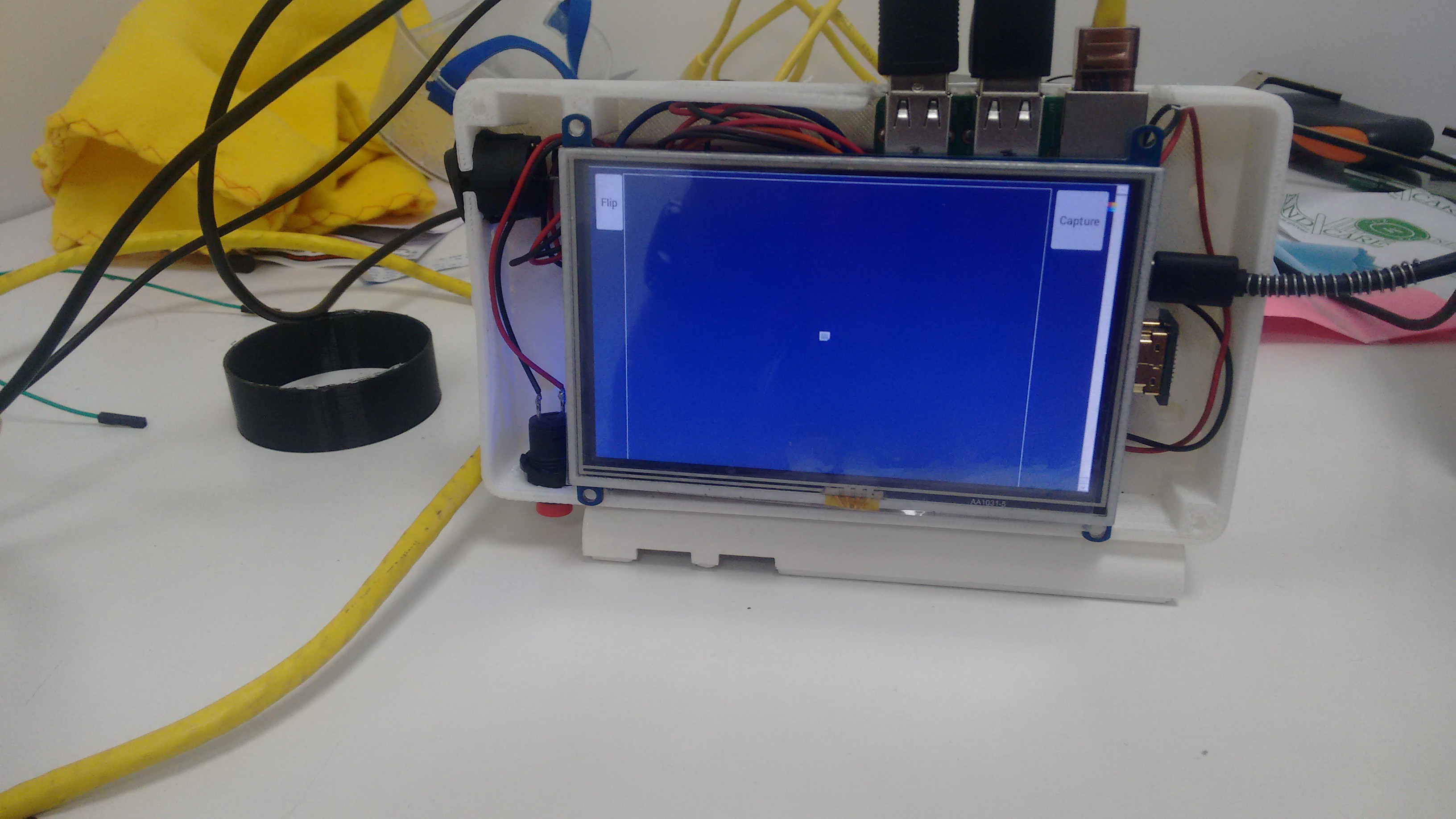
The simple GUI with a flip and a capture button has been done as shown:Flip was to be used when the image got inverted due to lens optics.
The centre portion was used to display all required live streams.![]()
The layout and style was changed later. This was only the test version.
The following problems came while working with the feed.
- Lag
- Blur
- Memory Limiting
A feed of Picamera, is formatted in h264 video format. So using html5 tags for the videos was of no use (ref. <video> ).
The first method we used to solve the problem was to to use openCV. The process was as follows:
- The stream was sent to Fundus_Cam.py frame by frame and each frame was converted into jpeg which was then sent to the webpage where it was displayed using the <img> tag. The feed was shown but the lag in the stream was around 2-3 seconds. Changing input and frame rate and resolution did not have much effect on the latency.
- VLC streaming: The second method adopted wast to stream a raspivid HTTP stream directly to the webpage which has VLC webPlugin installed. The lag was even more although the video was fluid. Running the same thing directly on the VLC player itself did not solve the problem.
-Next we change the HTTP stream to RTSP steam. This did not solve the problem either. (Learn more here: http://www.remlab.net/op/vod.shtml )
This made us realise that the problem associated with the stream is not connected to either browser or the application that we are using. On carefully checking all the associated logs we found that the stream sent via HTTP itself was laggy. If a frame was 'late', the server waited for it to be displayed. This caused the delay. Similar delay was not seen with USB cam though. Or the webcam.
So, to better the solution we checked for protocols used in live conversation and video conferencing.
We found out that the problem was in the transport layer. Till now all our attempts used TCP to transfer and display the stream. For, a live stream UDP is the better transport method since only the 'live' packets are focused on and lagging ones are dropped. This is the next thing we are going to try for the stream.
In other things, a JQuery keyboard based on https://mottie.github.io/Keyboard/ was implemented. Now the text box/patient details can be entered directly using the touchscreen input.
One other major change that is implemented is the usage of iceweasle (Firefox) instead of Chromium due to no support of it for Rasbian. There were a number of problems coming up due to absence of official support of Chromium. The kisosk mode is supported in Iceweasle too and anything associated with Chromium can be seen here.
Also, x-vlc-plugin was not officially supported in Chrome since chromium 42. This made us switch to Iceweasle (Firefox).The next part for the Webpage - form development is to store patient data.
-
The Assembly
06/12/2016 at 10:12 • 0 commentsWhile every aspect of the project was being thought through, the mechanical team was simultaneously designing an assembly for the equipment.
This involves everything starting right from designing holders for every individual component like the lenses used, the mirrors, camera, etc. to designing a casing to house all the components together so they’re intact, safe and also easy to be held.
To make each of the parts of the assembly, we majorly used 3D printing and laser cutting.
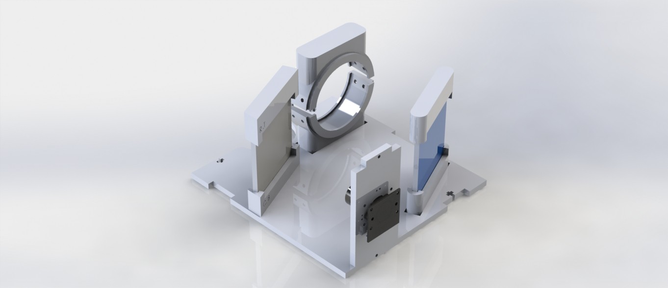
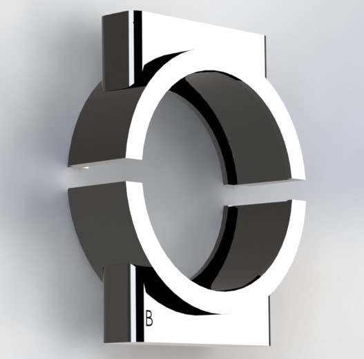
The lens, mirror, camera and light source holders are designed such that they hold the mirrors, the lens, the camera and the light sources in place, such that they stay at an optimal distance to get the most desirable result light path. These parts were 3D printed and they easily fit into a laser cut outer casing that keeps the optic system undisturbed.
The lens mirror holders look like this:
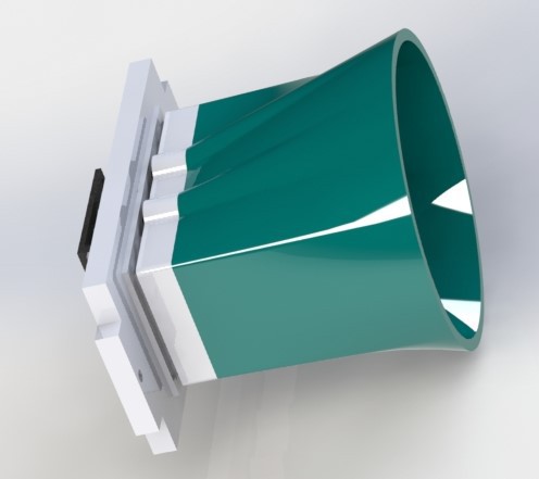
And the camera and Light source holder, with a new addition of mount that helps remove glare and reflections:
And this is a recent addition we made to the camera holder. A mount that proved to reduce the glare and reflections in the image captured by the camera, as expected.
This is a partial assembly showing exactly how the optic set up isdone with the laser cut parts.
Every component was carefully designed so that it easily fits and serves its purpose while it occupies minimum space because the lighter the device, the easier it is to handle.Take this for example. It is a support we designed for the batteries, primarily.
The device being self powered, has a strong battery back up. To hold the batteries in place, the following part was made, which easily screws on to the outer most case. this holds the batteries intact in their place, bu also serves as a base to the power bank PCB. And its location is such that its microUSB port very much accessible. So, all in all, the battery supports were designed such that they serve more than just one purpose, thereby eliminating the need for the more independant components. This helps assembling the device less time taking, compact and as optimised spacially as it can possible get!!
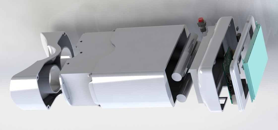
And now, this is an exploded view of the whole assemble of his project, we like to call OWL. This image shows exhaustively, the components of OWL.
But the renders of almost anything can look cool! So now, enough with the renders. Here are some images of actually assembling Owl.The most important elements of Owl in this housing. The optic setup. The design didn't take as much time as its printing did! It definitely turned out better than expected. An easy fit, the optic setup gracefully snaps into the 3D printed housing. This is one of the three primary outer most housing which are later combined into one simple and elegant looking case.
![]()
The assembly is designed such that every independently functioning element of the device can be detached separately without disturbing the remaining.
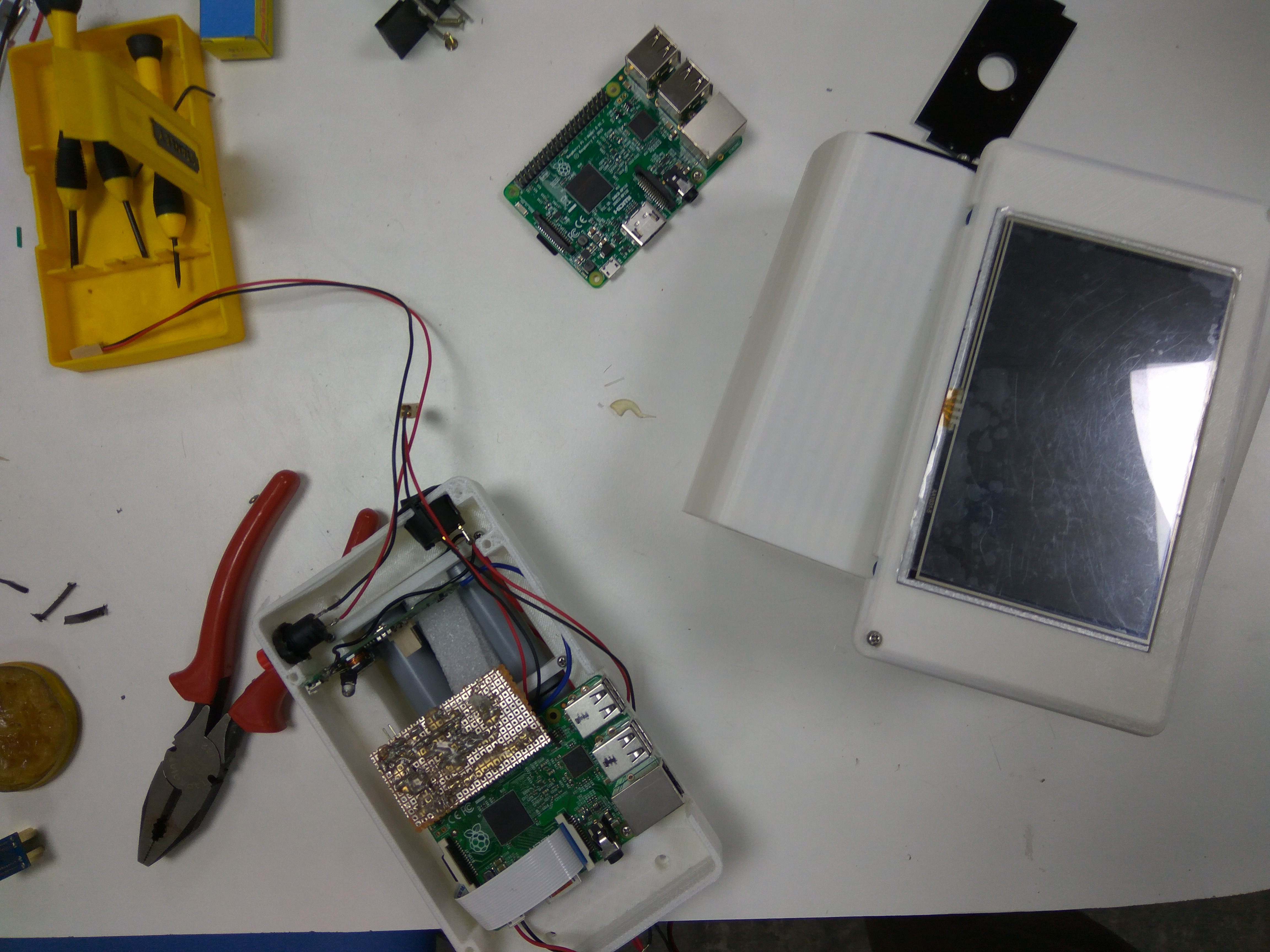
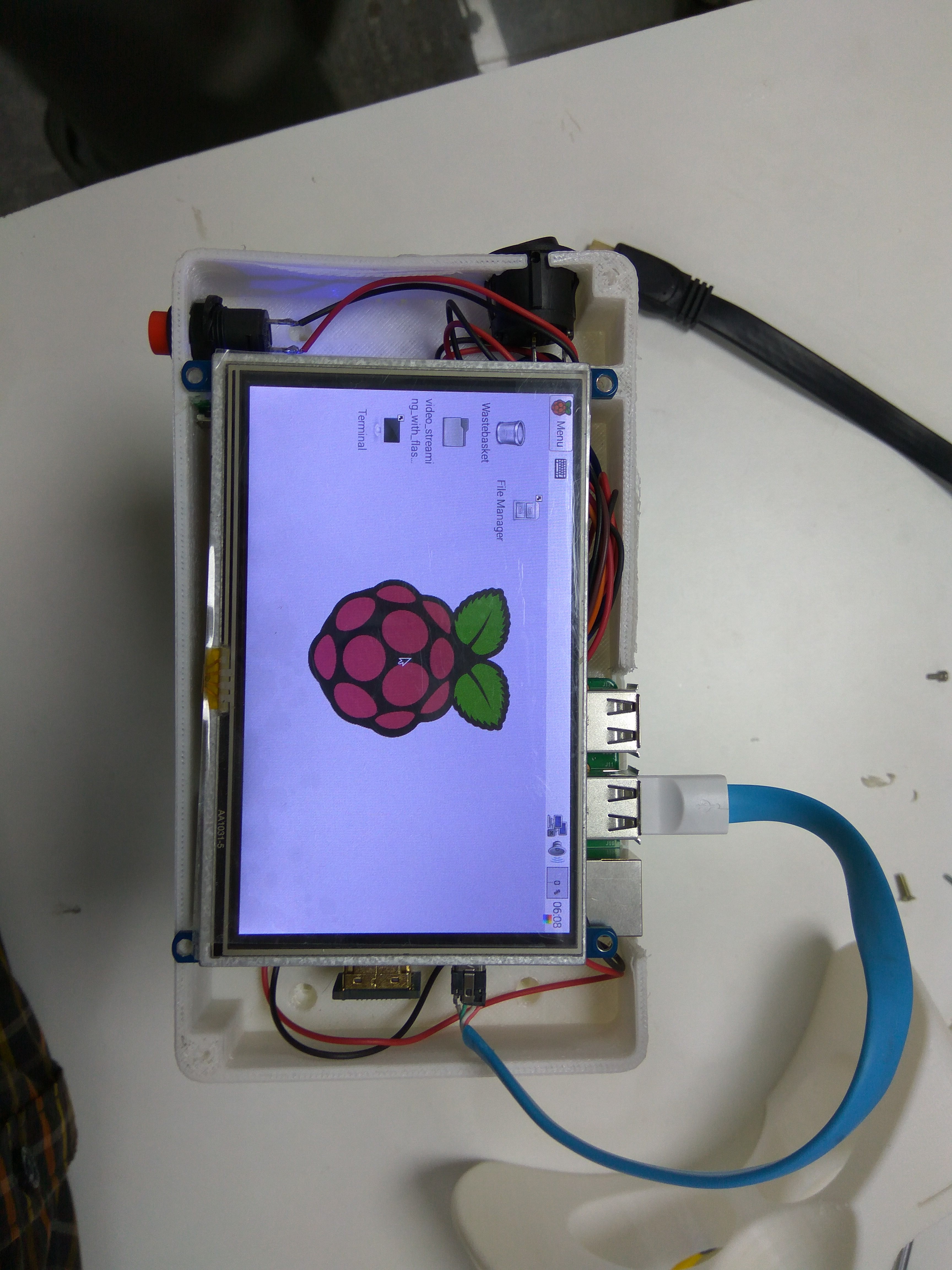
This here, is the assembling of the Raspberry Pi with the LCD screen, both in a separate case that snaps into the optics casing.
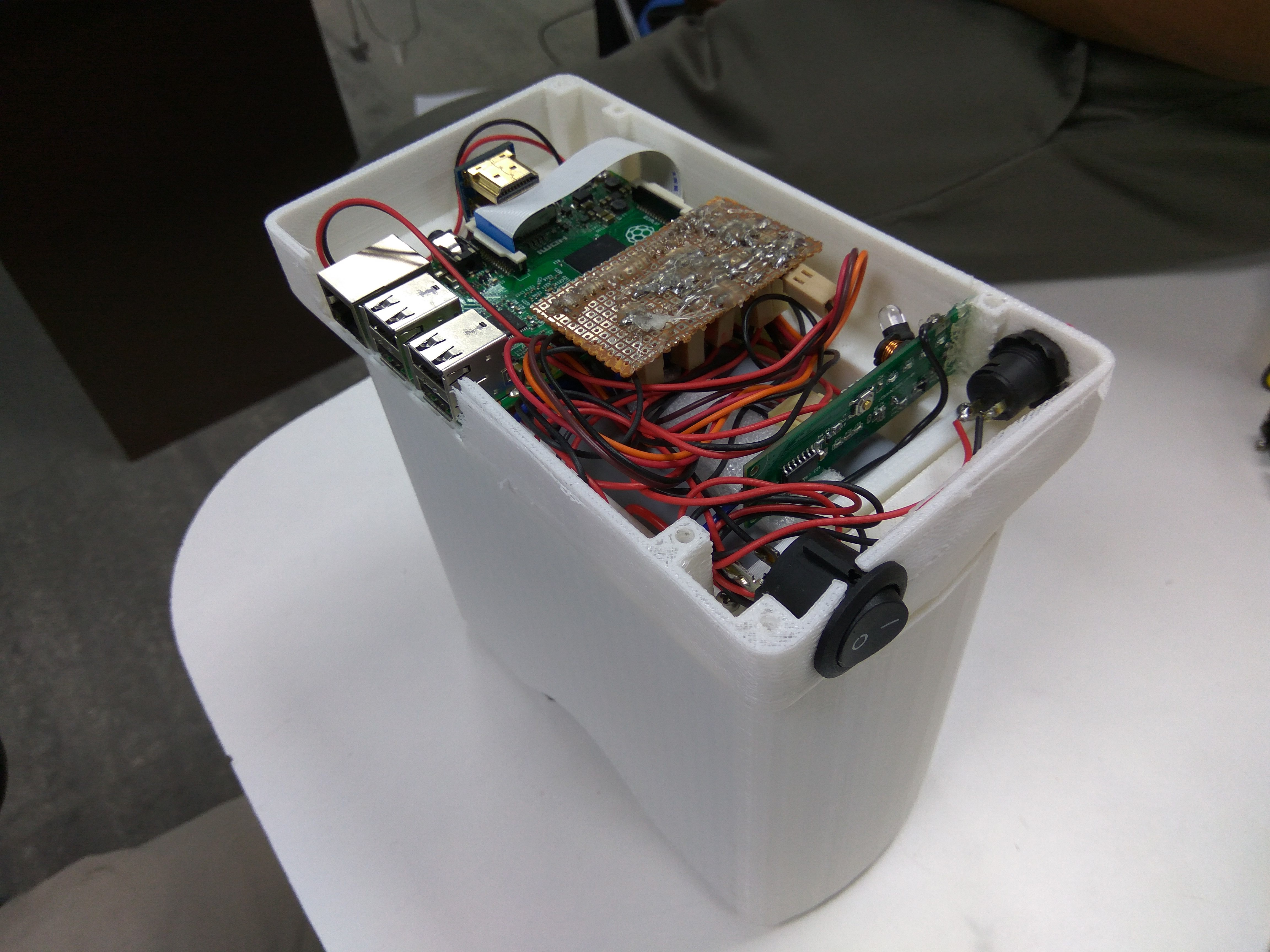
This part houses an rPI, five batteries which give a overwhelming power back-up, a couple PCBs and two switches. The image below shows how it fits and assembles with the optics case.![]()
![]()
There are two switches externally accessible. The rocker switch is the master power switch. The push button switch in the first quadrant is an external access to click images of the retina. On this, is another cover that holds the 5 inch LCD screen, connected to the rPI via a HDMI connector.
![]()
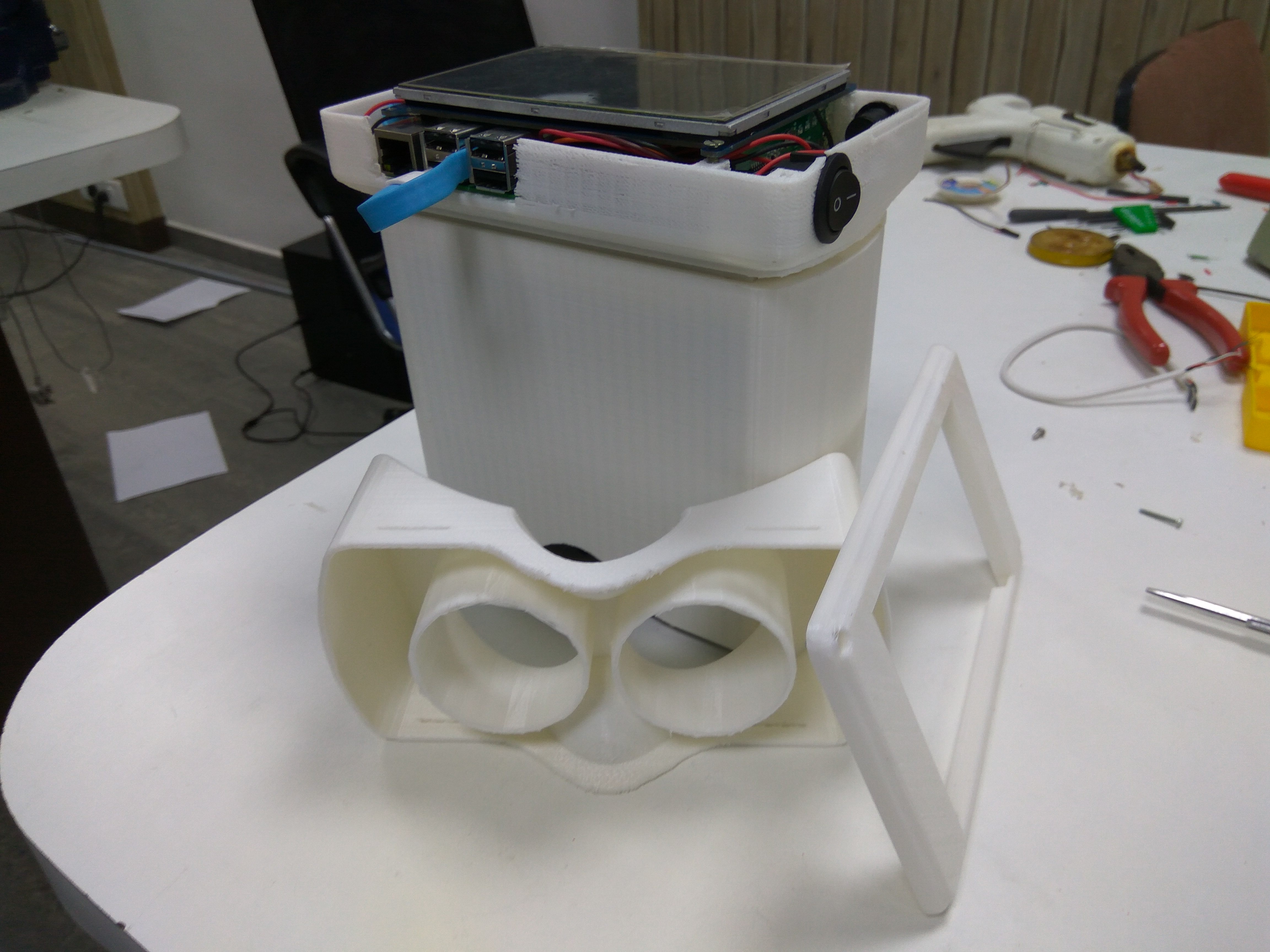
These two sub parts of the assembly are now fit in with a third and final sub part, the eye gear. The eye gear is also 3D printed, but the designing of this part was the most challenging. While keeping in mind the spacial constraints as well as the fact that the optimal distance between the eye and the lens has to be maintained, the eye gear had to be made such as it has a comfortable fit on the eyes. In fact, because the device is flipped horizontally for capturing the second retina, i.e, of the right eye, the eye gear has to be symmetrical about the X axis. Still, the output seems to be reasonably good.
The image below shows the three sub parts of the casing before assembly.
![]() The three parts are easy to snap-fit, but also have screw fixes just to make it safer.
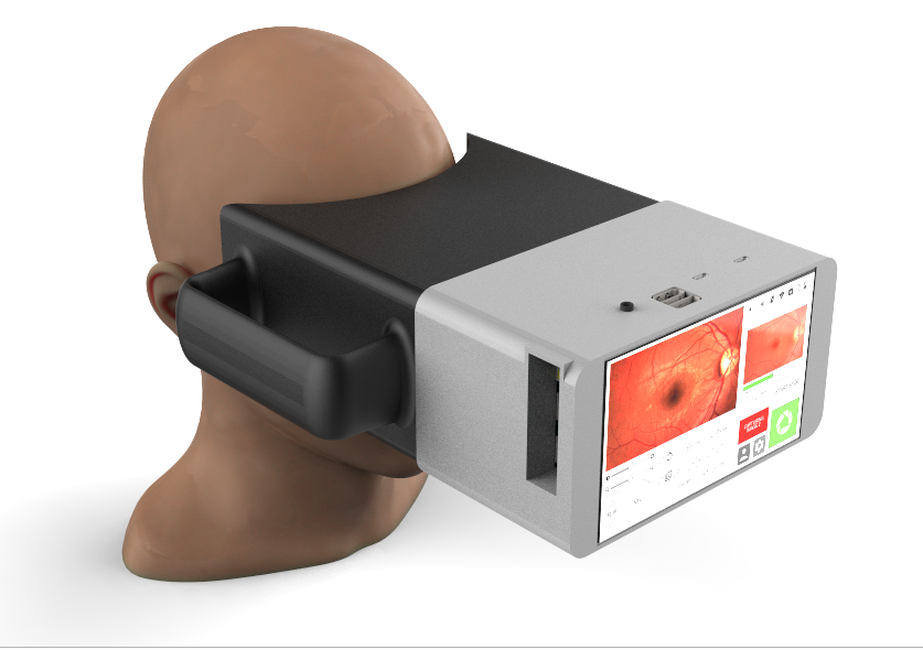
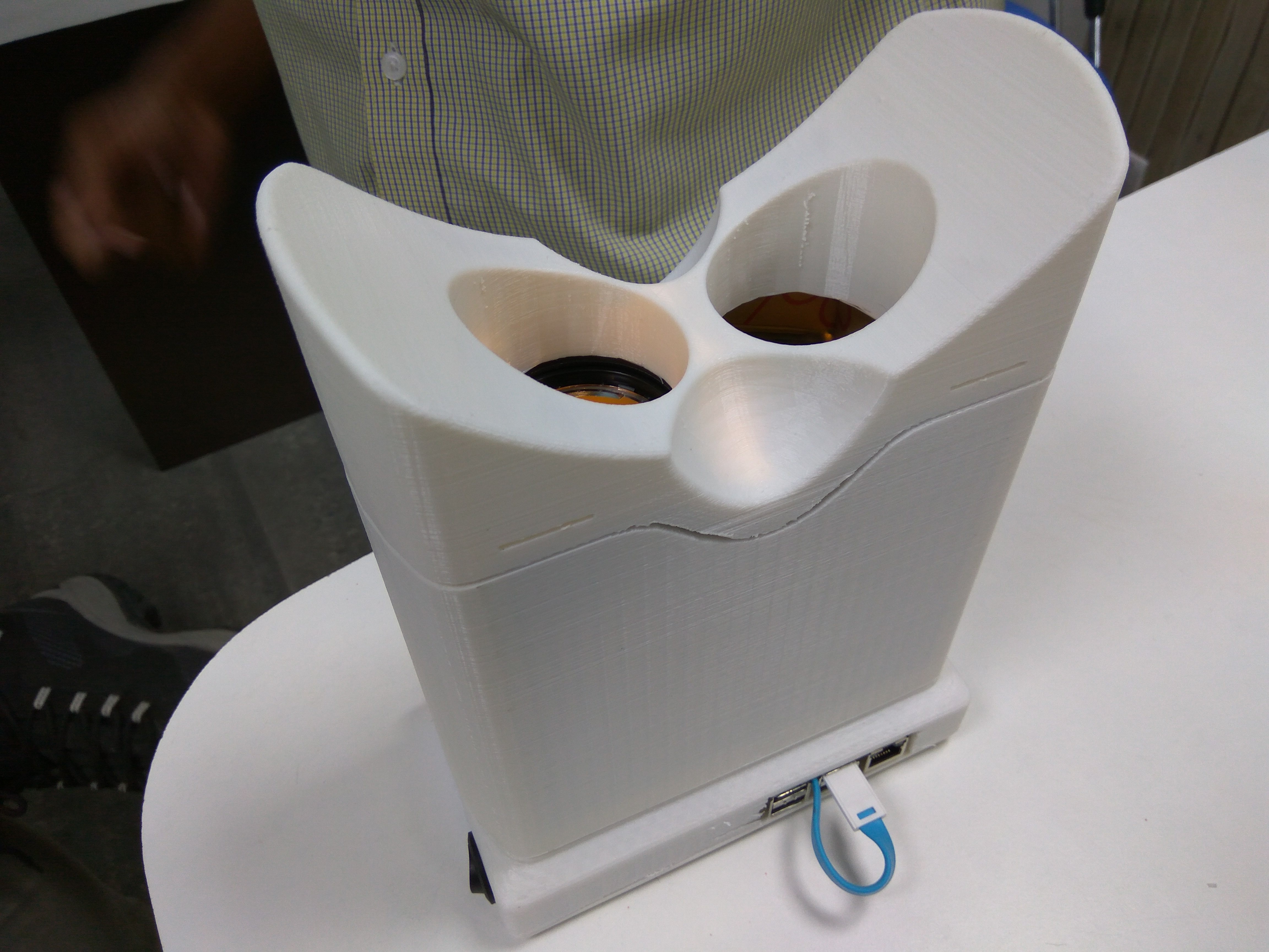
The three parts are easy to snap-fit, but also have screw fixes just to make it safer.And this below, is an image of the final assembly.
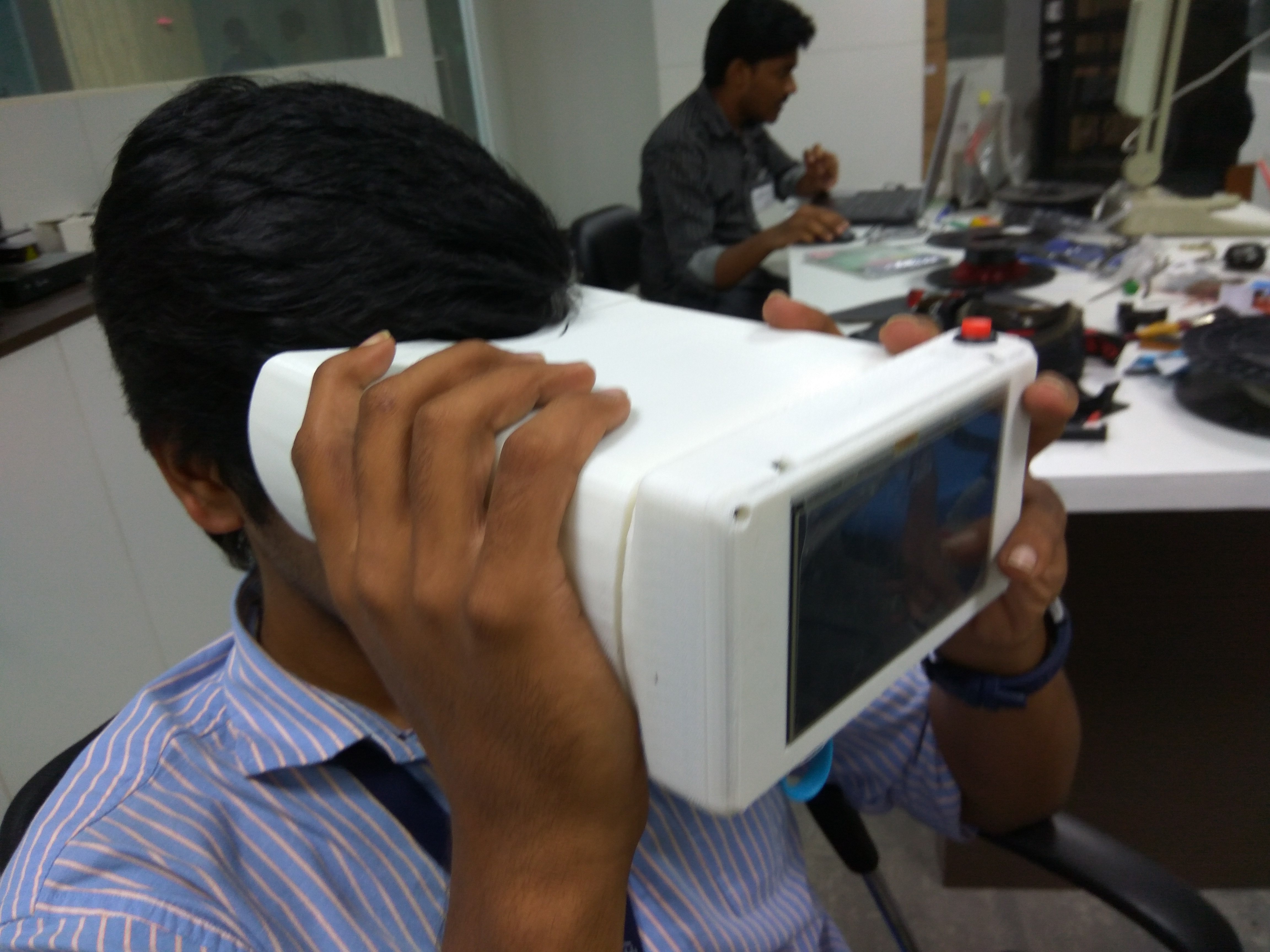
And it fits well on the average head too.![]()
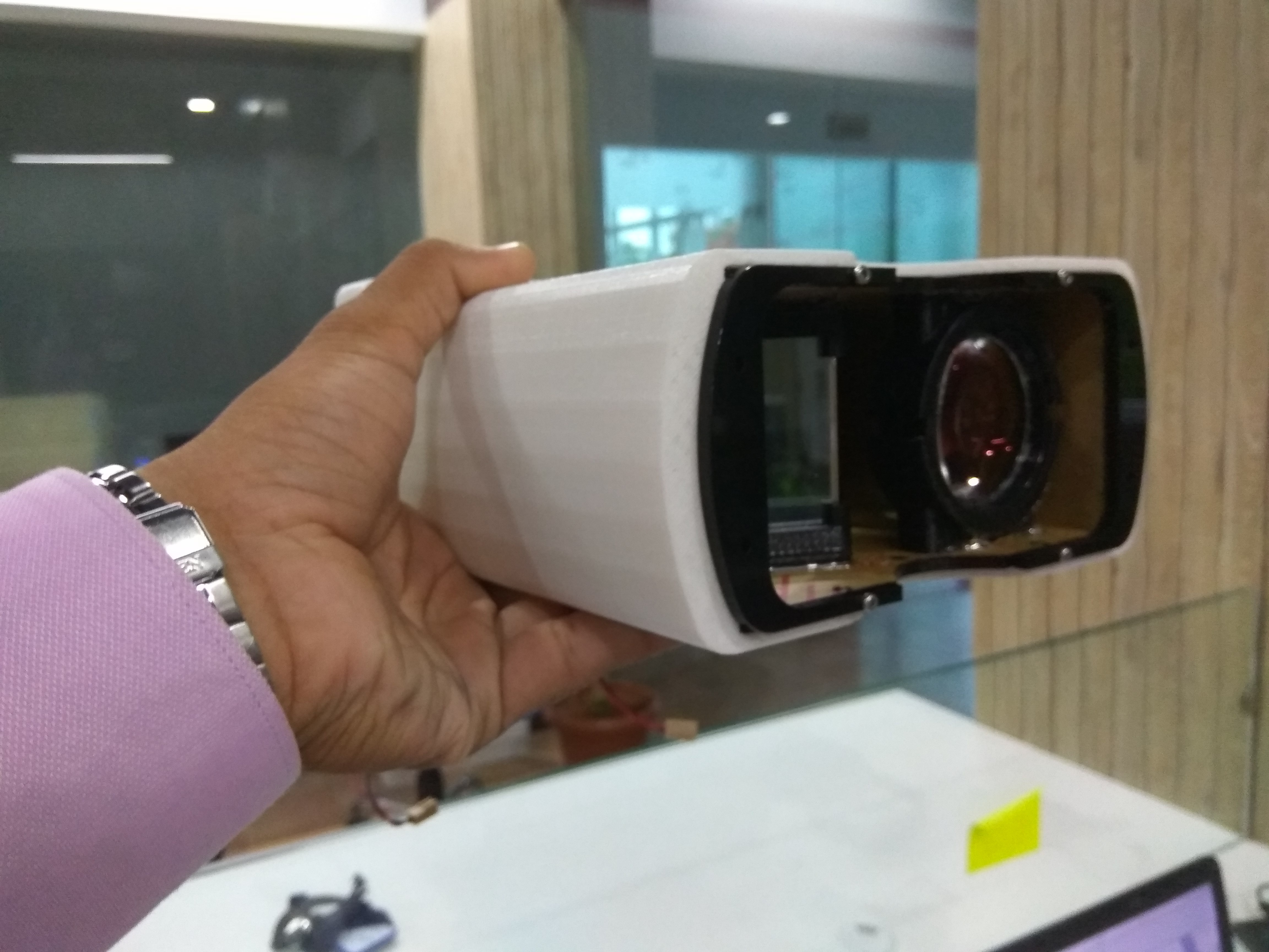
![]() And this is how it roughly looks from the eye, when switched on.
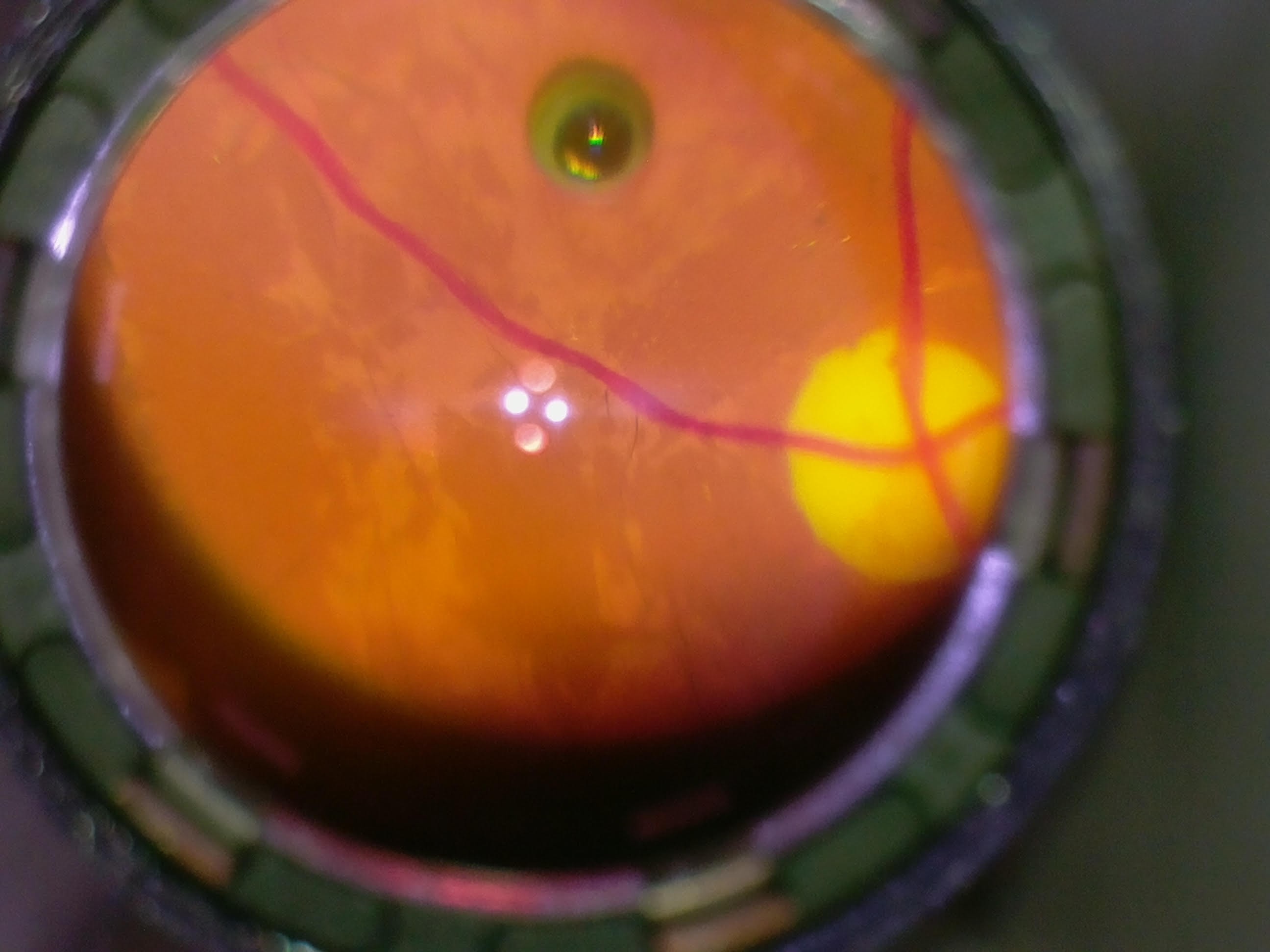
And this is how it roughly looks from the eye, when switched on.![]() This is a testing of the device during the assembly. The retina doesn't exactly look like a piece of art, but that is because the test wasn't done with the optimal distance maintained, it was only a test for the switches and the screen display.
This is a testing of the device during the assembly. The retina doesn't exactly look like a piece of art, but that is because the test wasn't done with the optimal distance maintained, it was only a test for the switches and the screen display.Better images and output of the device will be updated on the log later.
-
Fixing issues with Rpi.GPIO
06/01/2016 at 11:34 • 0 commentsWhile working on improving our code, our Pi's SD card crashed unexpectedly. After doing a reinstall of Wheezy, we found we were getting the following error on using Rpi.GPIO
No access to /dev/mem. Try running as root!We used the following linux commands to fix it
sudo chown root.gpio /dev/gpiomem
sudo chmod g+rw /dev/gpiomem

sudo chown root.gpio /dev/mem
sudo chmod g+rw /dev/mem
These commands gave gpio, access to mem and gpiomem which cleared the issue. But these had to be re-executed on each reboot. So we made a bash script for it, permission.sh.
After that we ran the following commands to make it execute on startup
chmod 755 permission.sh
cp permission.sh /etc/init.d
sudo update-rc.d permission.sh default
chmod +x /etc/init.d/permission.sh
Copying to /etc/init.d gets it executed on startup. The next two commands are to unsure the script is added to startup and to make it an executable script.The permissions issues were fixed but now, we were getting a runtime error in our python code on trying to run the Rpi.GPIO.wait_for_edge(). After a lot of futile attempts to fix the issue, we decided to use another gpio library, pigpio.
-
Completing hardware integration for portability: Touch screen and power bank
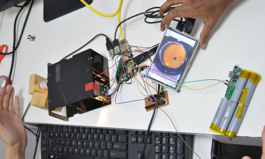
05/30/2016 at 15:09 • 0 commentsNow that we have a working form factor, we need to add all components which would make it portable - i.e. a power bank for powering the LEDs and raspberry PI and a touch screen interface (via HDMI). With these components integrated and working perfectly, the next step is to build the housing and form to incorporate these components into a single device.
![]()
-
Glare removal and optimizing illumination
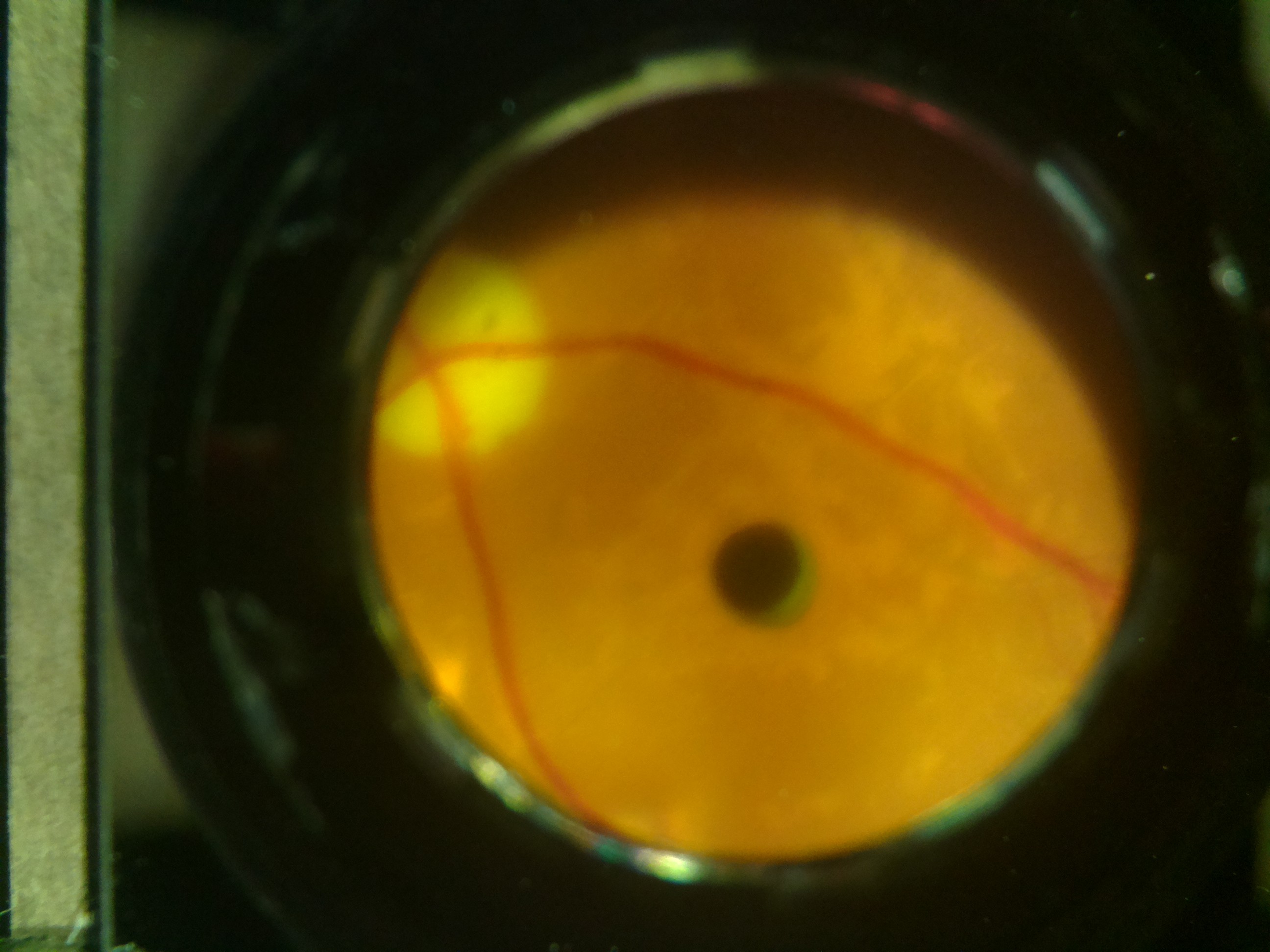
05/30/2016 at 14:49 • 0 commentsWe decided to use linear polarizers to remove the glare. Polarizers are often used for this purpose - we used a linear polarizing sheet from Edmund Optics. We'd have to use them in pairs, so that one polarizes our light source (white LED) and the other one polarizes the light coming to the camera in a perpendicular direction. This completely eliminated direct reflections (see image below).
![]()
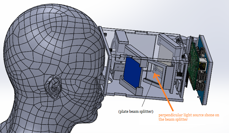
We also decided to use a beam splitter (50R/50T) to illuminate the system on-axis with the camera - this would eliminate the shadowing effect coming from off-center illumination (as in the image above).
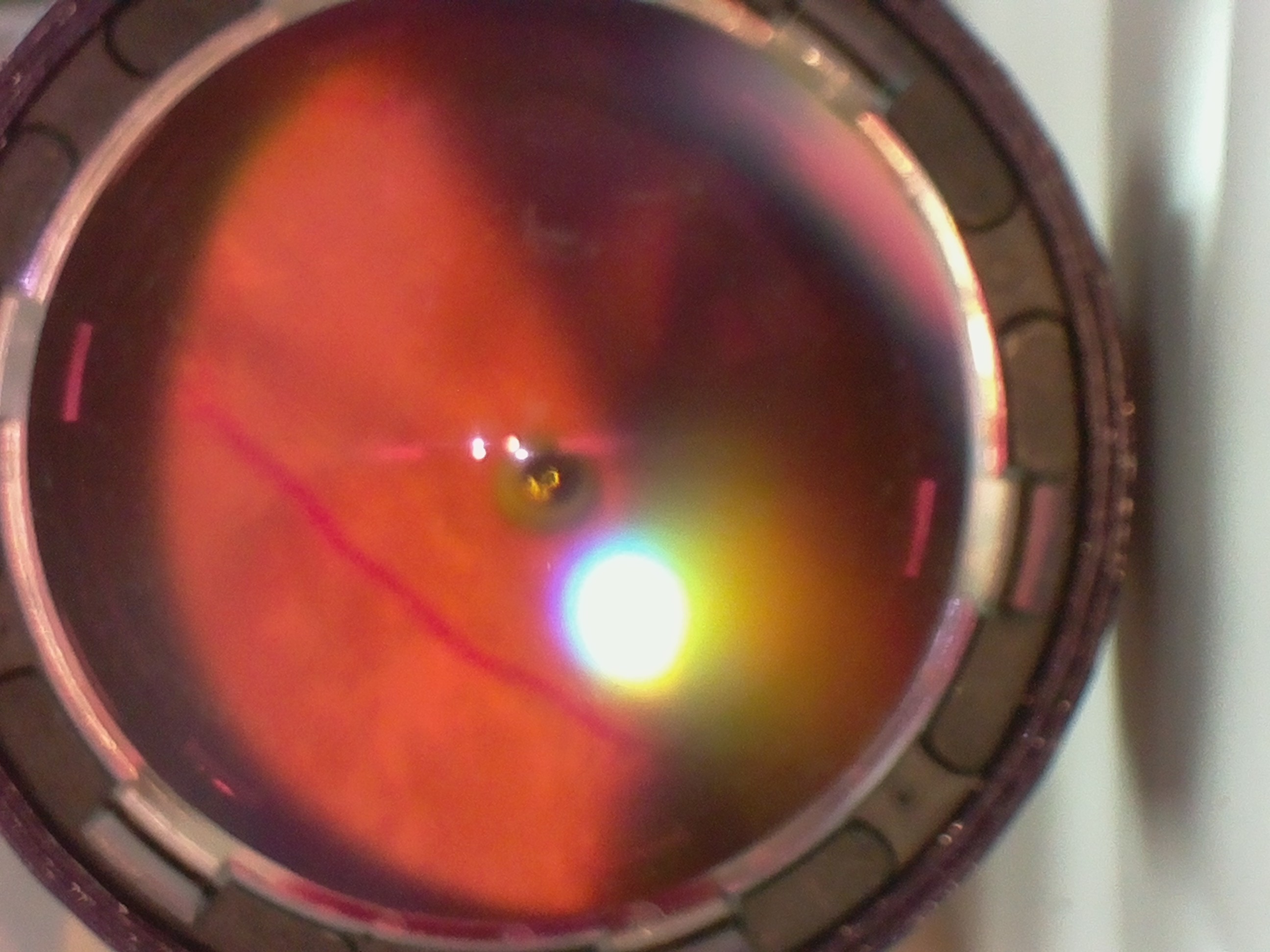
However, we observed that this caused direct reflections from the cornea (the transparent layer of the eye - such as the bright spot in the image below).
![]()
Hence we decided to retain off-axis illumination, but use two LEDs to illuminate from opposite off-axis directions - this would give two images of the same scene which were obliquely illuminated - i.e. having a "dark crescent" on the top and bottom respectively. We can then stitch these two images together to give a complete, evenly illuminated image of the retina.
-
Compressing the system: Using clever optics to make the system compact
05/30/2016 at 13:52 • 0 commentsOur system in its present form was pretty cumbersome, so our first task was to make it more compact and easy to use. We settled on a binocular form factor, similar to virtual reality glasses or binoculars, since this is more intuitive and comfortable.
![]()
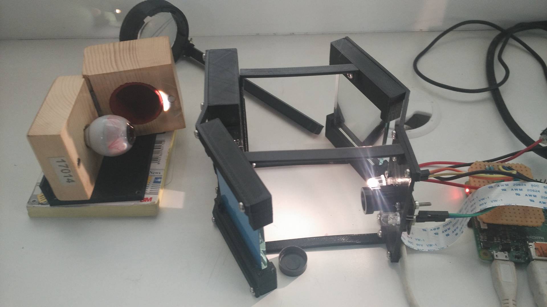
We used two mirrors to accomplish this. The image remains the same, only the construction of the device changes. In the schematic below, the two mirrors are placed at a precisely calculated angle at which we get the same image from the system.
![]()
We have now transformed the device into a "binocular" system - in reality, it would only take an image of one eye's retina at a time - which is fine as long as our device is symmetrical about the horizontal axis - which means you can flip it over and use it to image the other eye's retina. We also decided to use laser cutting to build a plate for the optics, onto which the mirrors and lenses could sit using 3D printed parts.
With the basic form in place, we now move on to removing the glare and the shadowing issue with the illumination.
-
Starting out: Mimicking an indirect ophthalmoscope
05/30/2016 at 11:27 • 0 commentsIndirect opthalmoscopy is a commonly used technique by clinicians to view the retina of a patient, using a condensing lens with a power of 20 Dioptres ("20D lens").
![]()
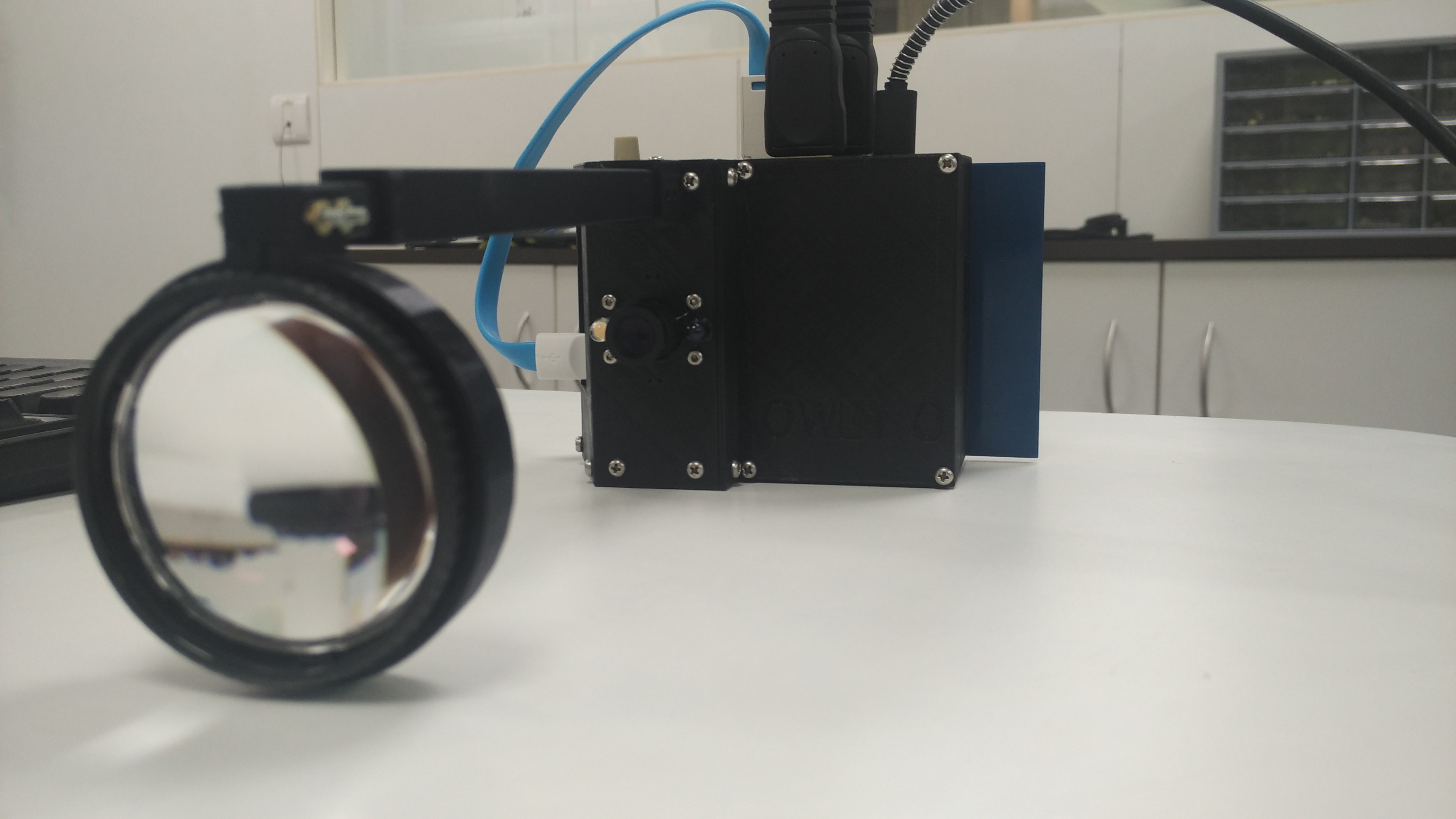
Our team decided to start here. We used a low-cost disposable 20D lens (Sensor Med Tech) and a 3D-printed housing for the raspberry PI (rPI), camera and screen. We used a raspberry PI camera with an M12 lens mount so we could use off the shelf CCTV lenses with a narrow field of view (16mm focal length lens in our case).
![]()
To view the retina, we need to shine a collimated beam of light into the eye, through the pupil. But this naturally causes the pupil to constrict, which reduces our view of the retina and makes it very difficult to use an Indirect ophthalmoscope. The medical fraternity gets around this problem using dilating drops - eye drops which temporarily relax the iris and artificially dilate the pupil for a few hours. This causes blurry vision for a few hours and is something we wanted to avoid.
We instead decided to use a simple workaround: Using infrared (IR) illumination to look into the retina (in a dark surrounding). Since IR is invisible to the human eye, the pupil should dilate in the darkness and allow a large portion of the retina to be visible. At this stage, we would flash a white LED (3200K colour temperature to mimick incandescent illumination, similar to the spectrum of light used in state of the art devices) and quickly take an image while the pupil was still dilated.
Rather than get started testing on patients right away, we decided to test our system out on a model eye (Gulden Ophthalmics). We observed that we could get a clear retinal image when the distance between the 20D lens and the camera was at an optimum of 270mm. At this distance, the retina view occupied the maximum portion of the field of view of the camera.
![]()
Issues to work on:
1. Removal of glare (the shiny points at the center of the image) caused by the 20D lens
2. "Crescent" shadow at the bottom caused by off-axis illumination
3. The entire setup was very long and clumsy. It would be better to compress it into a smaller product.
4. The tiny screen of the rPI could not allow us to view small details while debugging.
Open Indirect Ophthalmoscope
An open-source, ultra-low cost, portable screening device for retinal diseases



 The three parts are easy to snap-fit, but also have screw fixes just to make it safer.
 And this is how it roughly looks from the eye
 This is a testing of the device during the assembly. The retina doesn't exactly look like a piece of art, but that is because the test wasn't done with the optimal distance maintained, it was only a test for the switches and the screen display.