-
Well, Dang, It Doesn't Work
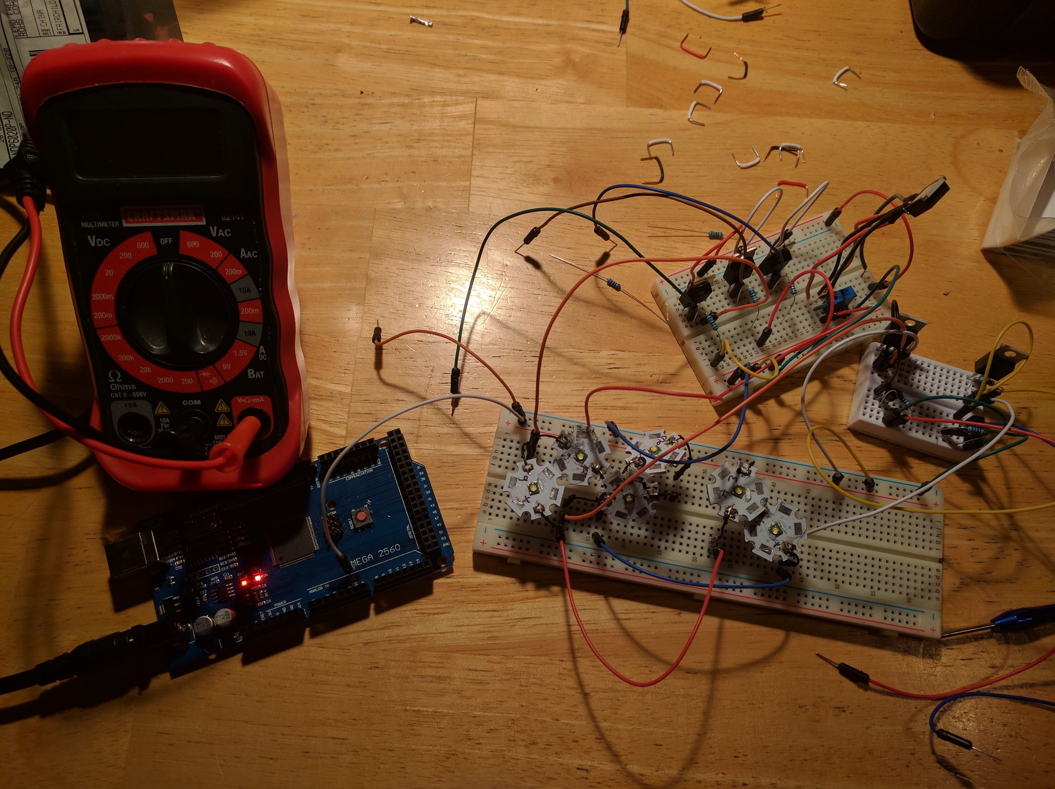
11/10/2016 at 00:45 • 0 commentsLogged about a possible alternate approach to the low-side LED matrix driver, where I use n-channel MOSFETs to switch on the LED, and a single CAT4101 to gate/control the current running through all the n-channel MOSFETs. Seemed to work fine at low to moderate currents, so I thought I'd prototype the low-side driver board using this design (cheaper than my original, and easier to work with). Before I did, I thought I should probably check it on a breadboard at the maximum current of 1A. Well, it doesn't get to 1 A; the best I could do was 0.8A, which is probably OK for most applications, but I still want full power. I suspect that there's some issue with the I-V characteristic of the MOSFET that's causing the current to saturate prematurely at a lower level. I may revisit this at some point in the future, but for now, the low-side driver board design will stay fixed with 8 CAT4101s both switching the LEDs in the matrix rows and controlling the current.
-
Back From Superconference 2016
11/07/2016 at 20:41 • 0 commentsBack from the Superconference. I'm a reasonably smart guy, but being in the company of those attendees made me feel totally inadequate - a massive amount of brainpower and expertise on display, but in the friendliest and most self-effacing of ways. Glad I went.
Given the competition, I was blown away by winning second place. My thanks to the judges for evaluating my project so highly, and to the entire Hackaday staff for running the competition and Superconference.
My second-place award was announced by Dr. Christal Gordon, who made a useful suggestion to me. The target audience for my gizmo includes museums and schools that may not have the making expertise required to build one of these, even with my OCDishly-comprehensive instructions. She suggested that a local group of makers could help these institutions out by getting together over a weekend, and cooperatively building such a system. One of my project logs discusses this very briefly, but I'll be adding a more comprehensive breakdown/flowchart of how a system could be assembled quickly by a group of makers by parallelizing the build.
Even though I've won a prize, this project isn't done yet. I still have some loose odds and ends to complete, and the documentation needs to be assembled into a coherent manual for assembly. I have some longer-term plans as well, but still have to figure out how to do them. Stay tuned for more. And if you're building a system, please let me know, and don't hesitate to contact me if you need help or advice.
-
Nuts. And the Superconference.
11/03/2016 at 01:24 • 0 commentsHad just made it to the last stage of assembly (or so I thought) of an advanced stand for the RTI-Mage. While the simple stand is OK for basic stuff, the advanced stand lets you do lots of cool stuff:
- Stick the system in a backpack/case, and take it on the road.
- Use a micrometer for accurate positioning during macro lens or microphotography.
- Image objects on a lab jack, just like the simple stand.
- Simplify swapping small objects in and out of the system.
- Mount the dome vertically, to access the surface of objects too big to fit under the dome (pots, paintings, fossils, whatever).
Got to the very last stage of assembly, which is creating supports to hold the dome vertically. But they didn't seem to fit the way I thought they should. Went back to the previous stand of this design that I built 1.5 years ago. D'oh! Forgot about a crucial design detail that makes that possible. Now I have to re-make one major part of the stand, before I can get back to the last stage.
Unfortunately, as with all the other small remaining details, this will have to wait until I get back from this weekend's Hackaday Superconference in Pasadena. Most of the items on my short-term to-do list from a few weeks ago are still there, along with the addition of prototyping the new low-side driver board. All will have to wait until at least next week. On the plus side, I did post instructions for adding Bluetooth HID shutter support to the controller recently, so at least one item has been checked off.
If you see me floating around the Superconference, feel free to say hi and ask questions. Along with other attending semifinalists, I'll be doing a 5-minute lightning presentation on this project. Regardless of whether I win any of the prizes or not, I will finish the short-term basics of this project. And, given enough time and/or money, I hope to follow through on some of my long term plans for this project.
-
Well, Dang, It Does Work
11/02/2016 at 21:12 • 0 commentsTested out the new low-side driver design with a 3 row / 2 column matrix design, and after the usual screw-ups and bad connections, found that it seems to work mostly as it should. One oddity was a very brief transient spike in the P-channel MOSFET that caused a brief LED flicker in the second column in a row. Adding a one millisecond delay at a key point in software got rid of it entirely. I suspect it's due to a small difference in power source wiring in the breadboard vs. that in the controller box, and that the delay won't even be needed in the final controller version. But even if it is, 1 millisecond x 64 LEDs = .064 seconds = trivial increase in total data acquisition time.
Next step is to build a new version of the low-side driver board, to test it in the actual controller. I'll take pictures, and be ready to revise the documentation, if it does work. I really hope it does - cuts the cost significantly, and makes the controller easier to work with.
Unfortunately (or fortunately, depending on how you look at it), I'll be going to the Hackaday Superconference this weekend in Pasadena, so in all likelihood won't be able to test this out until next week.
-
Looks Good So Far
11/02/2016 at 05:48 • 0 commentsThe new design, with a single CAT4101 as the current gate, works fine with a single low-side N-channel MOSFET, and with a single high-side P-channel MOSFET and low-side N-channel MOSFET. Just have to finish breadboarding a simple 3 row x 2 column matrix of LEDs to test that configuration, plus write a simple program to drive the matrix. If it seems to work, then I'll build a new simplified low-side driver board with the new design. Should know by tomorrow...
![]()
-
Hmmm. A Better Design?
10/24/2016 at 19:12 • 0 commentsAs with many other projects that control multiple LEDs, my system uses an LED matrix to control a maximum number of LEDs with a minimum number of inputs/outputs:
![]()
In my system, to get as high and controllable a current as possible, I use p-channel MOSFETs for the high-side switch controls (columns), and CAT4101 LED Drivers to control both the low-side switches (rows) and set the output current to a specific value:
![]()
This configuration requires 8 P-MOSFETs, and 8 CAT4101s. The P-MOSFETs are cheap at about $1 apiece. The CAT4101s are not so cheap - chip costs about $2.70 each, the breakout board about $2, and the trim pot about $0.50 (resistor and capacitor are trivial in comparison). That means a total cost of over $42 for all the CAT4101s. Plus, you have to set the current for each CAT4101 channel individually. That was my design decision right from the start in 2013, and I've stuck with it through multiple iterations.
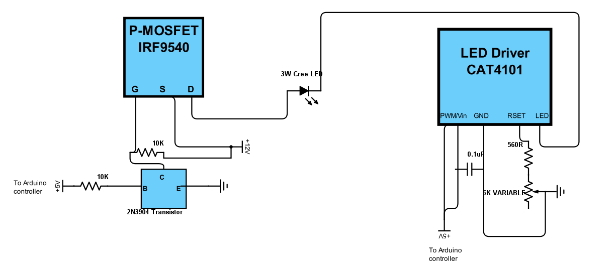
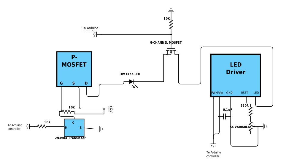
Was lying in bed early one recent morning, and had a thought. What if I created a matrix with 8 N-channel MOSFETs controlling the low-side, and connected the source for all of them to a single CAT4101 chip complex that connects to ground? Something like this (shown for only one LED):
![]() If it works, and I don't see why it shouldn't, it would have multiple advantages:
If it works, and I don't see why it shouldn't, it would have multiple advantages:1. 7 fewer CAT4101s, for a savings of about $36. This partially offsets the $8 extra cost for the MOSFETs; a logic-level IRL540 costs about $1 apiece.
2. A lot less soldering associated with the MOSFETs than the CAT4101s. No need for a variable resistor, capacitor, 560R resistor, ground connection, etc. Just current inputs/outputs, gate connection, and a 10K resistor to drain off excess charge from the gate to ground when unbiased.
3. Far cheaper addition of more output channels (in a potential future design).
4. Far cheaper increase of output current capability by paralleling two CAT4101s together. In the current design, you'd have to double the total number of CAT4101s from 8 to 16, at an additional cost of about $42. In the modified design, you double from 1 to 2, which would double the max current to 2A at an additional cost of only about $5.20. This would require a PCB board to handle the extra current, as I don't think every current part of the system could handle the extra current.
5. Instead of having to adjust system current for 8 CAT4101s, you only need to set it for one.
6. The CAT4101 allows adjustment of LED intensity with PWM. I didn't include that capability with my original design, as it would have required a lot more connections to CAT4101s (and I was seeing weird interference effects when I tried it). With a single CAT4101, that becomes a practical option for controlling light intensity, far easier than adjusting current.
I definitely need to test this first on a breadboard with small matrix (2x2 or 3x3) to see if it works. If it does, I think I have most of the components necessary to build such a board, and it would plug into my current system with no compatibility issues. I'll keep you informed.
-
RTI With A USB Microscope
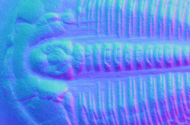
10/24/2016 at 17:13 • 0 commentsJust posted instructions on adding the ability to fire a camera shutter from a computer program, using an Bluefruit EZ-Key board to send keyboard/mouse commands via Bluetooth. This could be useful if you're controlling a camera from a computer program instead of using the shutter remote; Canon and Nikon both make such software for their DSLRs. I've been using it instead for image capture with USB microscopes; these don't come with remote shutter capability, but do come with software that controls capture either with a keyboard command, or by clicking a "capture" button in the interface. Here's a video (sped up 4x) showing a capture sequence for a trilobite (Elrathia kingie, to be specific; Middle Cambrian, Wheeler Shale, Utah).
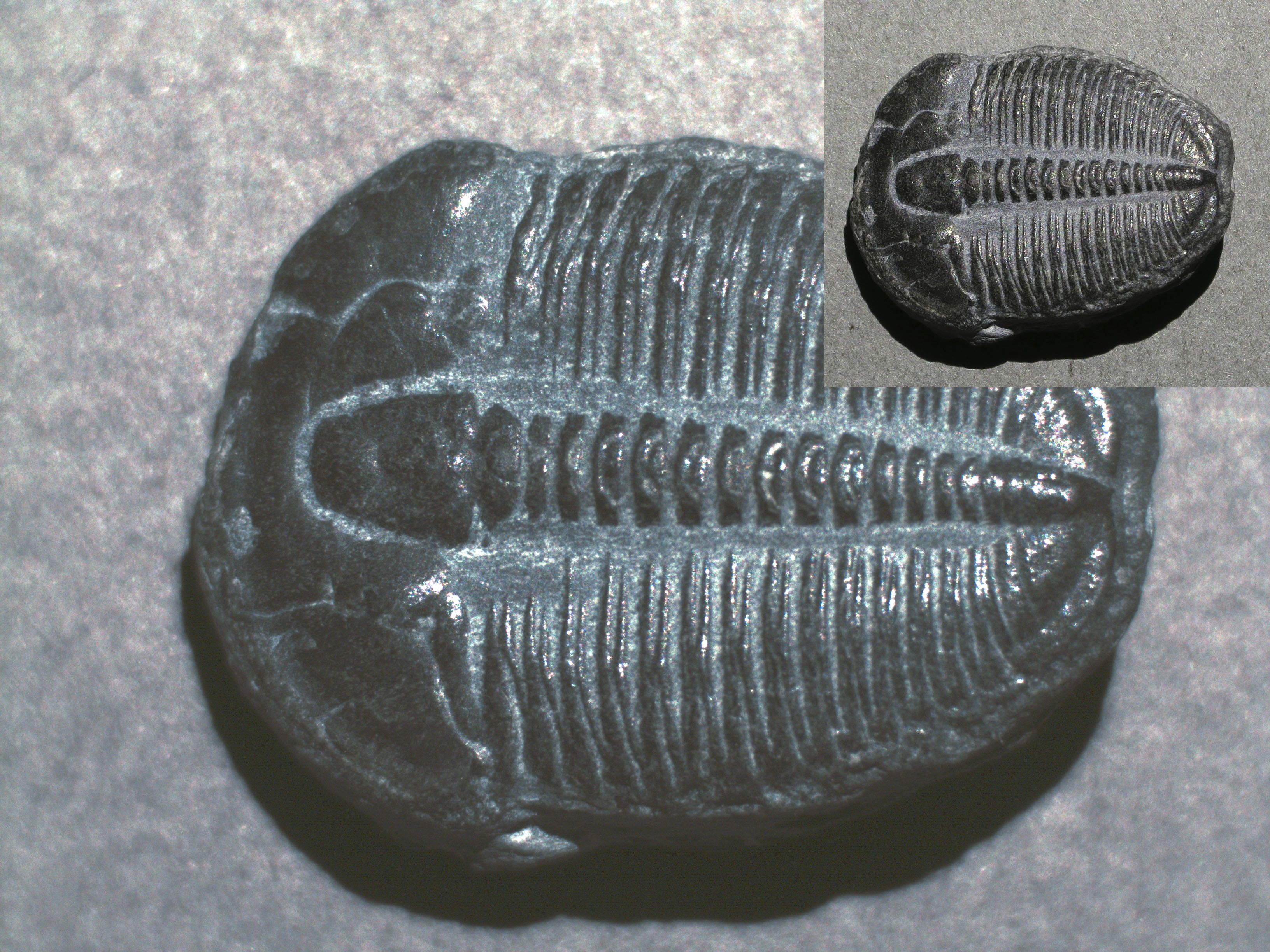
Here's a photo from that shoot, with the USB microscope image filling the full-screen, and a photo from my Canon S110 at maximum zoom as the inset. Both are at scale with respect to each other, compensating for the difference in image sensor resolution (8 MP for the USB microscope, 12 MP for the Canon).
![]() Bigger is better, right? Not necessarily. Generating RTI data for both sources, and zooming the images to comparable scales, I get this for the USB microscope (normals mode):
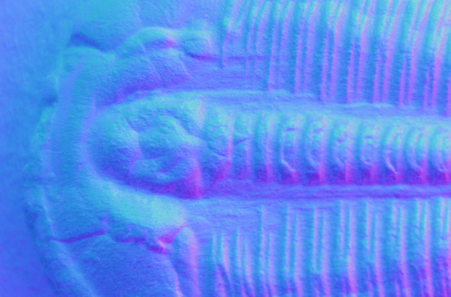
Bigger is better, right? Not necessarily. Generating RTI data for both sources, and zooming the images to comparable scales, I get this for the USB microscope (normals mode):![]() And this for the camera:
And this for the camera:![]()
While the original image dimensions are greater for the USB photo, the camera photo shows more detail. Don't know exactly why this is the case. The camera could have a better sensor/optics, camera autofocus might be more accurate than my manual focusing of the microscope, camera could have better of depth of field.
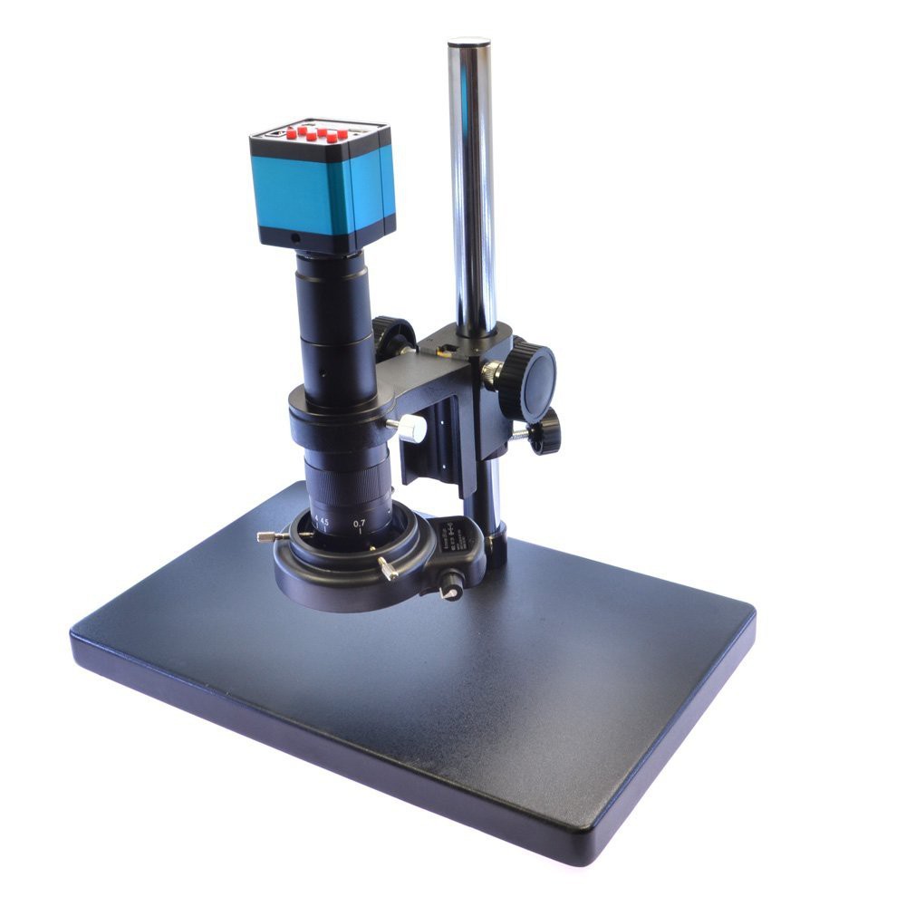
The USB microscope image was taken with the trilobite filling the full field, corresponding to a zoom level of 30x on the microscope. The microscope can go up to 200x, but there are problems with this. The higher the zoom level, the closer the microscope has to be to the object being photographed. And that can result in the microscope cylinder physically blocking light from the upper rows of LED from reaching the artifact. For the model of USB microscope I use, 50x power blocks all lights from the top row of LEDs; 100x blocks the top two rows; 150x and above blocks the top three rows. There are six rows in total, each with 8 LEDs, so for the highest magnification half the LEDs (24) are blocked. You can still get usable results with as few as 24-30 LEDs, but they're not optimal.
The setup in the video above has the USB microscope mounted in a telescope eyepiece focuser, since the dome is too small to house the microscope internally with its original stand mount. However, with larger domes (18" in diameter and up), you can put the microscope and stand underneath the dome. Since larger domes can have more rows of LEDs, there will be more light angles reaching the object. However, you can run into issues with parts of the stand blocking some of the LEDs. I hope to have software out soon that will simplify the processing of datasets with blocked lights.
Another option would be to find a USB microscope with a longer working distance; the further the microscope objective is from the object being photographed, the less likely it is to block LEDs. This is the model I'm currently using (which I paid $95 for), which can block up to half the rows; its working distance at highest magnification is about 3" (7.5 cm). This model, or this model, lists a working distance of 10.5-11.5 cm (about 4.6" max), which should result in less blocked lights. The camera sensor also has a resolution of 14 MP vs. my current USB microscope with 8 MP, which should improve overall resolution. Now I have to figure out a way to justify the substantially higher cost ($350+).
![]()
What's the conclusion? Not sure yet. I think that if you have a high-quality DSLR and a good macro lens, you should use that for now, as that will likely give you the best results; the drawback is the much higher cost for that (over $1000 for a decent DSLR and macro combination). It's possible that the higher-quality/longer working distance USB microscope might give even better results at an overall lower cost, but I'm not sure. If anyone would like to buy me one of the more advanced microscope systems so that I can check it out, I won't say no :).
-
Battery Life
10/21/2016 at 23:31 • 0 commentsThe small 12" dome whose build I documented here was mainly designed to be a portable system, for use outdoors in the field as well as for visits for museums, archives, collections, and so on. Since there's not likely to be a power outlet in the middle of nowhere, and power outlets may be difficult to access in other locations, the system can be operated off of a battery pack. In the components list, I specify a 6-AA battery pack for alkalines, and an 8-AA pack for NiMH rechargeables. But I've never actually tested how long the system can run just on battery power, using these two options. So, I thought I'd give it a try.
Conditions: The LED current is set at 350 mA, which results in a light intensity more than bright enough for short exposure times with such a small dome. The system has 48 LEDs, less than the maximum of 64 supported by the controller. The LEDs are on for 1 second, which is more than enough for any exposure conditions, even with the aperture stopped down for better depth of field. The camera is not attached, but the current draw for shutter control is likely to be insignificant. The endurance program is set up to run 100 sets of LED series at a time, so I may not get the exact count before the system runs out of power. The alkaline batteries are standard type, rated capacity of 2900 mAh; total battery pack mAh is 17,400 mAh. The NiMH rechargeables are charge-retaining (like Eneloops), rated capacity 2200 mAh; total battery pack mAh is 17,600 mAh.
Results:
Battery type # of full LED series Battery pack voltage at shutdown 6 AA alkaline 520 5.1V 8 AA NiMH rechargeables 360 6.5V This was a surprise to me. Standard alkaline batteries have a higher output resistance than NiMH, and given that the system draws a fair amount of current, I expected that the NiMH batteries would have lasted longer. But the standard alkalines lasted almost 50% longer. It's possible that at the highest current levels of 1A, the results might shift somewhat in favor of NiMH, but I'm not going to try that. The system will work with 8 AA alkalines, so I may drop the 6 AA battery pack as a recommended power option, and just stick with the 8 AA battery pack option.
NiMH are still recommended, though, since in the long run you'll save a lot more money using them than disposable AA alkalines. 360 artifacts photographed with 48 LEDs is almost certainly more than anyone could reasonably do in a single day; you'll run out of camera batteries and SD card space before the system quits on you. With 64 LEDs, that works out to 270 artifacts, still a ton.
-
Plans For The Short Run
10/10/2016 at 16:43 • 0 commentsNow that the rush to finish the basic requirements for the 2016 Hackaday Prize is over, there are a number of action items I need to take care of. I'm about to take off for 8 days of fieldwork with no Internet access, and I'm also a bit burned out by the last few weeks of effort. But I will get it done, I promise; I'm not going to abandon the project just because the Prize deadline has passed.
- Develop the servo option for an automatic shutter. Parts are here, just have to engineer it.
- Write-up the Bluetooth HID option for the shutter. This is pretty much done, just have to write it up.
- Write-up the construction of a portable stand. It's actually more than just a portable stand, it also configures for microscope/macro lens work, and vertical dome configuration for larger objects. The stand is about half-constructed right now, just have to finish making and documenting the construction. I've already built one of these, so I'm not doing it from scratch.
- The instructions/PDF manual need to be edited/revised/corrected/whatever. The PDF manual in particular is pretty rough right now. May have a chance to work on this in the field, since I can bring my laptop.
- I also want to add some sections that describe some of the image enhancement techniques I use on RTI images. The images alone are usually fantastic, but some simple enhancements can make them even better.
-
Instructions - Now In Easier To Swallow Format
10/10/2016 at 06:02 • 0 commentsThe instructions have gotten to be crazy long; over 42,000 words, and hundreds of pictures. I went overboard because I wanted people who hadn't done these kind of projects before to have as detailed a description of the construction as possible, to make it easier. But it's also made using the instructions on the website unwieldy - takes minutes for everything to download.
I have converted all the instructions, plus some critical log entries, into PDFs, and put zipped archives of them into the Files section. This is definitely a work in progress; right now they are pretty much the instructions/logs as-is, without editing for continuity or to remove redundancy. I will slowly move towards making all this documentation into a logically-organized manual. But for now, you can download these to your computer for much handier access than the online instructions.
Affordable Reflectance Transformation Imaging Dome
A simple and inexpensive way to image and analyze subtle surface details on objects.

 If it works, and I don't see why it shouldn't, it would have multiple advantages:
 Bigger is better, right? Not necessarily. Generating RTI data for both sources, and zooming the images to comparable scales, I get this for the USB microscope (normals mode):
 And this for the camera: