-
Modified Instruction Steps
09/16/2016 at 20:44 • 0 commentsPosted a log a while ago on an assembly screwup, where some soldered parts kept the Arduino shield from fitting properly in the Arduino. Now that the instructions are working again, have modified steps 4 and 7 to incorporate the fix.
-
Just "some LEDs attached to a camera"? Not exactly.
09/15/2016 at 01:28 • 0 commentsA post today on the Hackaday blog linked to a previous blog post on my project, so I took a look at that page for the first time in over a month. Bunch of comments about random technical issues, but one in particular struck me. The author said that my project was "not much more than some LEDs mounted to a camera", and that he could build a comparable system for less than $100. I had to smile - I used virtually the same words to a friend of mine three-and-a-half years ago when I started working on the idea, including that exact dollar amount. Turned out that there's a whole lot of complications that you don't think about until you actually start working on a project like this.
The main idea the author had was that you could use inexpensive addressable RGB LED strips like this one to simplify the whole process of controlling the lighting, as well as cutting the cost. Nice idea, but three big problems that aren't immediately obvious:
1. The LEDs on these 1-meter strips use 60 mA of current each (3.5 A strip total / 60 LEDs). I spent a lot of time figuring out how powerful the LEDs needed to be in order to light up a system up to a meter in diameter. My first thought was to power LEDs individually from Arduino Mega outputs, which limited me to 30 mA current (spec max is 40 mA, but it's recommended you stay away from that if possible). I tried "superbright" LEDs, in both straw-hat variety (wide uniform light dispersion), and focused (bright in the center, but narrow non-uniform beam). The straw-hats simply didn't have enough light intensity for reasonable camera exposure times even with smaller domes, a minimum of several seconds. The focused LEDs resulted in reasonable exposure times, but the small size of the lit area and its non-uniformity made them an unacceptable choice. Based on my initial experiments, I calculated that I needed at least 100 mA of current for reasonable exposure times for large domes with wide dispersion LEDs, and bought 0.5 W straw-hat LEDs for that. Turns out I was optimistic, and the exposure times for the first dome I built (18" diameter) were on the order of a second or more, which translates to more than 4 seconds for larger domes. And this was with the lowest f-stop I had; dropping the f-stop to improve depth of field could increase exposure time by a factor of 4 or more. An upgrade to 350 mA / 1W LEDs brought that exposure time to about 1/2 a second, which would translate to 2 seconds for a larger dome, but still not good enough. That's why I ultimately went to my current design, which supports 1 A / 3W LEDs, and could in principle be modified to double that. 60 mA LEDs just aren't powerful enough.
A recent paper by Ted Kinsman had similar results. He built his own independent RTI system (at least partially inspired by my results, based on his references). He uses an Adafruit LED matrix driver that supplies a maximum of 50 mA of current to his LEDs. With a 12" diameter dome, and a macro lens stopped down to f/8.0, his exposure times were 4 seconds, which translates out to 40 seconds for a one-meter dome. OK for a small dome, albeit a bit slow, but way too long for a big dome.
Why are big domes important? Because a rough rule of thumb is that the largest object you can accurately image with Reflectance Transformation Imaging is half the distance to the light source you're using. So for a 12" dome, 6" radius, that's 3". I think this is conservative, and you can do a bit bigger, but there's still a limit. Larger domes allow for accurate imaging of larger objects - a one meter dome can image an object about 10" in size.
2. When I was testing the 30 mA LEDs, I found that the variation in light intensity between different LEDs was as much as 20%. Reflectance Transformation Imaging requires that the light sources be as close to the same intensity as possible, otherwise the final result may be an inaccurate fitting of the light curve. I wasn't sure about the reason, but a bit of research brought up the most reasonable answer. While LEDs are sold with a quoted forward voltage for a specific current, what you actually get from a bunch of LEDs is a spread of forward voltages centered around the specification. Given how steep an LED I vs. V curve can be, a small change in Vf can result in big changes in the current, and big changes in the light intensity (see Grumpy Mike's excellent discussion of these issues). The current-limiting resistor commonly used with low-current LEDs is there to drop the voltage across the LED so that you don't burn it out, and not to specifically control the exact current. Given the low cost of the LED strip, I have to believe that it uses resistors to limit current to the LEDs, which could translate into substantial differences in output power between different LEDs. Not acceptable. My system has always used adjustable constant current regulators to get around this problem.
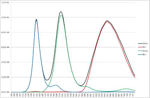
3. Finally, RGB LED strips create "white" light by turning on the red, green and blue LEDs simultaneously. While it looks "white" based on appearance, it's not a very good white. Here's a "white" spectrum from an RGB LED:
![]()
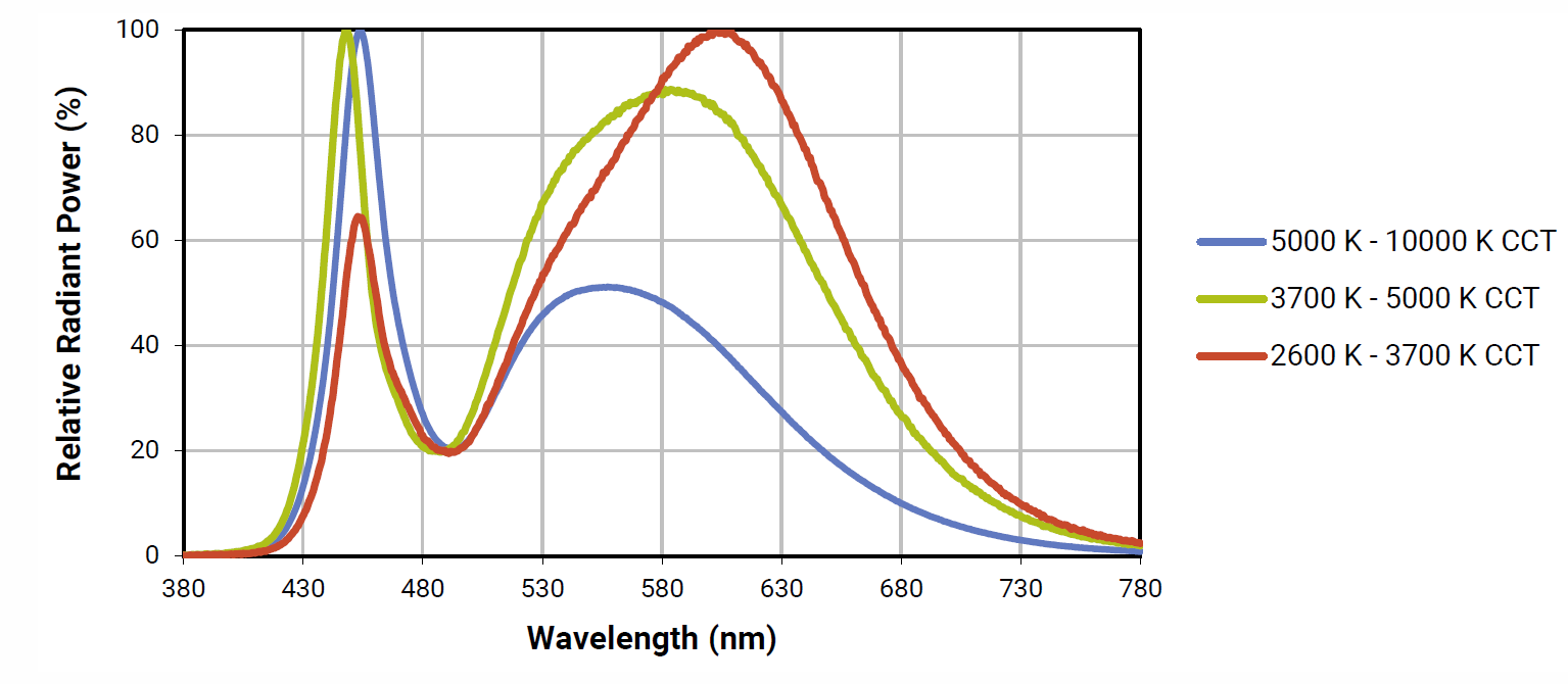
Not very uniform. Now here's a spectrum from a neutral white Cree LED (the green line), like the ones I spec for my system:
![]()
Much more balanced and uniform over the visible spectrum, with a peak near the blue end. This is easier to color correct than the RGB "white" spectrum.
There are other issues as well associated with the cost, like not including $36 shipping for the dome, or the fact that you'd need not just one LED strip to achieve the angular coverage needed for RTI, but more like 16, for a total additional cost of $170. Factor all those in, and you wind up with a system that doesn't cost that much less than the one I'm building, but has potentially serious or even fatal flaws, and can't be scaled up to larger sizes.
So is my system "not much more than some LEDs mounted to a camera"? I guess you could say that, but a hell of a lot more thought and effort went into that than you might think.
-
New Instructions Back On Line
09/12/2016 at 21:32 • 0 commentsBack from field work, and the issue with instruction steps not uploading seems to have been fixed. Just posted a new step now, and should have another three steps up by the end of the day. With luck, should have all the basic assembly instructions done by the end of the week.
-
Upcoming Schedule
09/05/2016 at 05:56 • 0 commentsI have four more instruction steps written up, waiting for a fix for the "Error 413" problem I'm currently getting when I try to post a new instruction. If I hear from Hackaday by tomorrow that they've implemented a fix, I'll post all those up. Otherwise, they'll have to wait until next weekend or early next week - heading out for 5-8 days of fieldwork (depending on weather) in the boonies.
Once I'm back though, instructions will come fast and furious. Getting the project documentation finished will be my top priority for the rest of this month. With luck all the build instructions will be up by September 20th, and all calibration/operation instructions done in the following week. I also hope to meld all the instructions and relevant logs into a single downloadable PDF; that should be a more helpful construction guide than having everything online. Hackaday deadline for the 2016 competition is October 5th, so I have a little incentive :-).
-
Display On Display
09/05/2016 at 05:48 • 0 commentsOn my previous RTI systems, the only feedback I get from the controller during the operation is a "beep" when each LED is turned on. Not a lot of information, and also not really necessary, since I get a shutter sound from the camera indicating that it's firing, which indicates that things are working. I've been thinking about adding a more useful feedback tool, and finally broke down and bought one of those little 0.96" 128 x 64 I2C OLED displays that you can pick up for less than $10 if you look. Adafruit has a nice tutorial on their use, along with sample code. Connected the board to a spare Arduino Mega I had lying around, uploaded the test code (after a few modifications), and it worked fine. Then hooked it up to one of my older RTI systems, and modified the control code to add display support. Didn't work. Spent an hour debugging code, checking connections - nope. Connected it back up to the first Arduino, and it worked fine. Hmmm. Grabbed the Arduino that will be controlling the current build being documented, uploaded the code, and tested it. Yup, worked. Sometimes it really is the hardware's fault.
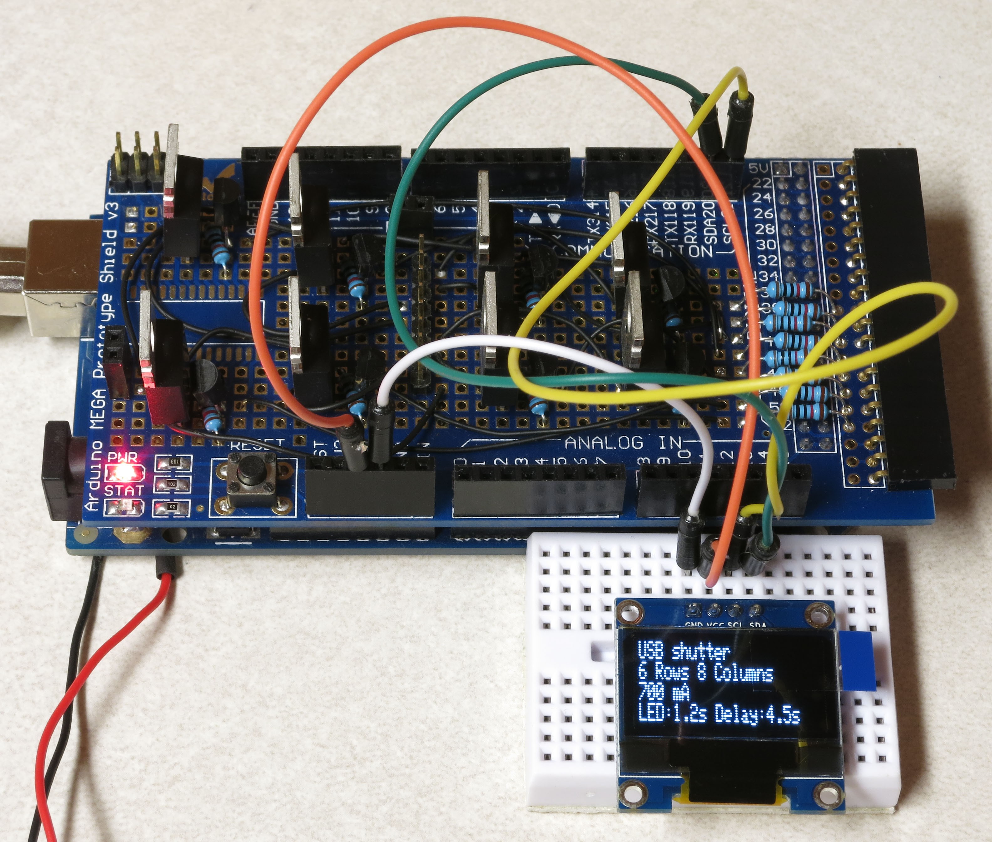
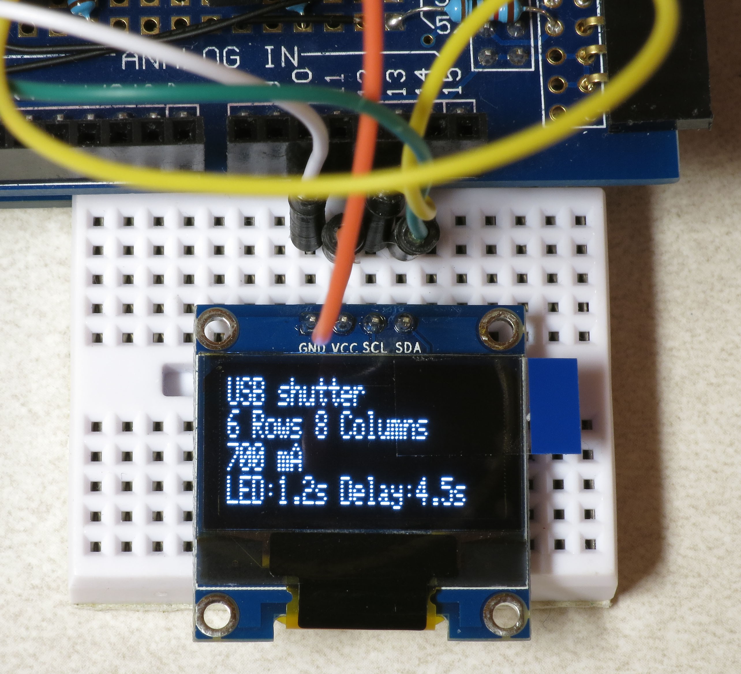
Anyway, here's a couple of pics of the display in action plugged into the MOSFET driver shield that's part of the new RTI system being built. Still have to figure out which parameters to display and how, but I'll get that working when the system is fully assembled. At a minimum, it will show how far along in the process you are, and how much time is left. Full instructions will be written up, including how to install it in the control box ... as soon as I figure out how to do that.
![]()
![]()
-
Problems Solved!
08/20/2016 at 20:58 • 0 commentsAll the issues in the previous log have been resolved, and the RTI control/power system has been tested, and is working!
What's going on here is that I have LEDs connected to matching high-side and low-side channels (i.e. high 1 and low 1, high 2 and low 2, high 3 and low 3, etc., all the way to 8). The Arduino is activating the matched channels simultaneously, which should turn on each of the 8 LEDs in sequence for 1/4 second, as well as setting off the beeper. The system can provide up to 1 A of current to these 3W Cree LEDs. When the lights are off, a +5 positive voltage is turned on to the USB and shutter servo control, which is checked with a multimeter. This setup also doubles as an LED tester, to make sure they're working, and are wired correctly.
Instructions for this step, as well as the Arduino software required, will be up in the near future. And construction of the system is now in the home stretch!
-
Putting the pieces together
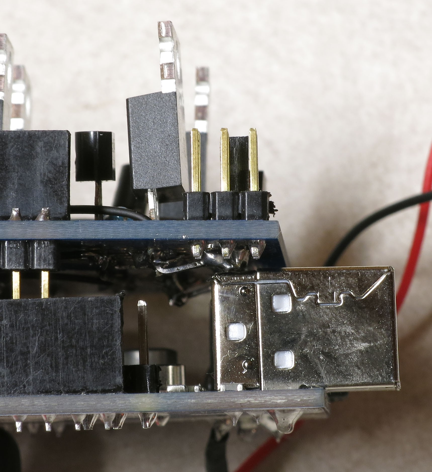
08/20/2016 at 07:16 • 0 commentsYou know that feeling you get when you put a whole bunch of system components together, and they work perfectly the first time? Yeah, me neither. At least, not tonight. First, I installed the MOSFET driver shield board on the Arduino Mega, and discovered that a clever enhancement I had thought up not only prevented the board from seating properly, but shorted out the power supply. Turns out I had forgotten that a section of the shield board sits flush against the ground shield of the Arduino's USB power, so you can't install any components there. I got fooled by the existence of component holes in a place where no components should go. So there were solder blobs and wires that shorted out on the USB shield, and prevented the shield from fully seating into the Arduino:
![]()
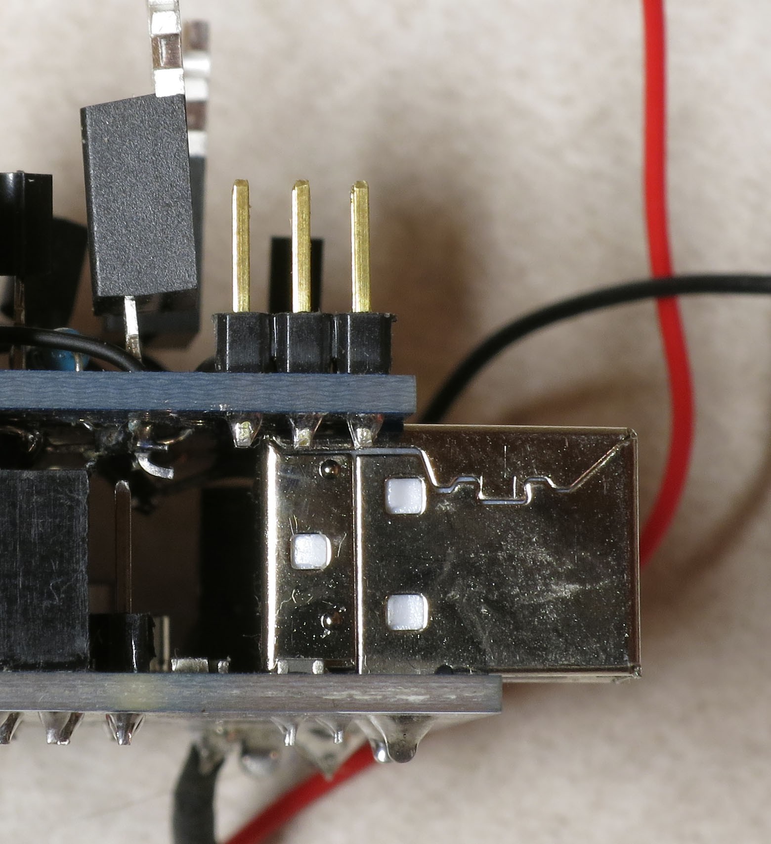
Removed the offending components and solder, and it fit with no shorts:
![]()
Fortunately, it was possible to re-route the offending connection so that it was well clear of the USB shield. I'll have to fix that in the instructions.
Then, the LED that was supposed to light up, didn't. Turned out that my Arduino IDE installation was corrupted on my main computer, and wasn't properly uploading the testing software on the Arduino. Switched over to a different computer, and the software worked, but the LED still didn't turn on. Finally found that one connector that should plug in snugly and securely was loose and floppy, and when I temporarily fixed that, the LED lit up. Yay. Haven't had that problem before, so I'll have to clip the wires off the connector, re-wire a new connector, and see if I can figure out what caused the problem. At least I know the system will do what it's supposed to do now.
And so to bed.
-
Bunch Of Instructions Coming Up
08/19/2016 at 05:29 • 0 commentsOut on fieldwork for the past week or so, with no Internet connectivity. But did have my laptop, so was able to work on writing up more instructions, and have started posting those. Hope to get a lot more up in the next few days.
-
Shutter Stuff Is Here
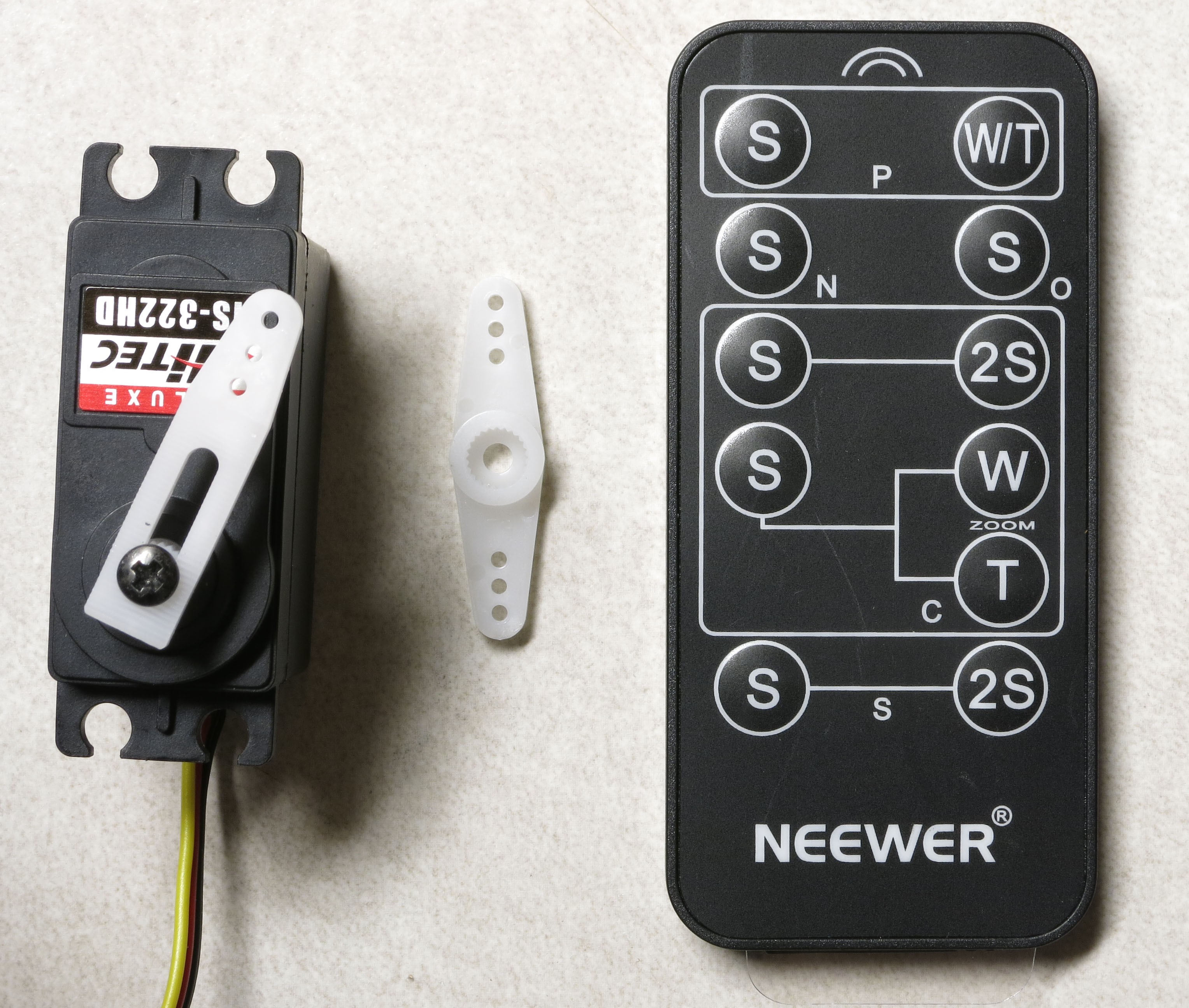
08/05/2016 at 03:48 • 0 commentsJust received the servo and IR remote I talked about in the last log:
![]()
Good news is that I think that I can get the servo to work as an automatic shutter for those cameras that don't support a remote control. But that will have to wait until I get the full build instructions done.
Bad news is, I don't think it makes sense to work on connecting the IR remote to the RTI controller. I had hoped there would be a single shutter button, and some kind of easy switch/configuration setup to let you choose which brand of camera you're using. Instead, looks like there's a separate shutter button for every brand (Pentax, Nikon, Olympus, Canon and Sony). Oh, well - it was cheap, and I'm sure I'll find another use for it. Will still be able to implement IR remote capability with an IR LED that plugs into the controller (and which I know works fine); just have to specify the camera brand in software, and upload a new version every time you switch camera brands.
-
Shutter Scramble
08/01/2016 at 04:34 • 0 commentsI'm getting to the point in the assembly process where I'm hooking up the interface that automates the camera shutter, and just realized I'd forgotten about my plan to add the option for mechanical triggering of camera shutters. D'oh!
The system currently has four ways to trigger a camera shutter automatically, in sync with the LEDs at different lighting angles turning on and off:
- Through a standard USB cable connected to a Canon camera that supports CHDK, with the CHDK settings set to allow shutter triggering with a voltage pulse through the +5V and G connections.
- For cameras supporting a wired remote, through the same USB cable connection and +5V pulse, this time using an optoisolator circuit to close a circuit and trigger the shutter.
- For cameras supporting an IR remote, a USB-connected IR LED driven by Sebastian Setz's Arduino IR remote library.
- For cameras that can be triggered via a PC program, the Adafruit Bluefruit EZ-Key Bluetooth HID adapter.
For cameras that don't support any of these options, there is the option to run in manual mode, where you push a button to light the LED for a second or two, press the shutter manually, then press the button again to advance to the next LED. Certainly works, and doesn't actually take much longer than the automated approach, but requires you to babysit the system - not fun. So I've had in the back of my mind to add a method to depress the shutter button that could in principle be adapted to any camera.
I've found a few electrical approaches online, where you disassemble the camera, find the shutter switch connections, and wire an electrical switch (like the optoisolator circuit in no. 2 above) to let you trigger the shutter with an Arduino or other electrical control system. Don't like that approach, since you have to take apart the camera and find the right place to wire the shutter connection, and you're permanently modifying the camera. I break things. A lot. The other approach is electromechanical, using a servo connected to an Arduino that will physically depress the shutter button. Lots of people doing this online, with an amazing variety of Rube-Goldbergian attachments. That's a compliment - I'll be lucky if my setup looks half as good as any of these.
The RTI system control box has a USB connector on the back side that options 1-3 above plug into, and I'd like to use that same connector for the servo. Those three options only need two electrical connections, for +V and ground. The servo needs three connections, +4.8-6V for power, +5V to control it, and ground. Options 2-3 would work fine with a permanent +5V connection, since they won't be connected to that line. But I'm concerned about a constant +5V signal through the USB port to the Canon camera using CHDK. It might do nothing, it might freeze up the camera, it might break the camera; don't have any interest in doing the latter. I thought about supplying +5V power to the servo with an Arduino output pin, but that's limited to a max of 40 mA, and a recommended max of 30 mA. I did find one page that suggested that might be possible, but the datasheet for the servo indicated that the servo could draw 160 mA in normal operation, and up to 700 mA in a stall, easily enough to blow out the Arduino pin. Had me stumped for a few minutes, until I had my standard "I'm a dope" revelation - just hook up a couple of header pins for use with a mini-jumper. Put the jumper in, and it supplies +5V to one of the USB output pins; remove the jumper to disconnect the +5V, and you can use the USB output with the Canon CHDK option without problems. If you get tired of putting the jumper on and off, you could even wire it to a switch mounted externally on the controller enclosure.
So, the servo is on order, and figuring out how to make it work is on the agenda after I complete the instructions for the full system. Gotta come up with a simple way of mounting it so that it can trigger any camera, calibrating the servo parameters, and adding the code to the controller system. Stay tuned. I'm open to suggestions.
While I was thinking about shutter issues, came up with an alternative to option 3 above. While the Setz library and the IR LED rig have worked fine on every compatible camera I've used them with, one problem with it is that if you change the brand of camera you use (Canon, Nikon, Sony, etc.), you have to change the IR remote controller code to match the brand (i.e. the codes for Nikon won't work for Canon, Canon won't work for Sony, and so on), then upload it to the Arduino. Flipping around on eBay, found a cheap IR remote that works with multiple brands; cheap as in about $3 for the one I ordered from the US for quick delivery, about $1.50 for one direct from China . If I can figure out how to open it up without breaking it, and then wire an optoisolator circuit to the shutter switch, that would be an easy way to have an IR remote that could easily be switched from one camera brand to another.
Affordable Reflectance Transformation Imaging Dome
A simple and inexpensive way to image and analyze subtle surface details on objects.