Close
0%
0%

SOLDERING IRON Very Precise & Super Simple

I started designing an intricate digital controller and in the processes I came up with an idea to make a basic analog controller.

Similar projects worth following
Very Precise & Super Simple soldering iron controller

A good engineer realizes that it needs good tools to create good products.
As I realized using my cheap chinese soldering station that the temperature was off an the time that it took for it to reach the set temperature was too long. As the professional soldering stations were too expensive I thought that I should design my own to address the problems and requirements that I expected from this project and in the process to learn about heating elements, thermocouples, precision amplifiers, PID and control.

This documentation describes Open Hardware and is licensed under the

CERN OHL v. 1.2.

You may redistribute and modify this documentation under the terms of the

CERN OHL v.1.2. (http://ohwr.org/cernohl). This documentation is distributed

WITHOUT ANY EXPRESS OR IMPLIED WARRANTY, INCLUDING OF

MERCHANTABILITY, SATISFACTORY QUALITY AND FITNESS FOR A

PARTICULAR PURPOSE. Please see the CERN OHL v.1.2 for applicable

conditions.

  • simple version

    insidecircuits05/29/2016 at 09:59 0 comments

    After doing some tests with the PID library I realised that this type of control might be overkill, and a simple comparator that enables the output when the temp is lower than the set point is enough. Still I haven't done the complete test yet as the precise temperature converter is giving me an error. So this is yet to be concluded.

    But this raised the idea that I can completely overhaul the whole design and create an alternative that can be super simple.

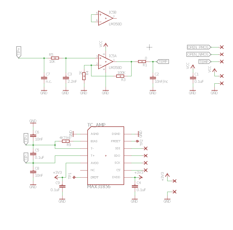
    I could use a analog precision op-amp to amplify the voltage of the thermocouple and output a voltage that represents the temp mapped as voltage: 10mV equivalent to 1 degree Celsius. Then a maximum of 450 degrees would output a 4.50V for example.

    This output will be compared to a voltage referenced to ground provided by a regulator. A simple trimpot will set the target voltage-temperature.

    So a second op-amp will act as a comparator and will do this operation, switching on the driving transistors when the temp is lower than the setpoint, then switching them off and perform the measurement to see if it's the case to switch them on and off again.

    A RC oscillator to create the loop and some low pass filtering will provide the stability of the system.

    The circuit will be entirely analog and the display part is made by measuring the voltage with a voltmeter, the simplest form of the controller involving only a couple of op-amps, resulting in a very simple and small board. Not the most useful but still very portable.

    Next I will continue to develop both circuits and compare the final versions.

    *both can be powered with a battery pack at 12V or trough a DC-DC converter at 24V 70W for full power.

  • testing

    insidecircuits05/29/2016 at 08:55 0 comments

    After assembling the board I quickly tested the MAX31856 with a library that I found on github and as it turns out the temperature reading was not as expected, checking the schematic I realized that I made a mistake and reversed the sensing lines coming from the thermocouple. Oops. Fixed that and temp was good.

    Next I thought of the control loop, the output signal would look like a PWM signal modified with a imposed fixed time at one end to take the temp measurement. The rest of the signal is composed of the duty cycle given by the PID library where we input the setpoint and the measured temperature from each cycle and it outputs a control value

    But first I had to see how the commuting between driving the element and measure the temp will behave and here I stumbled across problems. The library for MAX31856 enables the chip in continuous measurement mode and sets the error detecting flags for generating interrupts whenever something goes wrong like open connection to the thermocouple, over voltage etc. This gave me problems as even I disabled every flag for error reporting even after making the measurement an over voltage error would appear.

    The next thing I have to try is to start writing the code from scratch and set the IC in single shot measurement. If that won't work even powering the IC from a digital pin and shut it down completely (not the most elegant solution).

  • design

    insidecircuits05/29/2016 at 08:25 0 comments

    I started creating the schematic adding the MAX31856 and also included a simple op-amp (LM358) for backup just in case my solution won't fit together. The purpose of this is to directly amplify the voltage across the thermocouple and output a reading in volts proportional to the temperature.

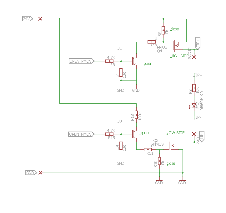
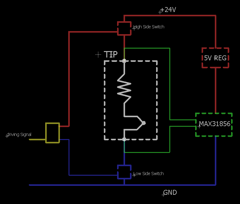
    For the switching part the best solution would have been some relays, to completely disconnect the tip while reading the thermocouple so no external voltage would drop on the junction. I was thinking of some reed relays that have longer life than traditional ones but I dropped the idea in favor of a more elegant solid state solution using MOSFETs. I had to use a N-channel on the low side and a complementary P-channel on the high side (to avoid charge pump complications driving a N-channel high side). Also I inserted two driving transistors, the low side one also acts as an inverter so that the command signal will open/close both sides at the same logic level.

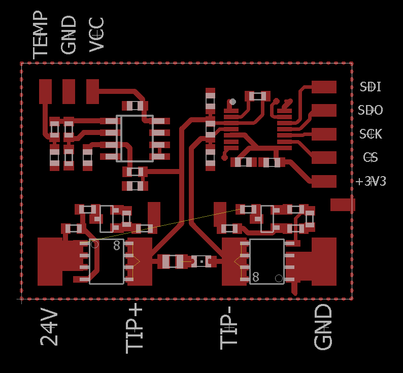
    Here is the layout of the board that includes all the components above. Actually there is a mistake here on the sensing terminals (they are reversed) so it has to be corrected.

  • concept

    insidecircuits05/29/2016 at 08:16 0 comments

    Having the components in mind I have to think of ways to connect them together, the requirements of each one and the restrictions that they impose.

    The soldering tip has only two terminals, that means that the heating element is connected to the thermocouple (in series).

    The implication of this is that we can't heat the element and measure the temperature at the same time, we have to do it alternatively, first we supply the element with 12-24V, stop, then measure the voltage across the terminals which gives us the temperature of the thermocouple, stop and start again with heating if it's the case. But this gives us some problems as the voltage difference is so high, the heating element is resistive and should not make problems by inducing currents after it has been disconnected.

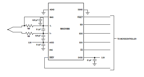
    Let's get to the thermocouple converter MAX31856. The first obvious thing is that we cannot supply 24V into this one while making a reading although it has ±45V input protection. The next requirement is that it requires floating connection of the thermocouple to make a precise reading, that means that none of the two ends should be connected to anything else (like GND or V+) while measuring temperature. Also as you can see in the typical schematic the BIAS pin introduces a voltage to make the reading.

    The conclusion is that we should have both a low side and a high side switch for driving the tip element that open/close at the same time.


  • choosing components

    insidecircuits05/29/2016 at 06:45 0 comments

    The first thing I did was choosing the components:

    I started with the soldering iron tip, I came across a model that has integrated heating element and thermocouple inside the metal body. My previous soldering station had detachable tips that can be replaced, that is convenient if you exchange the types of tips frequently but the problem I identified is that the heating element is not contacting the metal body of the tip perfectly so the contact area is small and the thermal transfer has to be low, as such the tip is not heating as good as it could be.

    The T12-D16 model of tip that I selected has the tip, heating element and thermocouple all integrated in the body as such it makes a compact part and resolves many of the problems from the beginning. It is also very light and got me to think that the final product may be portable! The disadvantage of this model is that it has only two external electrical connections, by making elegant the manufacturers imposed some engineering challenges to make this work. (I kind of like it).

    The next thing that comes is the precision, more exactly the thermocouple amplifier that reads the extremely small voltage produced by the thermocouple and amplifies it. I chose the MAX31856 as is the most precise (19-Bit, 0.0078125°C) I found and has an integrated ADC, cold junction compensation, input protection, 50/60Hz noise rejection (very important since the wires that connect to the tip assembly pic up a lot of EMI) and such removes a lot of overhead from our part.

    For testing I chose an Arduino board as it's enough processing power, for controlling the temperature I will include a PID library, the controller will have a OLED display to clearly show the temperature and have a few setpoints in memory that we can choose from. A rotary encoder will be the input interface.

View all 5 project logs

Enjoy this project?

Share

Discussions

Similar Projects

Does this project spark your interest?

Become a member to follow this project and never miss any updates