The chassis consist of multiple levels. On the first level there are the motors, and the battery. And currently a special part for the "Magyarok a Marson" competition.
The robot chassis made of PCB boards. The boards fixed with soldering. This make a solid base for the robot.
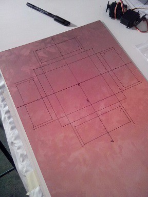
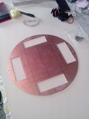
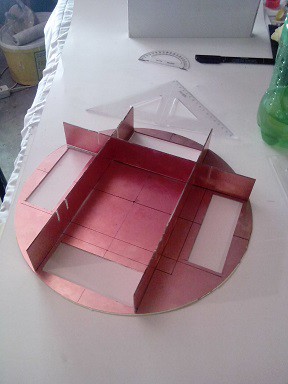
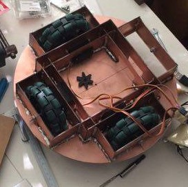
We used omniwheels because this way the robot can freely move every direction. There is some other solutions, but for our plans in the future, we need fast direction changing reaction. We selected the four wheel layout, because in the past we built a robot with three wheel layout, and we need more traction, and carrying capacity this time.
The chassis of the robot is designed to be able to carry lots of weight. We are using supported axles for the wheels, to reduce the stress on the servo motor.
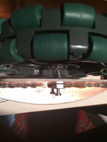
On this picture this is a screw, with a hole in it. We don't use bearings for now, but in the future, if we have some problems with this solution we will upgrade it.
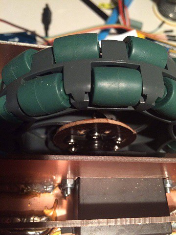
On the serve side of the wheel, we use a custom clutch. It's made from a thin plywood, glued with epoxy to the wheel. The servo adapter secure the whole part with screws. Mostly the support from the other side make it really stable.
We placed the battery the lowest point on the robot, to keep the center of gravity near to the ground.
It is possible to place two 12V 7Ah battery on the robot, but with one battery it can be used about 12 hours with one charge.
On the second level, above the battery there are the electronics. We used aluminium spacers between the levels. In the rectangular aluminum profile we used threaded rod with nuts.
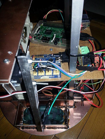
The second level floor made of plywood, so this way we can easily tie down the electronics.
On the left side of the picture there is a mechanical part from a CD drive. On the "Magyarok a Marson" competition we have to insert in the holes of PVC pipes, a signaler fixed to the robot "arm" (the aluminium stick connected to the CD drive). The holes were positioned on the pipes in two heights. The CD drive mechanic served as an elevator to, move the signaler up, and down. We used the servo connected to the elevator to hang out the signaler. when we near to a pipe. We can't left the signaler hang out from the robot, while we drive around the pipes, because of the competition rules.
In the future, we will replace this "arm" for a more useful one.
The top level of the robot is also made of plywood.
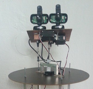
We used only 3 servo to achieve 3 degrees of freedom. The servos connected to the main axle with ball joints. And there is a drive shaft coupling near the upper two servos. It can't carry lots of weight, but the two camera works well with it.
In the future, we will reinforce this, because when we drive the robot with maximum speed this is a bit unstable
 BTom
BTom
Discussions
Become a Hackaday.io Member
Create an account to leave a comment. Already have an account? Log In.