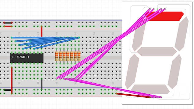
Controlling a 7 segment digit is usually done with a MAX7219 chip but they are geared towards common cathode displays. Digits and segments can be swapped to drive common anode type displays but this requires extra software and it probably can not sink the current & voltage needed for larger, multiple-led-per-segment displays.
The ULN2803 is a cheap and common 8-channel Darlington driver chip that can sink up to 500mA per pin at 50V. That's plenty of headroom to drive my digits so it's time to get out the breadboard.

The image above shows the Darlington IC wired up to the display segments. Output pin 1C controls segment A, pin 2C segment B etcetera. The digit common anode and COM are hooked up to +5V and GND to ground. Input pin 1B is held high here to light up segment A. Note the 7 current limiting resistors that will protect the segment leds from burning out.
Now i could wire inputs 1B to 7B to a digital pin on my Arduino but that would have two big disadvantages: it takes up 7 digital I/O pins and requires lots of digitalWrite() calls to switch on the segments needed for each digit. So I decided to shift the workload to a shift register.
Discussions
Become a Hackaday.io Member
Create an account to leave a comment. Already have an account? Log In.