Close
0%
0%

Small Home Automation System

A small and flexible system for building a home automation system.

Similar projects worth following
This is a small system to control some functions in your home. It can control the lights and the blinds and more. The communication between the different nodes uses a twisted pair wiring.

Today these nodes are ready or in development:
1) A switch module with up to four switches,
2) a relay module for two relays,
3) a power supply.

Project will no longer be continued.

The Protocol

The communication channel uses the same signal as the old EIB system. The data format is similar to EIB. You can find some more informations about the successor KNX here in this wikipedia article.

Why using wires and not RF?

Using wires have some advantages:

  1. No batteries required for the switches as all nodes are powered over the wiring,
  2. no interference with other RF systems

But has one disadvantage: It's necessary to have an additional wiring in the house electrics. The best way to build it in is during building or renewing phases.

In a later phase an interface with RF is planned.

The Modules

The Switch Module

This module provides four switches, which can send up to 16 different commands. The commands can be grouped, so that one switch can send e.g. three different commands.

The height of the module allow it to mount it directly on the wall.

The Relay Module

Containing two relays, this module can work as

  1. a switch for the lights or
  2. a relais for blind motors.

It has the cappabiltiy to react on up to 16 different commands. These can be split between the relays as needed.

The size of the module allow a mounting inside a flush socket, even below the switch module.

The Power Supply

As the data are modulated on the power supply voltage, a special power supply is needed. The nominal supply voltage for the system is 24V.

The power supply integrates also a configuration and programming tool.

  • 1 × Switch Unit 4channel switch unit for inputs.
  • 1 × Relay Unit 2channel output unit with relays for lights, blinds and others
  • 1 × Power Supply Power supply unit with programming unit

  • Mounting the Switch Module

    Siggi07/26/2016 at 19:36 0 comments

    Intro

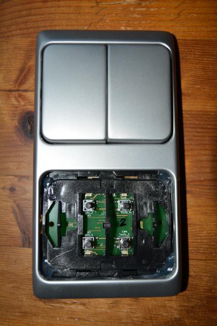
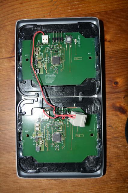
    One might be wondering, how the switch module can fit into a standard switch plate. In our house we are using a model which provide a mounting frame for it. Therefore it's easy to mount everything into this frame. The pictures shows how I have it done. It contains two switch modules with eight buttons.

    The boards and frames are fixed hot glue.

    The switch plates are a little modified on the back to fit it into the system.

    Front View

    Front view

    On the upper half shows a complete systems. On the lower half the switch plates are left for better look onto the frame. It can be seen that the switch plates are clipped into a frame.

    Back View

    Back view

    The back view shows how flat everything fits into the cover. It is possible to mount it directly onto the wall with a small hole for the bus wires.

    If there is a flush socket than it's possible to mount additional a relay module under the switch.

  • Test Setup

    Siggi06/25/2016 at 17:03 0 comments

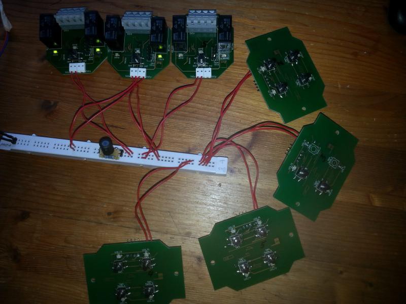
    Here is my test setup for programming. As the configurator is not ready yet, the setup for each node has to be hard coded.

    The three relay modules will be mounted in our bathroom, to control the lights and the fan. Additional two of the switch modules will also be mounted for the control of everything.

  • New Samples made

    Siggi06/13/2016 at 17:14 0 comments

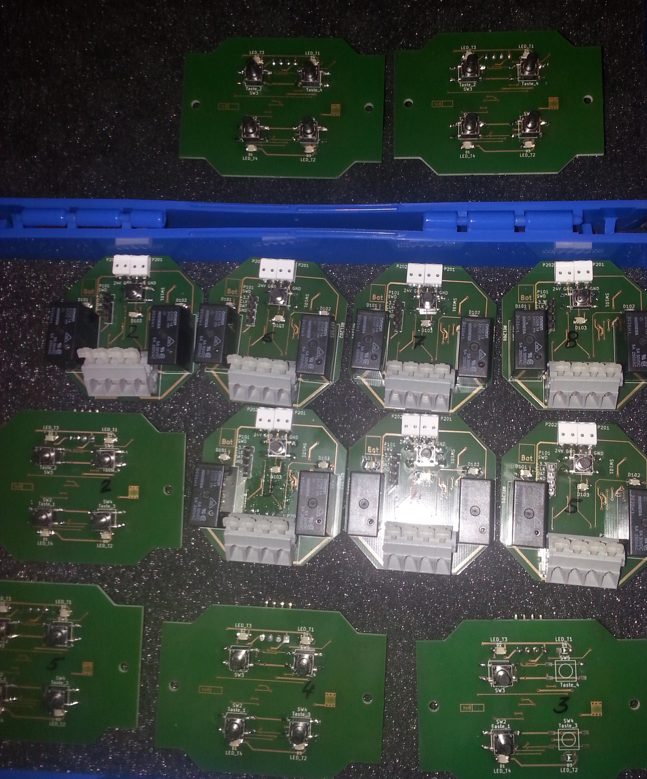
    The system at home still growing: Some more nodes ready to build in.

View all 3 project logs

Enjoy this project?

Share

Discussions

Similar Projects

Does this project spark your interest?

Become a member to follow this project and never miss any updates