-
Status 7/8/16
07/08/2016 at 21:01 • 0 commentsThe WEM is all mechanically functional (at least well enough for V1). The X/Y positioner is mounted with the bracket printed last night and I modified the Y slide (via hot air gun) to de-warp it and lay the slide flat on the table. I also was able to calibrate both axes to "good enough" accuracy (<0.1mm per 20mm movement), with both axes having the following settings:
X-axis: 53.202 steps/mm, 8x microstepping
Y-axis: 50.333 steps/mm, full step
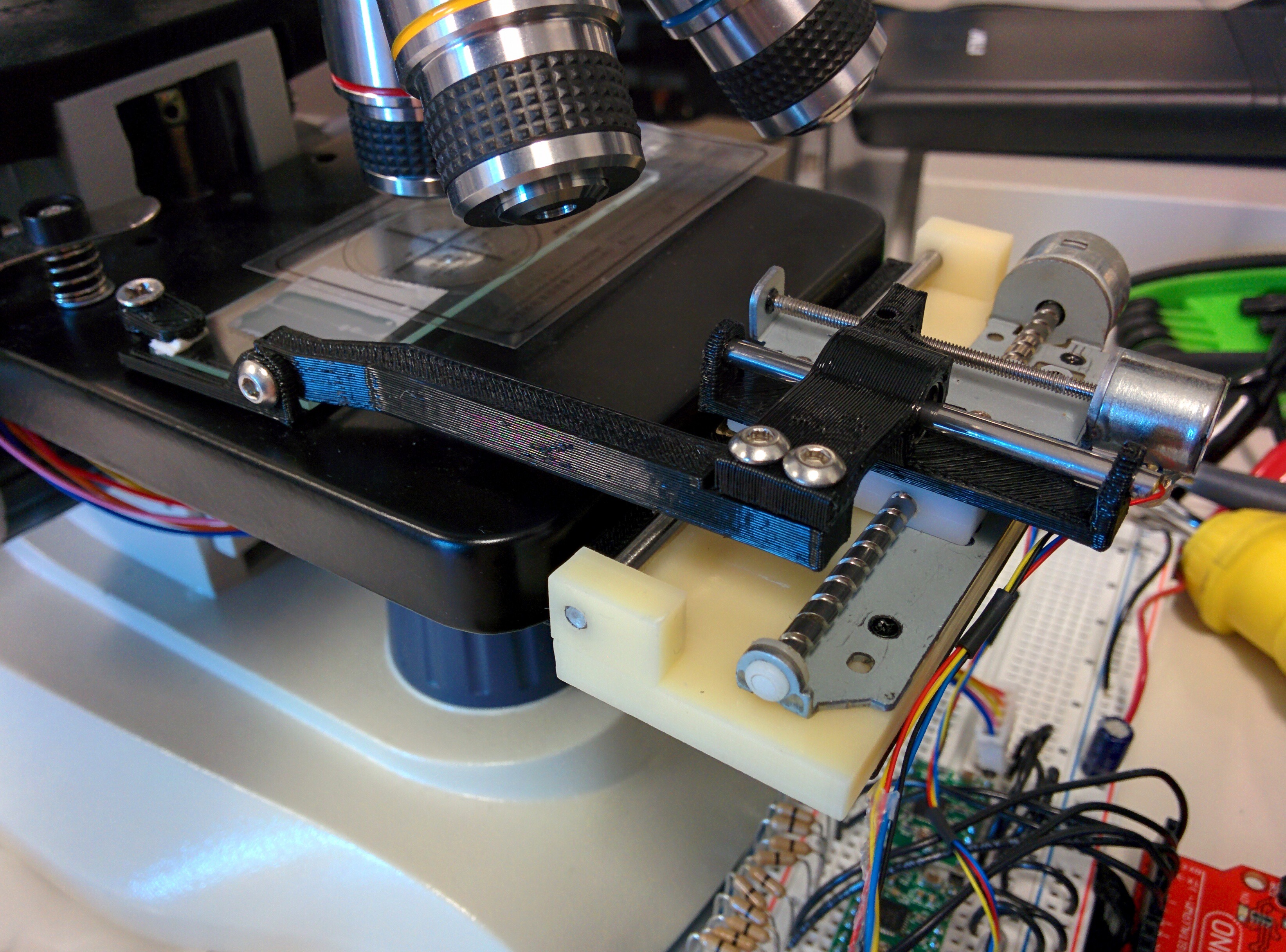
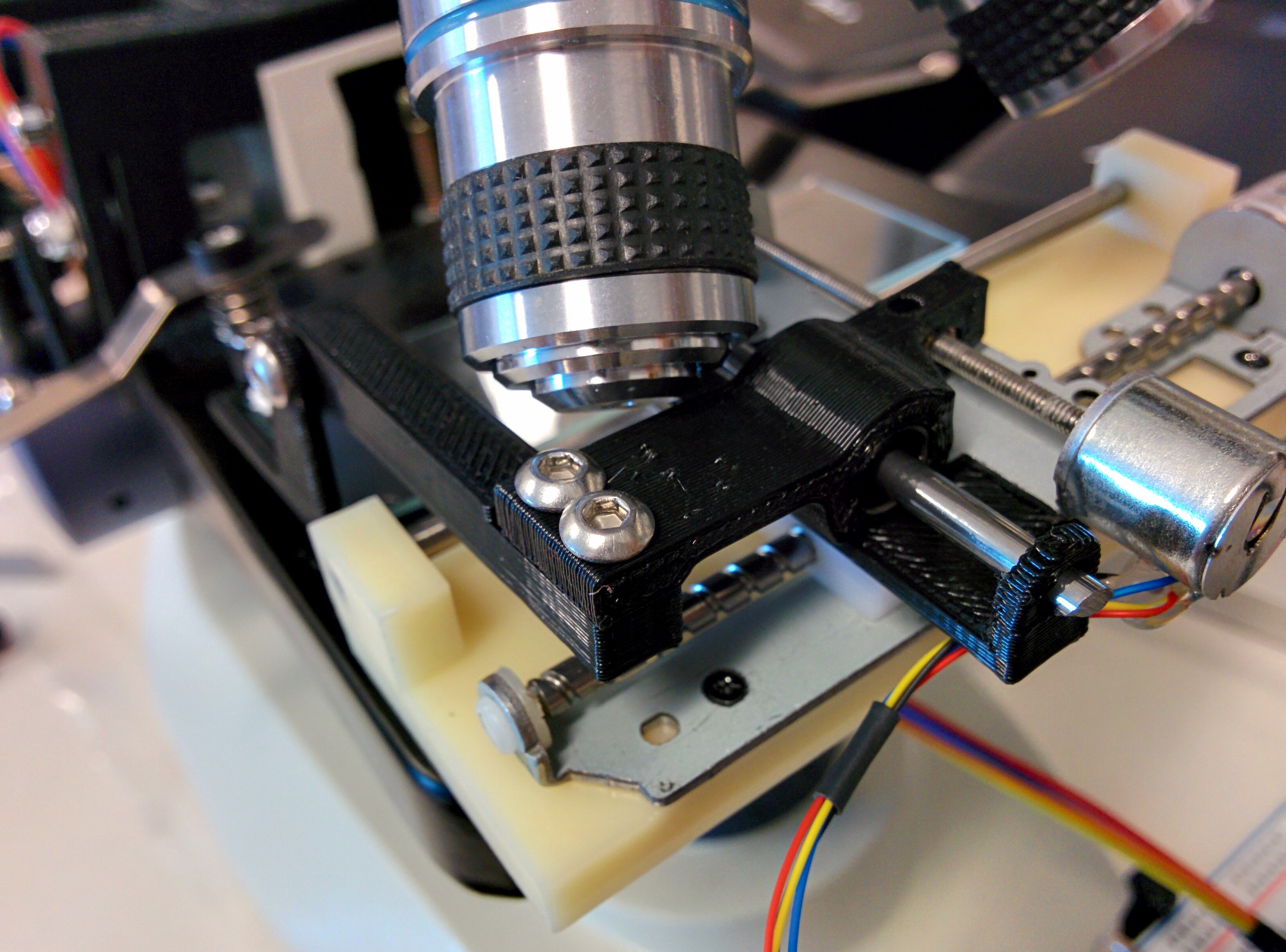
The Z-axis I'm leaving as is, since absolute distance doesn't have much bearing on it. Here's a photo of the final setup:
![]()
After calibrating both axes, I decided to give an "automated" panorama a shot using the phone's built in panorama feature. It didn't turn out so great, with some banding effects, and overall inaccuracy. I think I'll stick to moving the slide a fixed amount, stopping, taking a full size photo, then moving to the next position, and doing stitching as post-processing.
![]()
Here is a video compilation of the final state of the mechanical portion of the project:
-
Status 7/7/16
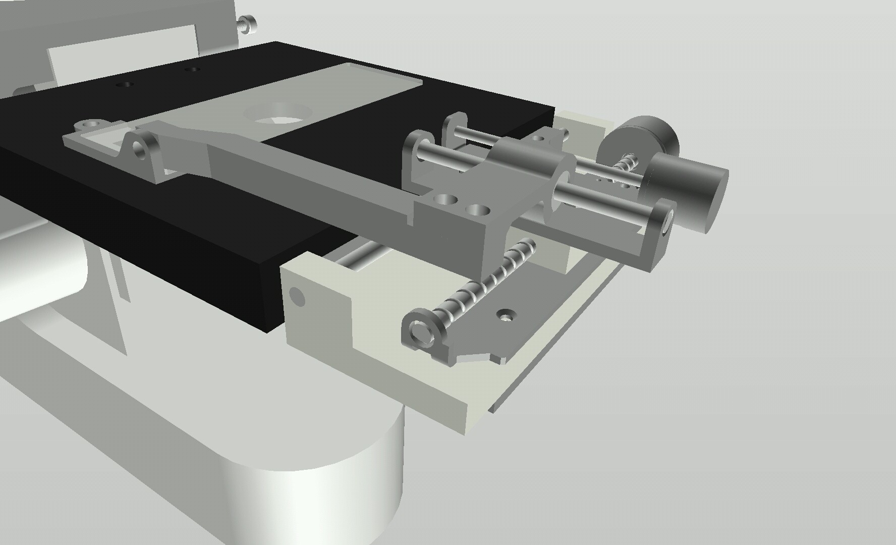
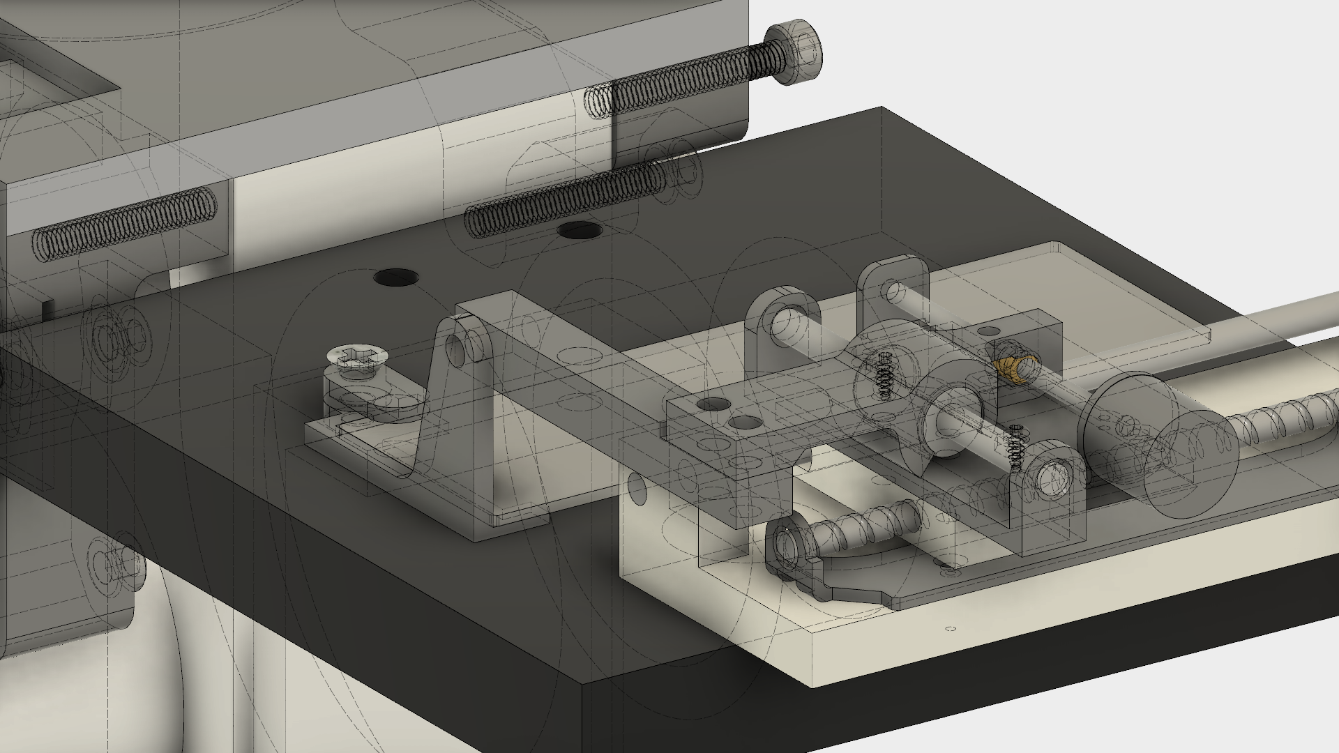
07/08/2016 at 04:49 • 0 commentsStill not having much time to work on the WEM this week but I've modified the X-Y stage a bit since it was running into the 100x objective. I've moved it down in the same plane as the sample platform instead of on top of it, which involved modifying 2 parts and making a third to hold the assembly.
![]()
The first 2 parts are already printed and assembled, just waiting on the holder which will be available tomorrow morning. I'll need to modify the long piece connecting the Y slide to the sample holder to compensate for the tilt of the Y slide.
-
Status 7/5/16
07/05/2016 at 15:12 • 0 commentsI finished modeling the new Y-axis parts to add a 3mm linear rail for stability.
![]()
I modified the Y-axis slide slightly from the picture above so it could be printed without supports, and also to solve a potential interference.
I printed the new parts and assembled it, two minor issues found, first inserting the LM3UU bearing caused the slide to bend slightly, and second the Y-axis motor was slightly too far away, so it can't be screwed down completely without binding. Here's a photo of the new parts assembled, unfortunately I didn't have time to test it out, but it seems the backlash is slightly improved, but still present due to the tolerances of the LM3UU and the X-axis slide (which might be slightly improved by adding an LM3UU to as well, but it is probably not worth the effort):
![]()
Another thing to note, the entire X-Y assembly is a bit too tall and interferes with the 100x objective, so I'll probably 3D print an adapter to mount it next to the focus plate instead of on top of it.
-
Status 6/29/16
06/30/2016 at 06:35 • 0 commentsI added the extra screws to clamp on the Y axis screw but there's still too much play, so I've ordered a pair of LM3UU linear bearings (same family as the LM8UUs commonly used in 3D printers) so I can add a rail for stability on the Y axis. I may modify the X axis slide to use a linear bearing also since I believe the rail is 3mm diameter.
-
Status 6/27/16
06/27/2016 at 22:43 • 0 commentsYou'd think I would have learned my lesson from the first major microscope model mess-up. Turns out I messed up the model again by not accounting for a protrusion from the top of the rectangular bit which prevents the motor mount as-is from working, and it's also 2.6mm thinner than I accounted for. Anyways I updated the model and modified the motor mount to accomodate, which was pretty simple, just needed to mirror the mount and add a cutout for the protrusion. Here's the model as it stands now:
![]()
I printed the new focus motor mount along with the X/Y parts, which needed a little modification to print nicely. I also ended up dremeling out some more clearance for the focus motor mount. Here's a short video of the three axes with 3D printed parts functioning:
There's still a lot of slop in the X/Y positioner but it's also missing 3 screws which should help with that. If it is still not resolved I may need to add another linear rail to help with stability.
-
Status 6/26/16
06/27/2016 at 04:43 • 0 commentsFinished modeling the two axis motors today and came up with a first pass at the motor to slide holder interface. It's not pretty but it should get the job done, assuming it isn't too much friction for the tiny Y-axis motor to handle. I'll print these 3 new parts along with the new focus motor mount Monday.
![]()
As far as electronics goes, currently I'm still using an Arduino running Grbl controlled directly by a PC (using serial terminal). Next step once I get everything working mechanically is to figure out the X/Y/Z steps/mm and speed/acceleration parameters to lock down in Grbl, then interface the Arduino with an ESP8266 running a basic web server for control.
-
Status 6/24/16
06/25/2016 at 05:59 • 0 commentsHad a lot of work this week so not much time to work on the WEM, but I had a little time today to re-model the Z-stepper holder after my model blunder last weekend. Here's the new design, which will be printed Monday:
![]()
Same basic mechanics as the old version, just moved up above the focus knob instead of below. I'll be able to eliminate the clamp (which probably wouldn't have worked too well anyways) and just use 5 screws (2 on the motor side, 3 on the opposite side) to fix the holder against the microscope.
-
Status 6/20/16
06/21/2016 at 03:33 • 0 commentsWell that is embarrassing, I made a huge error on the positioning of the focus knobs of the microscope so the models I made yesterday are invalid. PSA: Measure twice! Or at least take a look at the model and see if it makes sense!
I did print the bracket anyhow to see whether the concept works, which it does:
Will measure the force needed to engage the wheel in order to select the right size extension spring, and of course heavily modify the stepper motor mount in order to work with the microscope.
-
Status 6/19/16
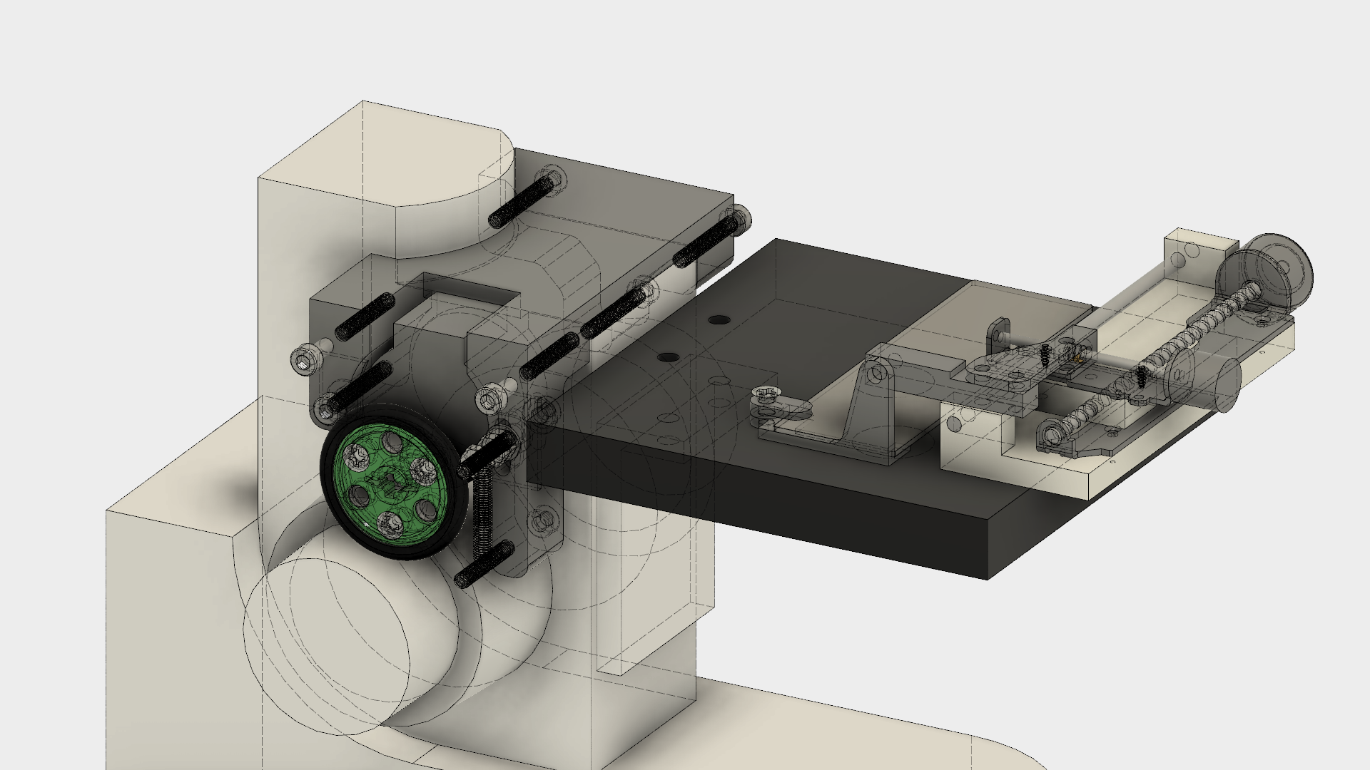
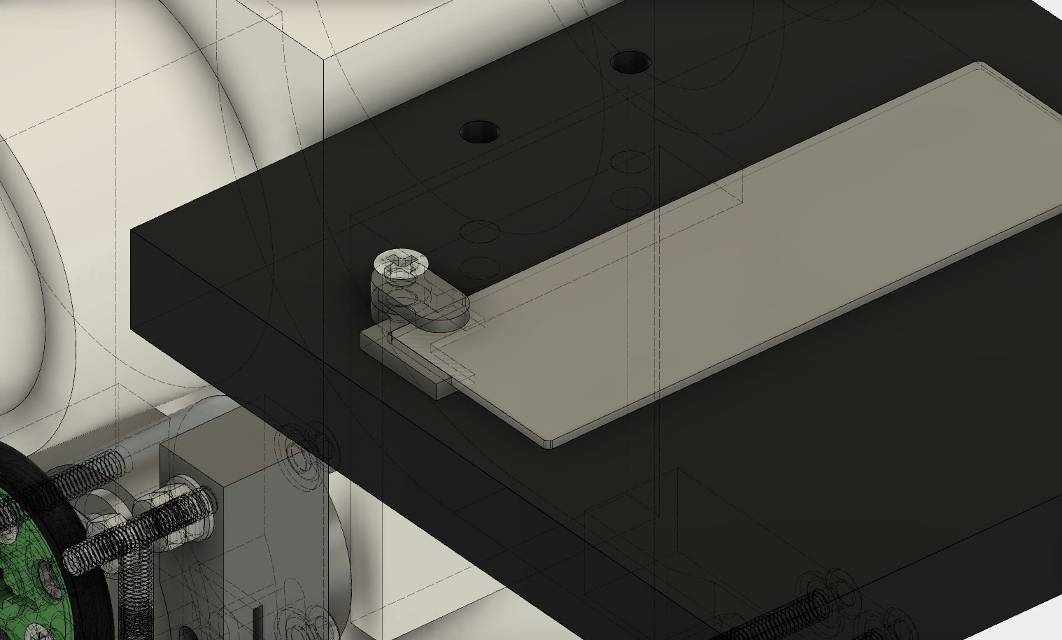
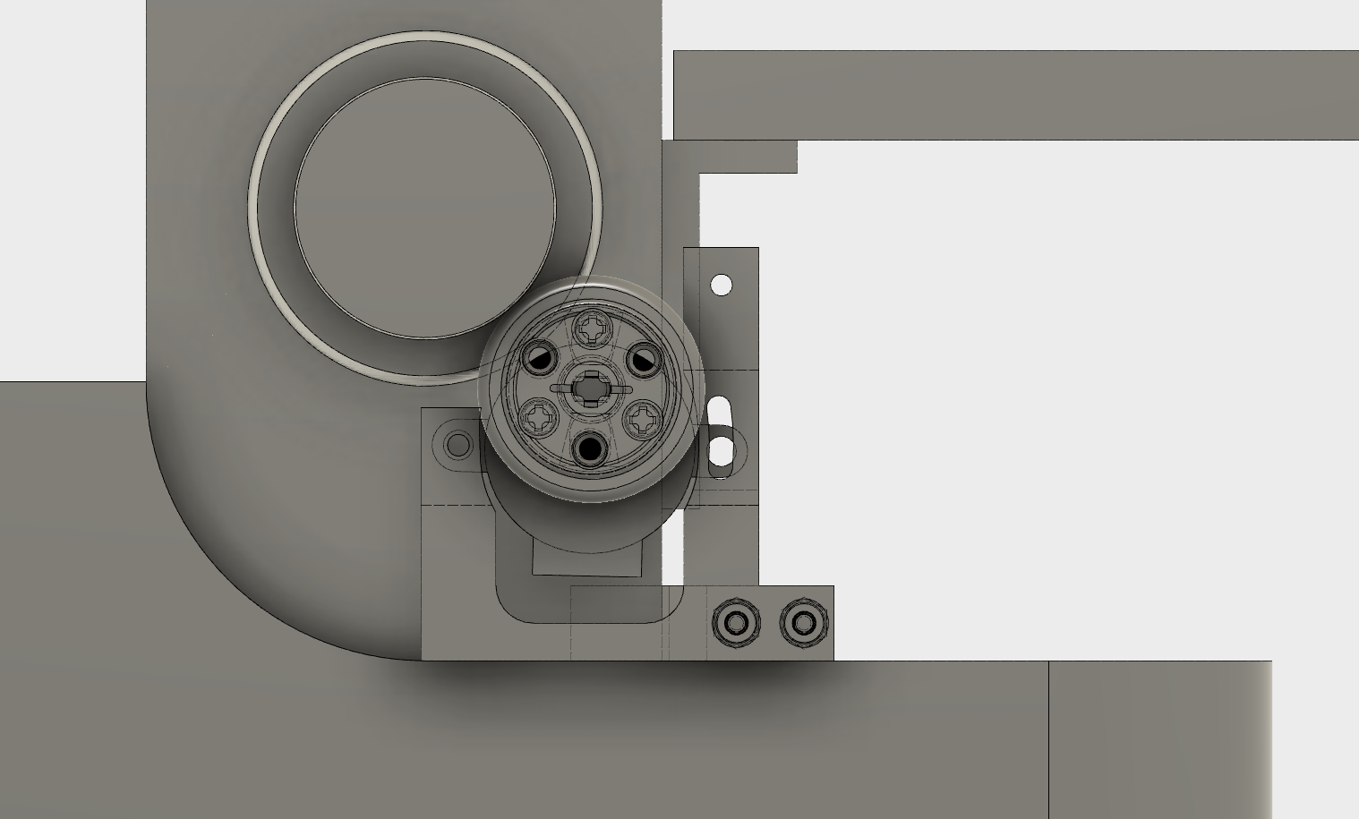
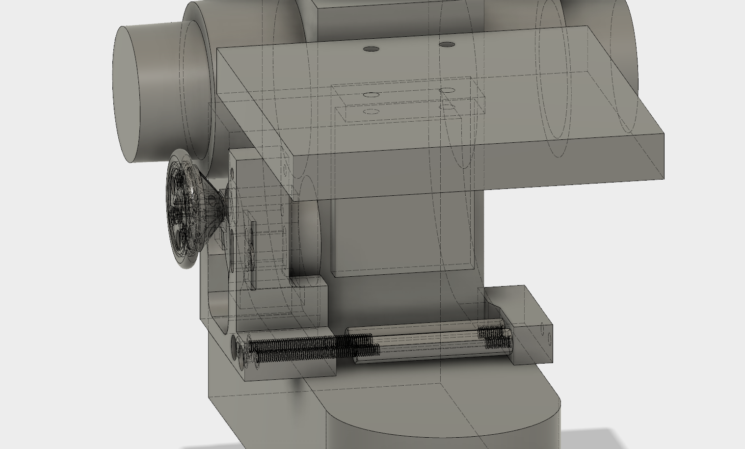
06/20/2016 at 01:50 • 0 commentsNo real update for today. Got the tires for the Lego wheels and updated the model slightly to reflect real measurements. Also added all hardware to the model to better show how the mechanism will operate:
![]()
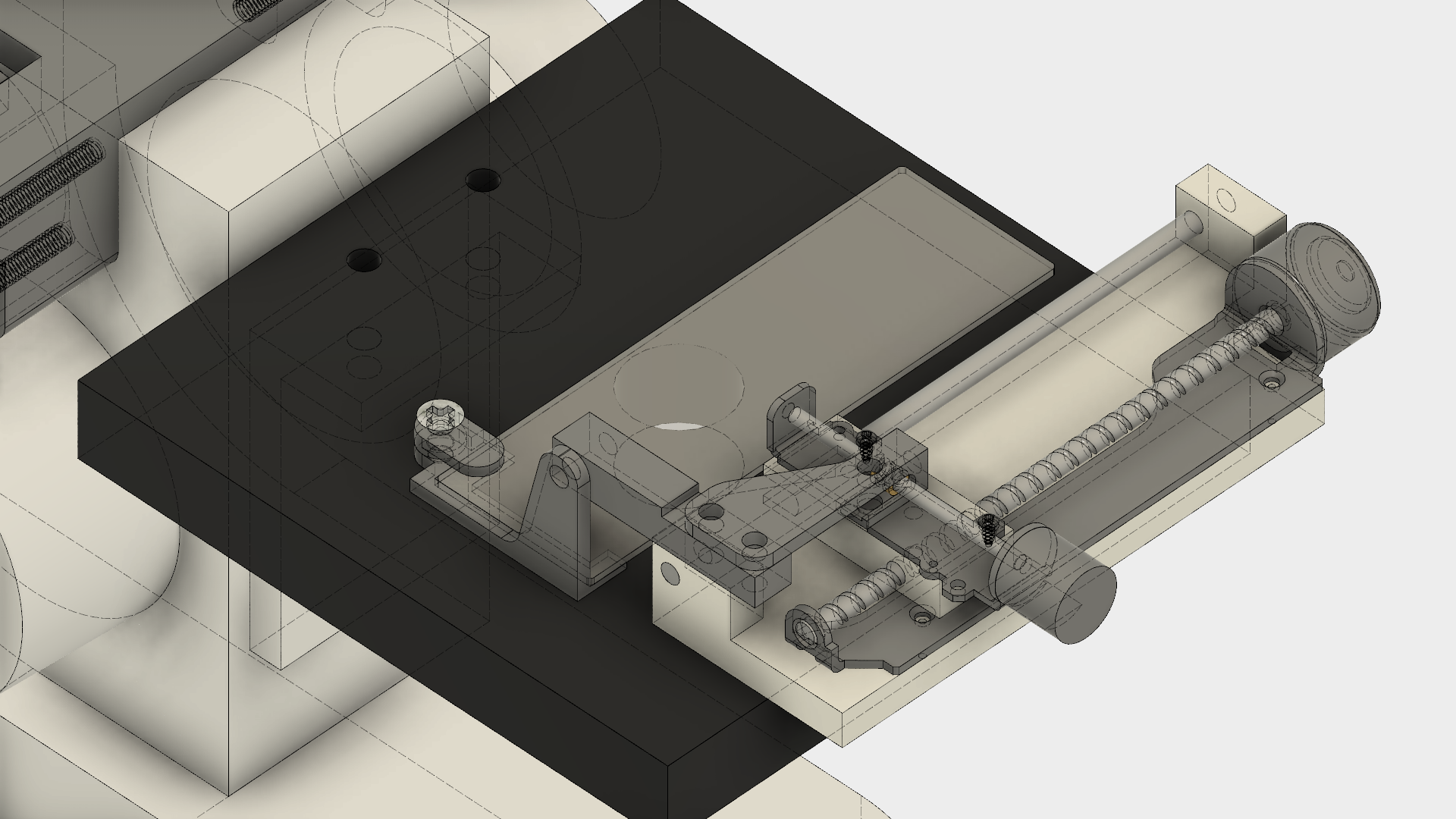
Started modeling the holder for the slide, I think just a corner with a sliding clamp (will have a small rubber foot on the clamp to put pressure on the slide) will do. Hopefully the tiny Y-axis motor can overcome the friction of the assembly on the microscope's table.
![]()
-
Status 6/18/16
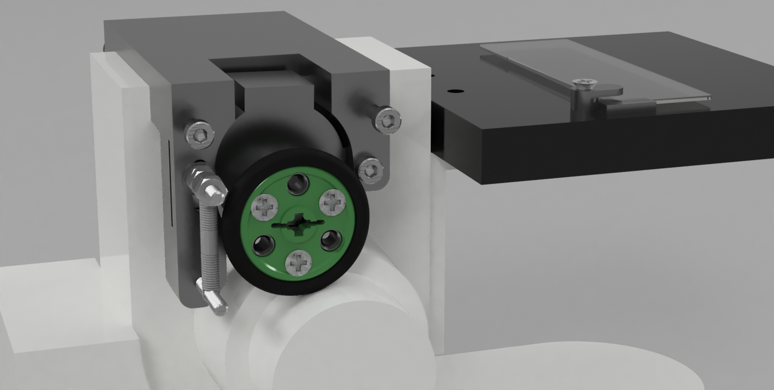
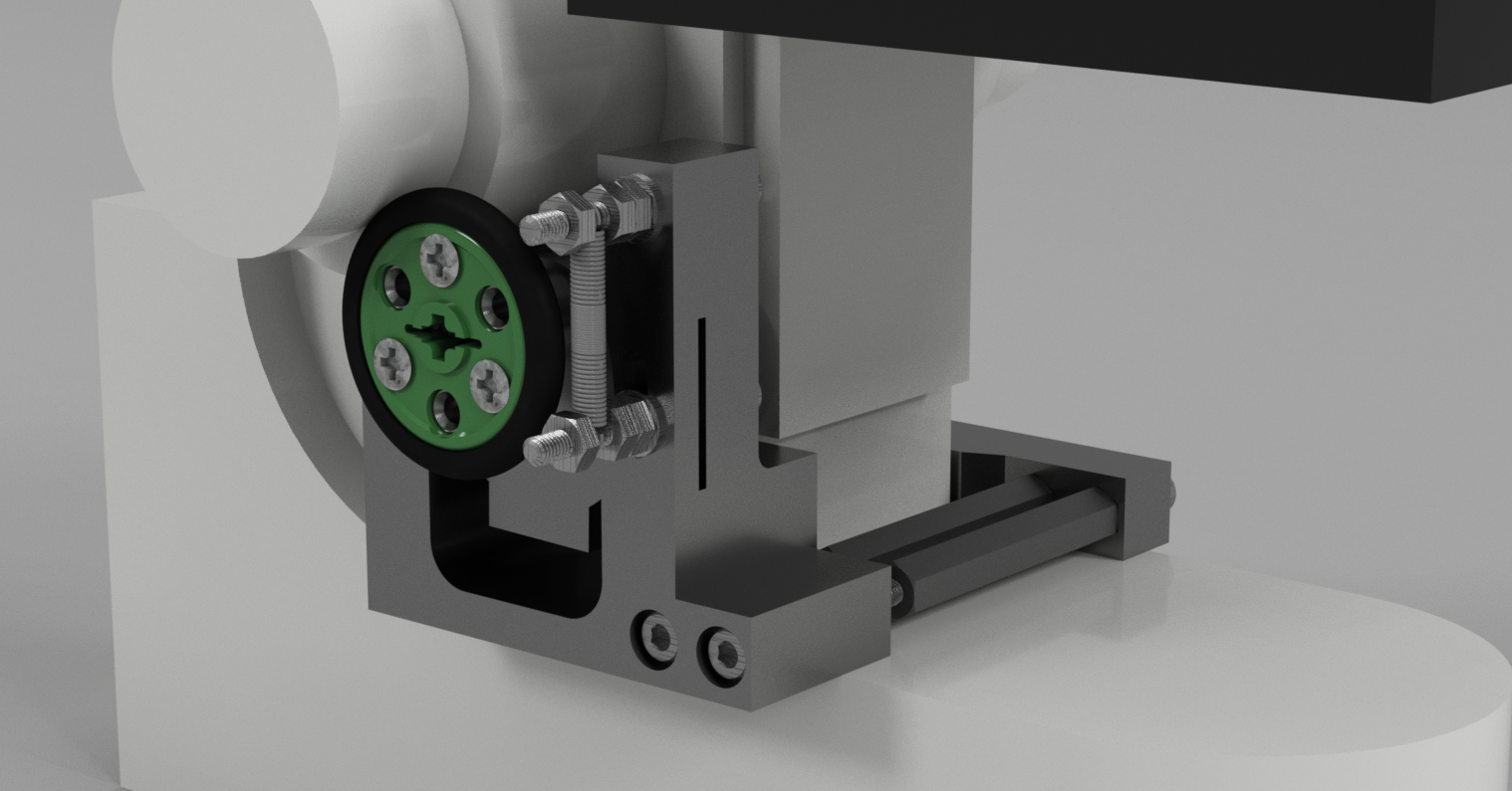
06/19/2016 at 00:04 • 0 commentsStarted modeling the 3D printed focus motor holder in Fusion 360. The plan is to have one side of the motor on a pivot, and the other side with a tension spring pulling up on it and keeping it in contact with the focus wheel. Ideally the force would be enough to give good traction between the motor and wheel, but allow for manual movement, or simply allow for a latch to keep the motor out of contact with the focus wheel. I've designed this holder with a clamp to hold it in place on the microscope, but if that doesn't work I may need to drill/tap into the microscope to hard-mount it.
![]()
![]()
I plan to use M3 hardware (2x M3x30mm socket cap bolts, 2x M3x15mm screws, 3x M3x20 screws, M3 washers, 2x M3x40 threaded hex spacer) to assemble the motor and holder/clamp. I'll purchase the missing components like the threaded spacer from McMaster or eBay, though I have plenty of M3 screws to hold me over for now.
Web Enabled Microscope
Enhance a microscope with web control, enabling gigapixel panoramic or focus stacked shots, live streaming/control and more!
