Lee Djavaherian
-
Released Source Code Today
06/02/2018 at 05:21 • 0 commentsOk, the first version of the source code for TrillSat was released a couple of hours ago under GPL 3.0, and a copy of the source tarball was uploaded to the Files section of this project. It includes the most important files, the OpenSCAD program that generates the STL files for 3D-printing (and animation), the electrical schematic, the C source files for the two ATtiny 1634 microcontrollers, the Lua source for the Huzzah ESP8266 running NodeMCU, and the Python 2/3 and BASH sources for the Raspberry Pi Zero W. The README file also details several smaller changes that need to be made to various configuration files.
The tarball doesn't contain the entire project, only the core craft design files, so I didn't include the 100+ pages of technical information which are available on my TrillSat home page at http://greatfractal.com/TrillSat.html, since I wanted to keep the tarball small. I also left out the STL and G-code files that I used to print the parts, since they consumed several megabytes (and are easy to generate using my OpenSCAD program and Slic3r), and I left out the KiCad source and library files as I only use it for the visual schematic and don't use any of its other features.
The "Three-Tridant Orbital Mechanic" PWM drive system is now working, but it is very crude at this stage. I created a new "Park" command which drives the Planetary Mass at different acceleration/deceleration values and speeds as it passes the Hall-effect switches, automatically switching between Sign-Magnitude and Lock-Antiphase on-the-fly to re-park the mass at sunrise position during the night (and lifting the entire weight of the craft). It works in testing on a table, but I have not yet tested this system on the tether (and I will probably need to tweak the values to match different friction/torque requirements).
I had to match the speeds of Sign-Magnitude and Lock-Antiphase to ensure smooth hand-offs, since Lock-Antiphase runs at twice the frequency of Sign-Magnitude, so I sped up Sign-Magnitude to compensate, rather than slow Lock-Antiphase down. Lock-Antiphase has half the resolution, so slowing it down won't allow a perfect match with Sign-Magnitude during a non-linear acceleration, but Sign-Magnitude can have its resolution cut in half to match, which preserves the congruence.
I also had some spontaneous ATtiny reboots during testing, since I moved my bypass capacitor too far away from the ATtiny after I replaced the last BLDC, and the supply voltage dropped below my brown-out detection threshold of 4.3 volts, so I lowered it to 2.7 volts which helped until I can get around to fixing the problem.
The code is crude at this stage, but hopefully it will give others insight into solutions for several problems that I had to overcome: how to take control over the UV-5RA flash memory and minimize writes to the flash using 16-byte blocks (something Chirp wasn't designed to do), how to create a crude XMPP server on a memory-constrained ESP8266 running NodeMCU, how to program a PBBS using AX.25 Unix programming techniques instead of the C library, how to craft the APRS message, and how to wrangle a custom radio interface using a Virtual UART and Virtual PTT line.
It also shows the various ways to control the two very different types of motors under PWM (brushed and brushless) using a single microcontroller, maxing out both of its hardware timers and creatively using interrupts. And of course, there are a lot of different types of IPC, job processing, multiprocessing and concurrency going on with 4 CPUs that interoperate.
It is a fascinating experience for me, and I hope you find some of it useful.
-
Source Code Cleanup
05/21/2018 at 06:12 • 0 commentsI've been cleaning up my various source code files and getting them ready for release in the next couple of weeks.
I edited my OpenSCAD source to allow variables at the top of the code to change the output (to render individual parts for printing, display the entire assembly, display the exploded assembly, and perform an animation). In my C, Lua, Python, and BASH code, I also made a pass through my config files to section out my private code, removed hard-coded values, and renamed some directories to more appropriate names.
It takes time to think up appropriate names while programming (and pulls you out of your context), and this can break your concentration when you are involved in something complex.
My paper notes are the same. I have good spelling, penmanship, and drawing skills, but you'd never know that by looking through my technical notes, which are almost indecipherable, since I scribble train-of-consciousness as fast as I can think, and similarly, this doesn't allow me to access my spelling or fine motor skills, since I'm not focusing on them at the moment. It really isn't writing or illustrating--it's a brainstorm data-dump: misspelled words and scribbly ideograms. I then make a second pass over the material if I need to formulate a visual or literary language. But it's kind of depressing looking at hundreds of pages of your own old, messy notes...
My source code is the same way. First I get it working (using whatever constructs are needed), then I make a second pass to refactor into more modular programming practices, abstracting away similarities, eliminating redundancies, etc. But this takes time. As proof-of-concept, my first release, Version 1.0, is always messy. I don't use alpha/beta indicators or 0.xxx versioning to signify versioning, as every release is a beta as far as I'm concerned. I just do the major.minor thing and start with 1 and then use the decimal values in sequence to denote future versions, only changing to a 2 if there is a significant improvement (which has never occurred to date).
When I was young, I was a perfectionist, and it was easy for others to see this in my work, but as I got older, I realized that I wasn't optimizing the "entire" structure, and so I began to apply my perfectionism to systemic and systematic processes and not visual ones, and this is sometimes hard for anyone but myself to recognize (an ugly shell with beauty inside, so to speak). But the fact that someone like Leonardo da Vinci can draw and write beautifully in his notebooks while also expressing complex, abstract concepts (beauty throughout) is astounding, and I wonder how he achieved this ability (or perhaps it wasn't really what I think it is, I don't know).
In some ways, though, when you force yourself to slow down and perfect something trivial, like the simple notes, the illustrations, the prose etc, it helps to clear the mind when you look back at that thing later, and may actually be a better way of doing things (more gains in the long run) than my messy "molding over several iterations" approach; I don't know, since I've never really tried it for anything sufficiently complex. But it would take a person of the utmost skill to do such things.
Several years ago, I created a BASH script which adds the appropriate GPL license files, extracts README documentation from my website, adds the version number, strips out my private code segments, packages everything into a tarball, and stores the released versions in an archive. This allows me to program and test my code in place with all of my hard-coded customizations, and then I can just run the packager to generate the correct tarball for public release.
But with the TrillSat project, I've encountered a situation that I haven't dealt with before: this is my first "open-hardware" project containing an electrical schematic, 3D-printed parts, and source code for several different CPUs, all of which I am trying to publish. In other words, there are electrical, mechanical, and software designs, all combined into one project, which means that the packaging separation and selection of appropriate open-source licenses have to be carefully considered.
I also had to modify my packager to account for C and Lua files which use a different form of commenting than typical Perl/Python/BASH style # comments. For example, C99 and above can use // and Lua uses --. Since I use the comments sections to add control codes, my packager needs to parse them, and the license headers also need to be inserted into those comments, appropriately, for that language and type of license.
And I discovered a new problem that bummed me out: when I upgraded my smartphone to Android 6.0 (AOSP) a while back, it broke the Access Point functionality of my ESP8266 NodeMCU code, which was working fine before, since this version of Android does not seem to connect to an AP without a real DNS server (but of course, I don't use one since I'm using it for the TCP/IP protocol only, not the Internet). I'm not sure how I will handle this yet as I don't want to downgrade my phone OS, and building a DNS server in NodeMCU is not feasible. Somehow, I'll need to spoof the client to convince it that a real DNS server is present.
And, lastly, I still have to re-test all of my code to ensure that it still works after I've stripped out those customizations, which is tedious. There is a lot of work to do over the next couple of weeks...
-
BLDC/Gyrofan Is Back in Action
05/08/2018 at 11:01 • 0 commentsI fully charged the two Lithium-ion battery banks (around 8.4 volts in series), but the BLDC problem that I mentioned in my previous log entry still occurred, so I wrote up a small amount of Python and C code to create a new XMPP command called "bldctest [testnumber]" so that I could activate the coils in different polarities for 2-second periods to troubleshoot. Testnumber 1 is +U -V, 11 is -U +V, 2 is +U -W, 22 is -U +W, 3 is +V -W, and 33 is -V +W.
I was then able to connect my multimeter to read the voltages at BLDC coil terminals U, V, and W and text the appropriate command to see what was going on. It was soon apparent that the U coil wasn't working, and it was indeed only running on only 2 phases, as I surmised. I tracked it down to a bad solder joint on the U coil L6234 enable pin (EN1 in this case) that was only receiving .5 volts instead of the full 5-volt logic coming out of the ATtiny 1634 (which I have running at 5 volts), which was too low to activate the L6234 logic gates/MOSFETs. So I reheated the joint to correct the issue, and the Gyrofan is once again operational. Thankfully, there doesn't appear to be any damage to the L6234 or the ATtiny...
Whew!
To ensure that this chip lock-up issue doesn't occur under intermittent solar power and burn out the motor again, I turned on brown-out detection on both ATtiny 1634's and set the threshold to 4.3 volts. If the voltage drops below 4.3 volts (or 4.1 volts minimum) the chip will go into reset mode until the voltage is restored. These ATtinys can operate at lower voltages, but since they should only be receiving power from my solar charger's 5v USB output (or via a 5v USB bypass line in test mode), I set the threshold fairly high. This ensures that the solar charger output has at least ramped up to operating voltage and should be more stable. If the high-current motor PWM drops this voltage below the threshold and resets the chips, I may try lowering it to 2.7 volts, but I'm hoping that my bypass capacitors will handle it and this won't be necessary.
First, I set the High Fuse Byte to DC (11011100) to enable a BOD trigger level of 4.3 volts (typical):
sudo avrdude -pt1634 -c linuxgpio -U hfuse:w:0xDC:m -C avrdude-sawyer.conf
sudo avrdude -pt1634 -c linuxgpio -U hfuse:w:0xDC:m -C avrdude-huckleberry.conf
Next, I set the Extended Fuse Byte to F5 (11110101) to enable Active, Idle, and Sleep Mode Brown Out Detection:sudo avrdude -pt1634 -c linuxgpio -U efuse:w:0xF5:m -C avrdude-sawyer.conf sudo avrdude -pt1634 -c linuxgpio -U efuse:w:0xF5:m -C avrdude-huckleberry.confSince both AVRs, Sawyer and Huckleberry, share the same SPI programming lines except for their reset lines, I use two custom avrdude.conf files to program each chip, with only their reset lines differing between the files.
Also note that there are two bugs in the latest released 6.3 version of AVRDUDE that have to be fixed before it will correctly program the ATtiny 1634:
http://savannah.nongnu.org/bugs/?40144
http://savannah.nongnu.org/bugs/?47550And AVRDUDE has to be compiled with the --enable-linuxgpio=yes option for bitbang support. I use Arch Linux, so I just use the Arch Build System to make the corrections in the source and then recompile (and then I also edit the avrdude.conf file to add the other bug fix to the ATtiny1634 section).
All TRILLSAT-1 hardware is now operational again.
-
Second BLDC is Installed (and giving me trouble, of course)
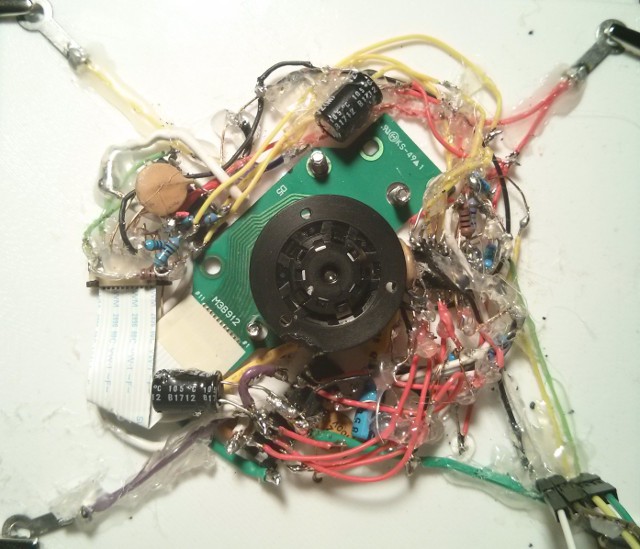
05/07/2018 at 06:09 • 0 commentsThe replacement BLDC has been soldered in place on Circuit Board C, and the new ZIF ribbon cable connector seems to work pretty well. However, since I'm trying not to wire on top of the BLDC this time, I've just about run out of room for the circuit underneath the Gyrofan wheel. Dang.
The ZIF connector has about 1 mm clearance, and the larger 100 uF electrolytic bypass capacitors wouldn't fit, so I had to overlap the one for the L6234 over the BLDC board (which can be bent out of the way), and I had to move the one for the ATtiny 1634 several centimeters away, so it won't work as well as it did before.
![]()
This BLDC is giving me trouble, however. It has a different sound when it runs, stalls on slow-starts, and doesn't have as much torque as the first motor (it acts as if it is running on only two phases). The motor wiring is not the cause since I've tried every combination of hall-effect sensors and coil patterns in software to rule out a motor miswiring on my part, and the 3 hall-effect sensors are being properly detected.
So I've narrowed it down to motor drive current: it is either the L6234 circuit (perhaps the charge pump), the L6234 itself, or the ATtiny ports/wires driving the L6234. I'm really hoping that when the first motor burned out that it didn't do a full short and also burn out part of the L6234. And the ATtiny ports can also burn out if the L6234 loses its 7.4 volt supply voltage... I really hope this isn't the case.
There is another possibility that I didn't consider, though. As I've been testing the motors indoors, I've been draining the Lithium-ion batteries, and they are now around 3.5 volts each. In series, this equates to 7 volts, the minimum operating voltage of the L6234. Perhaps it is not operating efficiently enough.
So I opened up the Power Regulation box and soldered a wire to the 5v power input of the Lithium-ion charger board, which is supplied by the solar charger, and exposed this wire outside of the box in one of the wire channels between the Circuit Boxes and Battery Frame. This allows me to access the wire to bypass the solar panel in cases where I need to charge the Lithium-ion batteries during testing. There is no way to charge them when the case is closed up unless I have sunlight. Now all I have to do is open up one of the wire channel access panels.
I'll test again once they are fully charged to rule out any issues with the supply voltage.
I decided to solder the bypass wire after the solar charger MOSFET thinking that, as long as the MOSFET was off, the current wouldn't feed back into the charger--but I forgot about the MOSFET body diode, and so it fed back anyway, lighting up the solar charger LED. I'm hoping that the output stages of the solar charger's step-down converter include their own diode and this won't be a problem. I'm not going to actually use the solar panel while charging the batteries over this bypass wire, and the voltages are the same, so I'm probably okay.
So, if the battery voltage is not the problem, I will have to write some software code to pulse the coils in different patterns so that I can test them with the multimeter (but short enough durations as to not overheat the coil). The most likely cause is that, when moving the wires out of the way to make room for the new motor, I probably agitated the wiring and created a bad connection somewhere, as my solder joints are fragile.
And I also almost had a heart attack when, to my horror, I accidentally melted the plastic rotor mount of the pristine BLDC when I was soldering... *sigh* ...but what can you do. Luckily, it still fits within the Gyrofan mount, and the loss of mass was negligible.
Please excuse the horrible circuit appearance of Circuit Board C--the hot glue makes it look worse than it really is. I try to only apply hot glue to the areas that are mechanically the weakest, and I purposely leave many solder joints exposed in case I need to repair or modify it in the future.
Hot glue is actually a really neat medium to work with, in conjunction with the PETG thermoplastic, as it is one of the few things to stick to it, and it can even be shaped for some mechanical functions. It can be easily removed with pliers, hobby knife, fingernails (or by reheating it to free stuck wires). The wires look haphazard because I've had to remove and replace components a few times--the initial circuit was actually quite clean.
I literally used a 30-year old blunt-tip soldering iron to solder 90% of TRILLSAT's circuits, since I cannot find new tips for it that match the screw threads. I filed down the copper tip in the beginning of this project, but this removed the protective layer (iron, I assume) causing the tip to dissolve.
Since one of the tiny wires to the ATtiny 1634 (an SOIC-20 package) broke free when I was installing the new BLDC, I had to create a makeshift tip just to fix it without wrecking the circuit--so I wrapped a copper wire around the iron and sharpened the wire (then used my magnifying lamp to see).
![]()
It's crude and messy, but it's all I have. Blunt-tip soldering is a lost art, I tell you.
-
BLDC Replacement and Failure Analysis
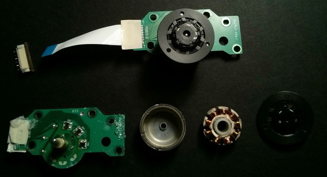
04/23/2018 at 03:51 • 0 commentsI purchased an old, used Lite-On LDW-411S DVD+-RW drive (manufactured in 2003) that someone was selling on eBay and removed the BLDC motor to replace the one that I burned out a few weeks ago due to the chip lock-up/stall issue mentioned in my earlier log entry. One of the problems of re-purposing old parts, however, is that drop-in replacements are harder to find (but I never expected to burn out my first one!). Holes have been drilled for Gyrofan mounting, and small nuts have been epoxied behind the holes for easy assembly to the Gyrofan wheel. I also had to be careful to ensure that the metal shavings from one of the holes that I drilled in the metal board (to widen it) didn't enter the motor, so I taped up the motor before drilling the holes.
This time around, though, I decided to de-solder the ZIF ribbon-cable connector from the drive's circuit board and will use this, in place of direct soldering, to more easily and quickly disconnect or replace the motor in the future.
![]()
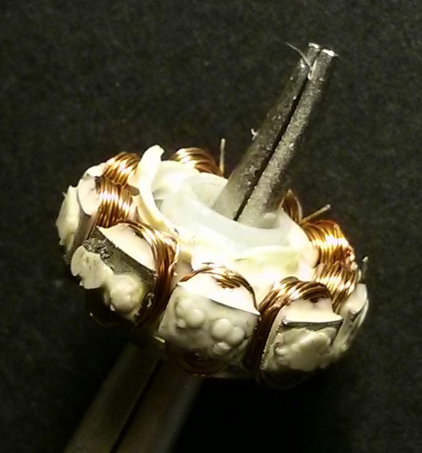
I tend to avoid analysis, deferring to logical deduction, but this was a good opportunity to see exactly what kind of motor I am dealing with, as there are many different types of BLDCs. As you can see, it has 9 stator coils and the heat melted the plastic around the coils, wedging it against the magnetic rotor.
![]()
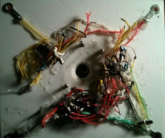
I had to clear out a lot of the wiring on Circuit Board C to remove the old BLDC and will be more careful next time to wire around the BLDC to prevent its removal from being obstructed. The heat from stalling out the old motor actually caused the black printing to melt onto the white PETG gondola backplane.
![]()
Once the new BLDC is in place, I plan to get some video of both of the motors (the BLDC and the brushed DC screwdriver motor) under PWM control. Then I'll start a pass through my Python, C, Lua, and OpenSCAD source code to get a version ready for open-source release. Currently, my code has a lot of hard-coded customizations which first need to be generalized. -
Took it outside today
04/08/2018 at 00:49 • 0 commentsIt was a sunny day today (but a little cold), so I went outside and took a photo of TRILLSAT-1 tied to a tree and decided to make it the main photo for this project.
-
Current Status and Testing
04/07/2018 at 06:40 • 0 commentsCurrent Status
I've spent about one year programming the core systems, and one year building, and it is now in the final stages of writing/perfecting the highest level algorithms and adjusting for real-world use. The packet radio interface has been tested on-the-air and does work. The PBBS system and APRS beacon has been tested in simulation (and works), but hasn't yet been tested over-the-air. The TROT drive system has been tested on the indoor test frame, not in use outside on actual trees or weather conditions yet, but much of it is still under manual control. The full size 2m/70cm antenna is only theoretical at this point but is simple to build, something I have left to the very end, but I will need to add an appropriate female SMA bulkhead adapter to extend the 50 ohm terminal outside the Radio Box. The THUMP system is only about 50% completed, as the SIMTHEO algorithm does work, but inverting it and adapting it to the tethered accelerometer interrupt is mainly theoretical at the time of this writing.
All electromechanical systems are functioning, and I have created a large set of XMPP commands to manually control the craft and read its sensors, but there are only a few autonomous robotics systems in place at the time of this writing.
Working autonomous robotic systems
- Solar Charge Mode: The power regulation microcontroller (Huckleberry) can automatically monitor the voltages of the craft's battery banks and switch the craft's systems from one to another to charge one bank while using another.
- Orbital Mechanics: The Planetary Mass can slow start and park at different positions corresponding to sunrise, solar noon, and sunset.
- Gyrofan: The gyro can perform slow starts and hold itself at a specified RPM, using 3 Hall-effect sensors in conjunction with a quad comparator, increasing energy to hold its position by varying PWM and/or switching to different drive modes. Although, due to a freak coincidence (explained later) the gyro BLDC motor windings overheated to the point where the motor has seized up and I have ordered a replacement, but have not yet soldered it in place.
- Pitch and Roll angle--The system can compute the Pitch and Roll angles to within around .1 degree by calculating its angle with respect to gravity.
Autonomous robotic systems that still need to be implemented
- The system can solar charge itself, as mentioned above, and the CdS cells can read light levels, but I haven't yet applied Lambert's cosine law to estimate the angle of the sun and have the unit automatically set itself to that angle. I still need to line the LDR Tubes with an opaque material to prevent light leakage through the translucent PETG plastic. This angle should be used by the Motor Control ATtiny (Sawyer) to reposition itself automatically, incorporating its internal timer.
- The Pi needs to use the accelerometer data to increase the precision of the solar angle set by Sawyer. If the Pi goes down, Sawyer can act independently.
- I have not added active pendulum stabilization algorithms via the planetary mass or the gyroscopic reaction wheel (this is a luxury item that can wait until later).
Sign-Magnitude and Locked-Antiphase PWM are working, but the Planetary Mass orbit still needs to automatically switch between modes depending on the point in the orbit.
Results of testing so far:
Negative
- The Gyrofan clearance is too tight in the fan duct and Circuit Board C. The wiring channels are too narrow. This makes it hard to assemble.
- The Gyrofan is ineffective at the speeds that I have tested. I have not fully loaded the gyro mass, but I don't want to add any more, as it decreases the max solar panel tilt angle (which is already borderline). But I am afraid to run it at faster speeds at this point (I don't want it to disintegrate and damage Circuit Board C). Once the other algorithms on the craft are added and documented, I may try ramping up the speeds to see if I can get appreciable stabilization from the gyro.
- The weight is the primary issue, period, being at 8.28 lbs (3.76 kg) If the craft was lighter, it would have higher elevation and the gyro would be more effective. The tether axis (Y-axis) needs to be offset to correct a multiplicative feedback effect that is occurring with the gyro. The weight also makes the craft fragile.
- The first prototype turned out to be more expensive than I expected, at $390 US dollars over the two-year span, as the individual parts, while relatively inexpensive, began to increase the total cost as I added more of them. This cost could be lowered in the future, since I now have a better estimate of the requirements.
- The dead-bug style electrical wiring is fragile and a fire hazard, especially in conjunction with the high amperage circuitry. There is some overcurrent protection, but not enough to stop a high-temperature short. A smoke detector needs to be to be kept near the unit. Ideally, everything should be constructed using printed circuit boards and modular wire connectors but this was impractical and expensive for me for my first prototype.
- The first BLDC motor that worked so well during indoor testing for months stalled and overheated after a freak cascade failure when I took it outside in the sunlight in late March 2018. During indoor testing, I used a 500 watt halogen light to simulate the sun, and it kicked on power to both ATtinys (Sawyer and Huckleberry) and also the ESP8266, which worked as designed. But during actual testing in the sun, as I was moving it around changing its angle and encountering shade from the tree branches, the light hit the panel intermittently, causing the solar controller and its 5v regulator to kick on and off quickly. And one of these intermittent start voltages suddenly locked up 3 microcontrollers simultaneously, causing their default GPIO states (that I had set via programming) to fail to activate. This allowed some of the MOSFETs to spontaneously turn on: the high current battery power suddenly kicked on via Huckleberry (and removing it from sunlight wouldn't turn it off), and the BLDC also spontaneously kicked on via Sawyer (and remain fixed in a stall condition, quickly heating up). I have stall detection present in Sawyer, but it wasn't working since the chip was locked-up. If that wasn't enough, the ESP8266 also went into an lock-up state causing the Raspberry Pi to spontaneously boot up. I could access the Pi, yet I could not quickly issue any commands fast enough to turn off the power before the motor windings burned up and seized up the rotor, as I hadn't programmed any aliases beforehand. I quickly opened up the case and cut the battery leads to shut the thing down, but it was too late to save the motor. So I've ordered a replacement BLDC motor but have not yet soldered it in place. To prevent this issue from re-occurring, I will have to turn on the ATtiny's brownout detection and add additional checks to ensure their default states are reliable. I was hoping not to have to use many external pulldowns, as they still won't prevent a programming error from overriding them. The ATtiny microcontrollers are usually very reliable devices, but you have to give them reliable power.
Positive
- I am happy that so far, my custom H-Bridge and microcontroller hasn't burnt out when driving under high loads using sign-magnitude and locked-antiphase PWM. The logic-level MOSFETs are more sensitive to over-voltages. I added an RC circuit for hardware level shoot-through protection and large smoothing capacitors and they seem to be working. The ATtiny which drives the motors no longer sporadically resets after I added the capacitors.
- The Lithium-ion batteries don't seem to deplete when the craft is powered down, which is good. MOSFET and ADC leakage seems fairly low. I have to be very careful to avoid draining them too low, since I've bypassed its charger board and am pulling from the cells directly.
- The Qi Charger seems to work even though it is pushing near the max current limit of the 5v DC boost converter and the Nexus 4 smartphone lines up well to the dock.
- The Packet Radio PBBS in simulation is really fun. I can perform mock communications between XMPP on the smartphone and a remote packet station, and it just has a neat feeling. I can't wait until I can someday put it on the air.
- Controlling the craft via XMPP commands and viewing its status using the XMPP presence works very well. It's fun turning off the Pi WiFi and the Pi itself using the ESP8266 via XMPP to save battery power when they are not needed.
TrillSat
Texting Without Cell Towers, Power Grid, or the Internet: IoT meets AX.25 Aboard an Arboreal Space Elevator