Alex
Alex-
SPI flash working
07/17/2016 at 17:25 • 1 commentI got the SPI flash working! Connecting SPI flash to the SMD09 give you a ton of additional memory to store data (e.g. for data loggers). So far I used a Macronix MX25L1005 1MBit (or 126kByte) flash. I found that on some old PCB and recycled it. There are a lot more SPI flash available, they look like they are compatible. Will test with a desoldered SPI Flash from an ESP module next. Here is a picture of my setup:
![]() The connections are quite simple: Power, GND and for wires for the SPI bus (MOSI, MISO, CLK and !SS). The logic analyser on the right is also connected to the SPI bus for debugging. I will upload the early stages of the used code to github also.
The connections are quite simple: Power, GND and for wires for the SPI bus (MOSI, MISO, CLK and !SS). The logic analyser on the right is also connected to the SPI bus for debugging. I will upload the early stages of the used code to github also.Update: It is also working with a 25Q40 flash desolderd from a ESP-01 module. looks like there is a usable standard way to communicate with SPI flash.
-
SPI
07/16/2016 at 16:45 • 3 commentsI got SPI working without using ASF now. I did upload my basic code used to the github repository also, if you interested. Now I will look how the SPI will work together with DMA. My goal is to connect some SPI flash. to store some logged data.
small Update: I can read at least the ID of a SPI flash (MX25L1005) I found on some trash PCB now. Sadly I found only this one SPI flash. Need to order some new ones in china... or desolder them from ESP modules
more Update: I did add some code line to the repository how to use my Spi libary. There is something to do in user code. For example all SS line handling must be done in user software.
-
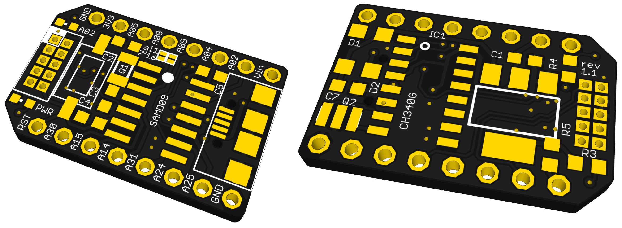
rev1.1
07/08/2016 at 20:04 • 0 commentsI just did order a new board revision. There were not much changes:
- added connection between DTR and PA15 (for reset over uart -> bootloader)
- changes wrong label (see errata)
- added revision number
- changes solder jumper to bigger ones
- some minor optimisationsAnd for ~2$ it was quite worth for me to test a for me unknown board house (perhaps you can guess it on the silkscreen color and plating)
![]()
I will share the new boards when I have tested them.
-
Using the bootloader from Jeremy g.
07/06/2016 at 19:30 • 1 commentThere is a project here on hackaday.io ( #MiniSam-Zero) which is using also a SAMD09. @Jeremy g. wrote also a bootloader for his project. And this boot loader can be also used for this board. In this log I will describe in short how. You should also take a look at Jeremy's project were he describes the usage of his bootloader in detail. For my needs I did also changed his bootloader a little bit: His and my boards are using different pins for a user LED. I did adapt his bootloader in this point.
I will only write additional notes here, Jeremy did a quite good job to describe the work flow in detail here.
Before you can use the bootloader you must flash your SAMD09 with it. For that you need some SWD-Programmer like the Atmel ICE or the Segger J-Link. you can either use the original bootloader from Jeremy or my modified version.
You can test if the bootloader is available by sending a 'i' to the SAMD09 over uart (115200 8N1) with some terminal program (I like Termite):
![]()
It should return some information (the green text).
Programs which you want to upload need to have an different start address. This can be set in Atmel Studio. For details see Jeremy's log.
After compiling your code you now should have a *.bin file somewhere in the output files. This file will be used by the bootloader's front end. This front end is some python2 script. If you did not used python before like me here are the steps I took (win7):
- Download python 2.x
- open a cmd window
- navigate to your python script path (like: C:\Python27\Scripts)
- activate pip (package manger) with: python -m pip install -U pip
- install pyserial with: pip install pyserial
Now you should be able to use Jeremy's uplaoder script. Just place it in the same directory as you *.bin file an execute it in this file like:
upload.py -c com10 -b 115200 -i Blink.bin
The script asked you to rest the SAMD09 and asks if the boot led (with my modified bootloder the on board user LED) is on. The bootled is on if you are in bootloader mode. To get ther you have to pull down PA15 during reset or connect it to the DTR pin of the CH340 (2nd not test by me yet).When the script is ready. Your program should run after a reset. You can find all files I used including a test *.bin file in my github repository. But all of Jeremy's stuff should also work (as long the programs are not to big for the smaller flash of the SOIC SAMD09).
If you do not get out of the bootloader-mode (LED is always on) connect PA15 to 3.3V during reset. This will happen if you use Jeremy's or an very early version of my modified bootloader.
-
USB-UART bridge is also tested
06/19/2016 at 16:55 • 0 commentsOne of the main features of this board is now also tested. I used the CH340 UART to USB bridge on the bottom side of the board successfully. The CH340 is connected to PA24 (used as TX of SERCOM1) and PA25 (used as RX of SERCOM1). I wrote some functions, so my main routine looks quite simple:
int main(void)
{
    SystemInit();
    // SAMD09 TX-PA24-SERCOM1_PAD2
    pin_set_peripheral_function(PINMUX_PA24C_SERCOM1_PAD2);
    // SAMD09 RX-PA25-SERCOM1_PAD3
    pin_set_peripheral_function(PINMUX_PA25C_SERCOM1_PAD3);
    UART_sercom_init(SERCOM1);
    UART_sercom_simpleWrite(SERCOM1, 'H');
    UART_sercom_simpleWrite(SERCOM1, 'e');
    UART_sercom_simpleWrite(SERCOM1, 'l');
    UART_sercom_simpleWrite(SERCOM1, 'l');
    UART_sercom_simpleWrite(SERCOM1, 'o');
    UART_sercom_simpleWrite(SERCOM1, '!');
    UART_sercom_simpleWrite(SERCOM1, 0xa);
    while (1) ;
}
The complete code can be seen here. This is not prefect code but works well for me for testing.
-
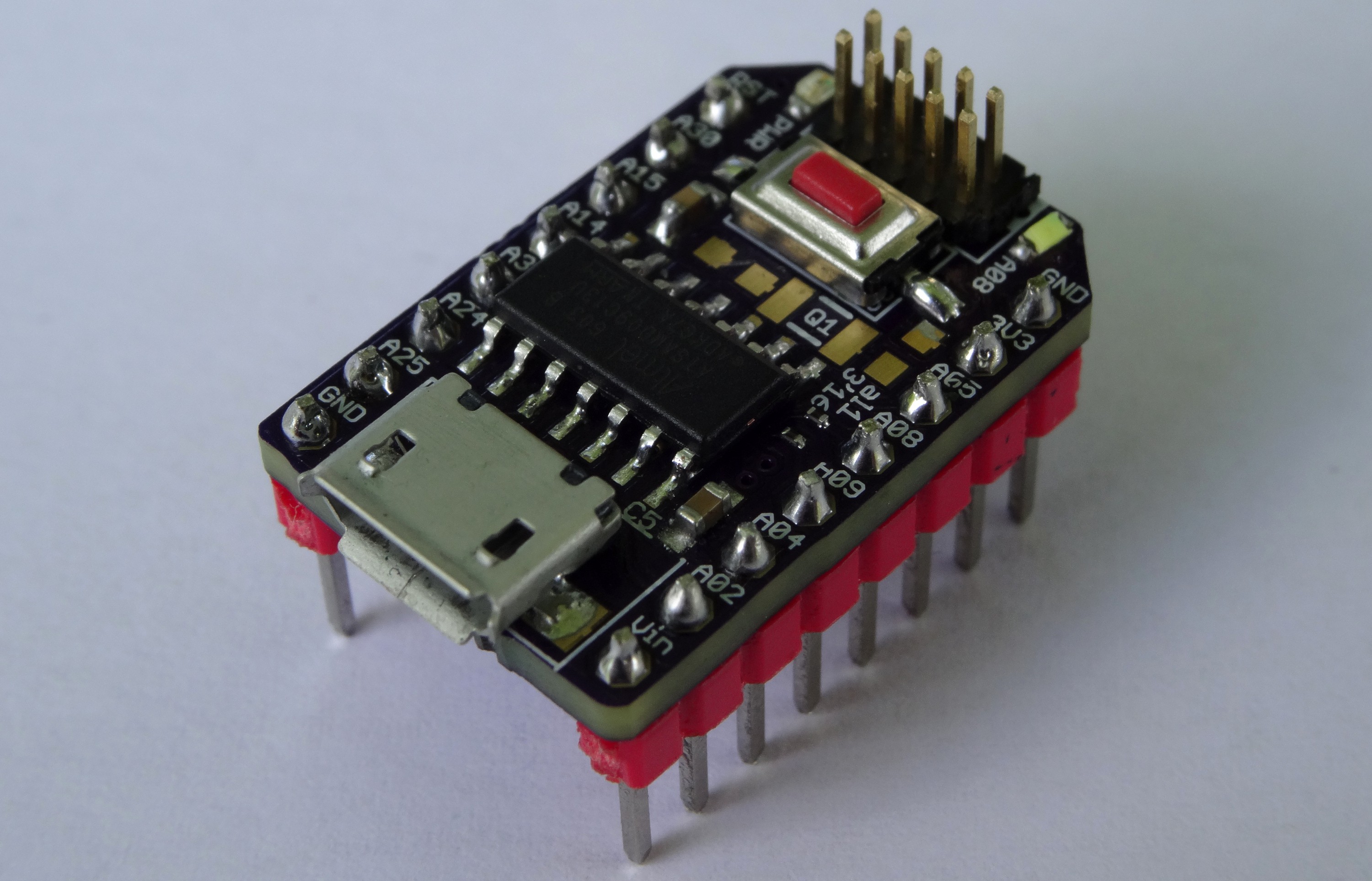
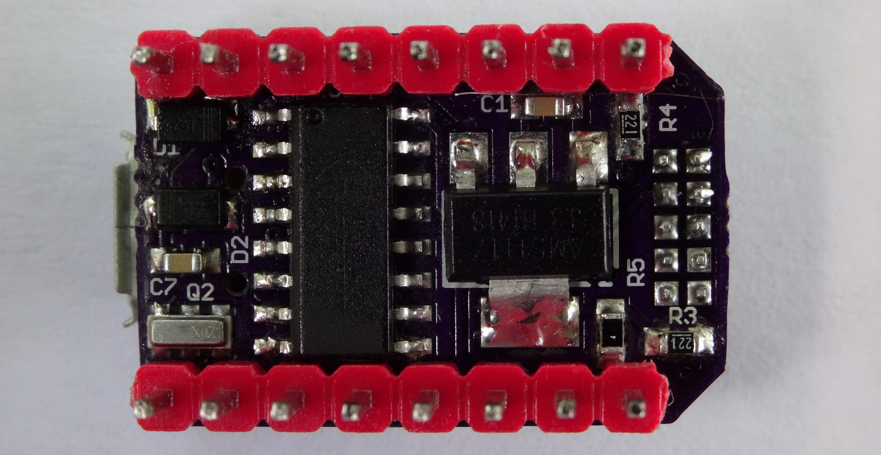
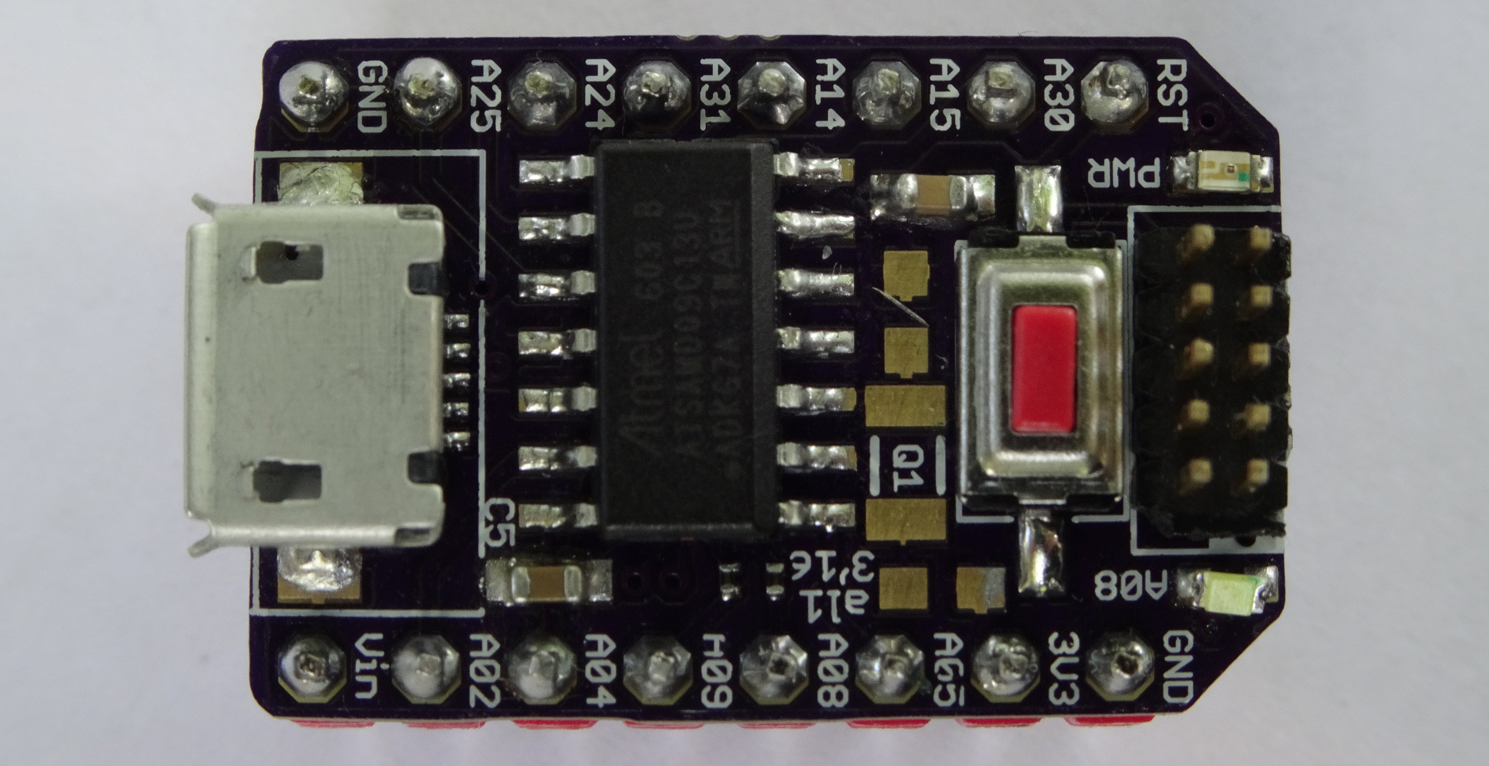
More pictures
06/19/2016 at 15:19 • 0 comments![]()
![]()
![]()
![]()
-
It's blinking
06/18/2016 at 14:14 • 0 comments -
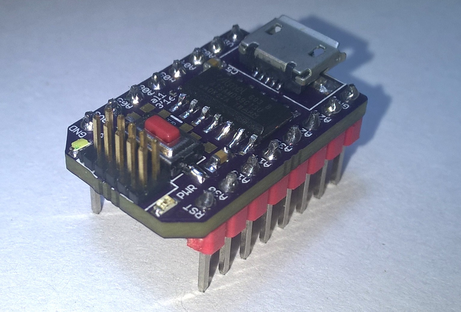
Suddenly a soldered unit appears
06/17/2016 at 18:25 • 0 commentsAlthough this is the first log. The first unit is now ready: More information / pictures / code is coming soon.
![]()
 The connections are quite simple: Power, GND and for wires for the SPI bus (MOSI, MISO, CLK and !SS). The logic analyser on the right is also connected to the SPI bus for debugging. I will upload the early stages of the used code to github also.