 Steve Schuler
Follow me on Twitter: @SteveSchuler20 and right here on Hackaday: KRA5H

My original LaserOscope was featured on Hackaday. Ethan Zonca, author of the article wrote the following about my LaserOscope:
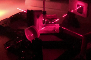
"If you’ve ever used an old-school analog oscilloscope (an experience everyone should have!) you probably noticed that the trace is simply drawn by a beam that scans across the CRT at a constant rate, creating a straight line when there’s no signal. The input signal simply affects the y-component of the beam, deflecting it into the shape of your waveform. [Steve] wrote in to let us know about his home-built “oscilloscope” that works a lot like a simple analog oscilloscope, albeit with a laser instead of a CRT.
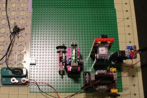
[Steve]’s scope is built out of a hodgepodge of parts including Lego, an Erector set, LittleBits, and a Kano Computer (based on a Raspberry Pi). The Pi generates a PWM signal that controls the speed of a LittleBits motor. The motor is hooked up to a spinning mirror that sweeps the laser across some graph paper, creating a straight laser line.
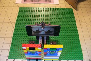
After he got his sweep working, [Steve] took a small speaker and mounted a mirror to its cone. Next he mounted the speaker so the laser’s beam hits the mirror on the speaker, the spinning sweep mirror, and finally the graph paper display. The scope’s input signal (in this case, audio from a phone) is fed into the speaker which deflects the laser beam up and down as it is swept across the paper, forming a nice oscilloscope-like trace.
While [Steve]’s scope might not be incredibly usable in most cases, it’s still a great proof of concept and a good way to learn how old oscilloscopes work."
One of the commentators pointed out:
"What an incredibly complex way to do a simple task! A 32-bit computer with 512 MB of RAM and a multitasking operating system does nothing but blink an LED, which through an optocoupler and amplifier, drives a motor. This much could be done with a battery, a variable resistor, and a motor. And he didn’t just use a $30 Raspberry Pi, he used a $150 kit that includes an RPi for this task, in addition to at least $100 for Little Bits kit.
But all of that aside, I don’t understand why [Ethan Zonka] refers to this project as a “home-built ‘oscilloscope’ that works a lot like a simple analog oscilloscope”, when it IS in fact an analog oscilloscope, by pretty much any reasonable definition of ‘oscilloscope’."
Yes, it is expensively over-engineered. The actual point of this build was to demonstrate optocoupling (I got tired of building magnetic stirrers and wanted to try something completely different). There are much simpler ways to demonstrate optocoupling, but how often does one get the chance to build an analog oscilloscope out of a disparate pile of toys, however Rube Goldberg-esque, just for fun?
In my previous project "An Experiment to Combine Lego and Snap Circuits" I designed a simple Snap Circuits circuit to spin a mirror and in this project I'm revisiting the Laser oscilloscope proof of concept with a lot fewer parts.
Build the graph paper target
The graph paper screen is easy to build with a piece of cardboard, graph paper, and a large binder clip:


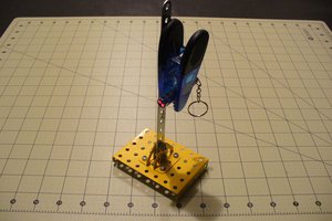
I used a magnetic chip clip to clamp the laser pointer switch (a press switch) in the on position and attach the laser pointer to the Erector set mount. Unfortunately, there are plastic grips on the chip clip that interfere with the smooth rotation of the chip clip against the Erector set strip. So, I added a neodymium magnet from a magnetic keychain that I took apart and the keychain magnet lets me smoothly rotate the chip clip.
Parts Needed:
Magnetic chip clip
(Optional) neodymium magnet
Erector Set Parts:
1 Strip, 1 1/2", 15 hole
1 Base plate, seven hole by five hole
2 Triangle brackets
4 Small bolts
2 Medium bolts
6 Nuts
12 washers
1 Spanner
1 Hex wrench


Speaker Mount
Parts Needed
Erector set right angle bracket 3-hole (mine is a bit more than 90°)
Erector set nut
Computer case thumbscrew
Chip Clip

I used a knife...
Read more »

 Frédérik Berthiaume
Thanks, Jerry, for liking my project!