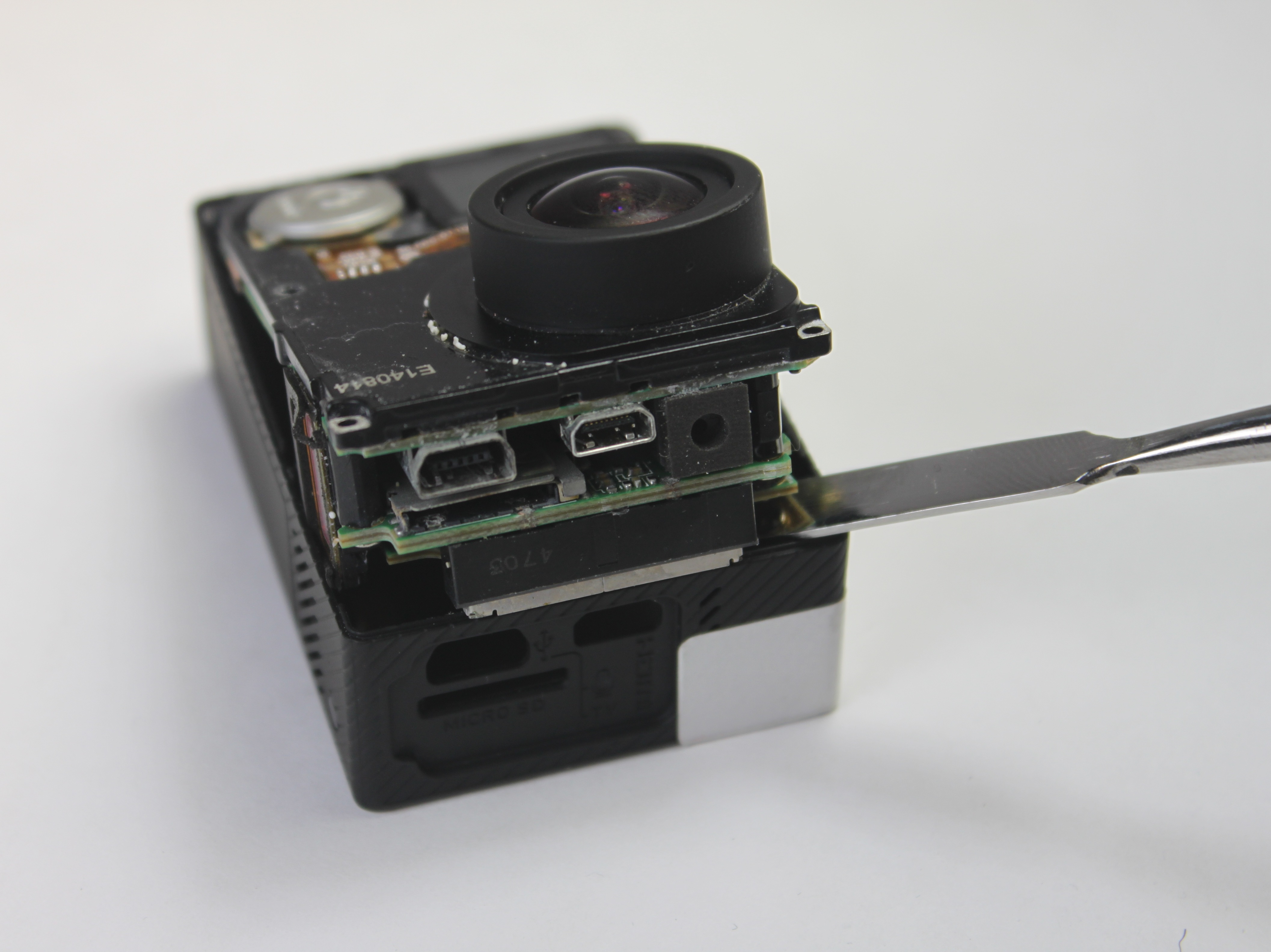
1. Remove the SD card, battery and the front cover using a plastic tool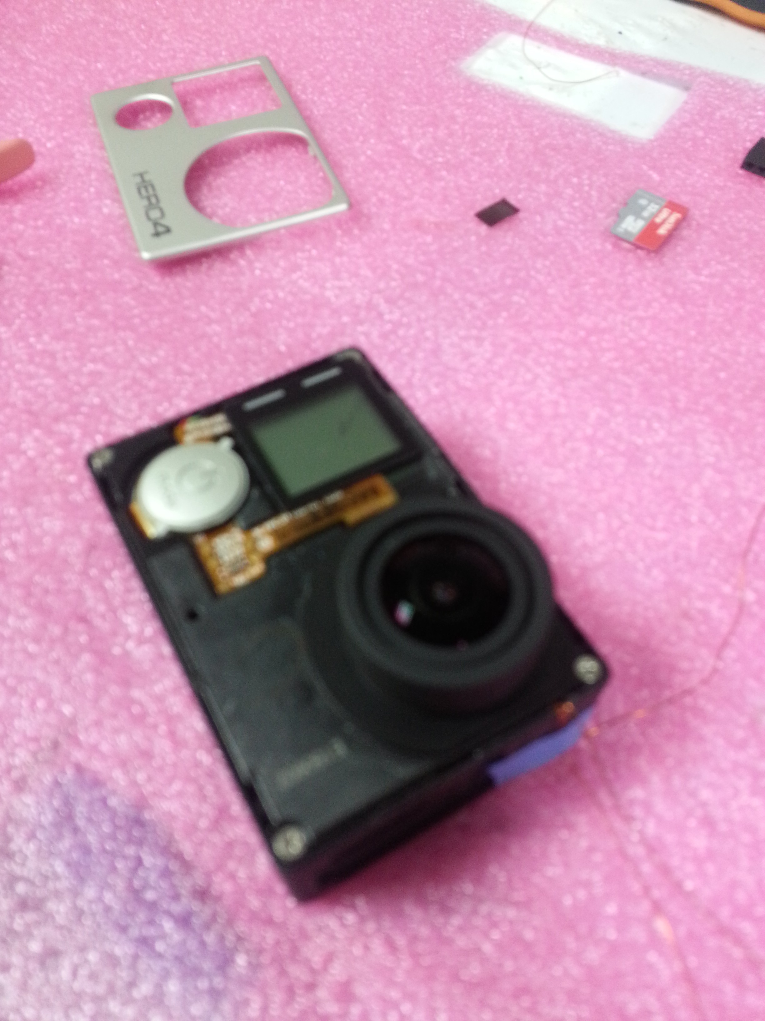
2. Remove the screws ( remember that the shortest one is the botton left corner screw) and the plastic power button
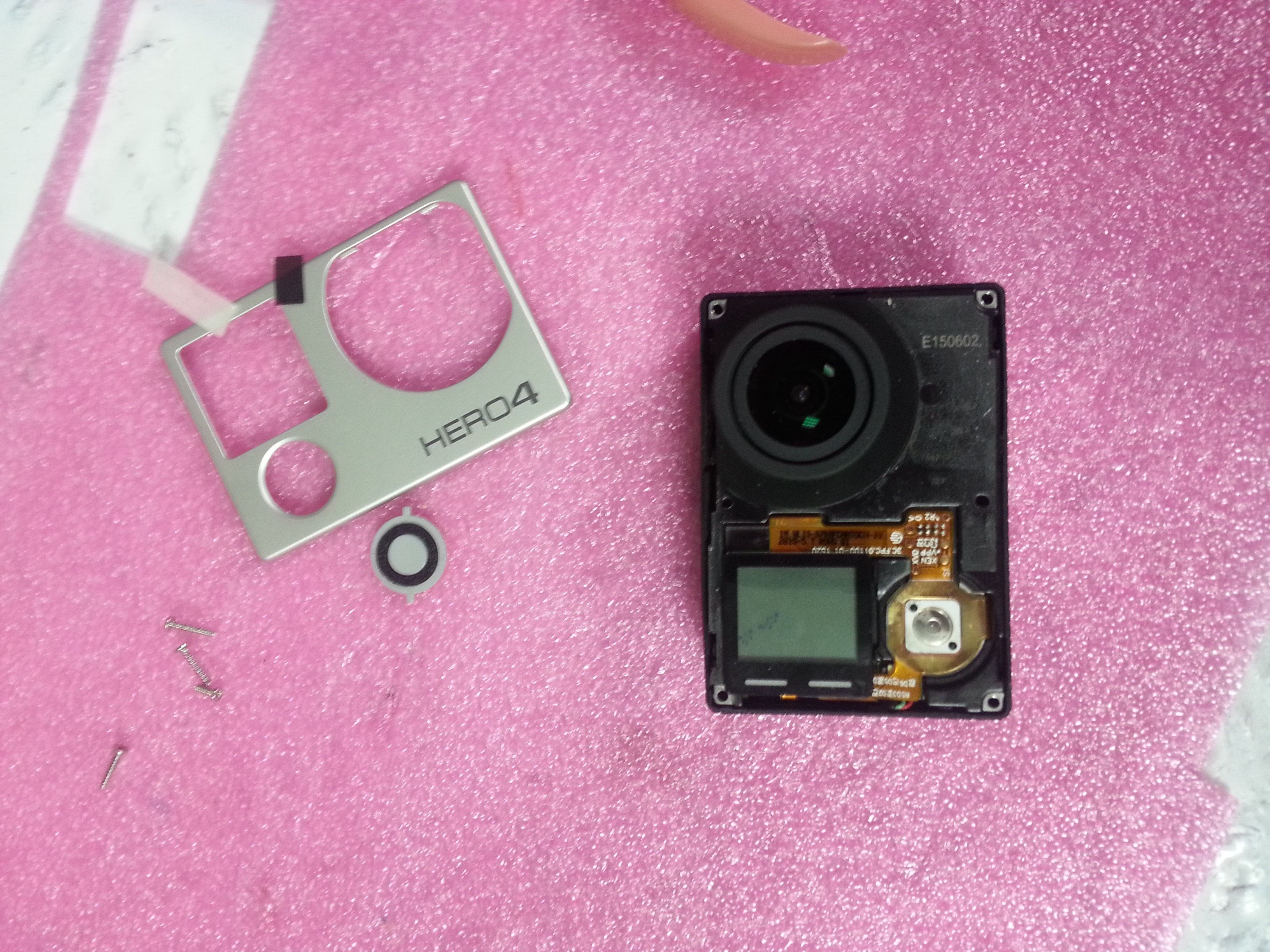
3. Pell off the front LCD pushing form the back with a plastic tool. Take care because this step could break the LCD.
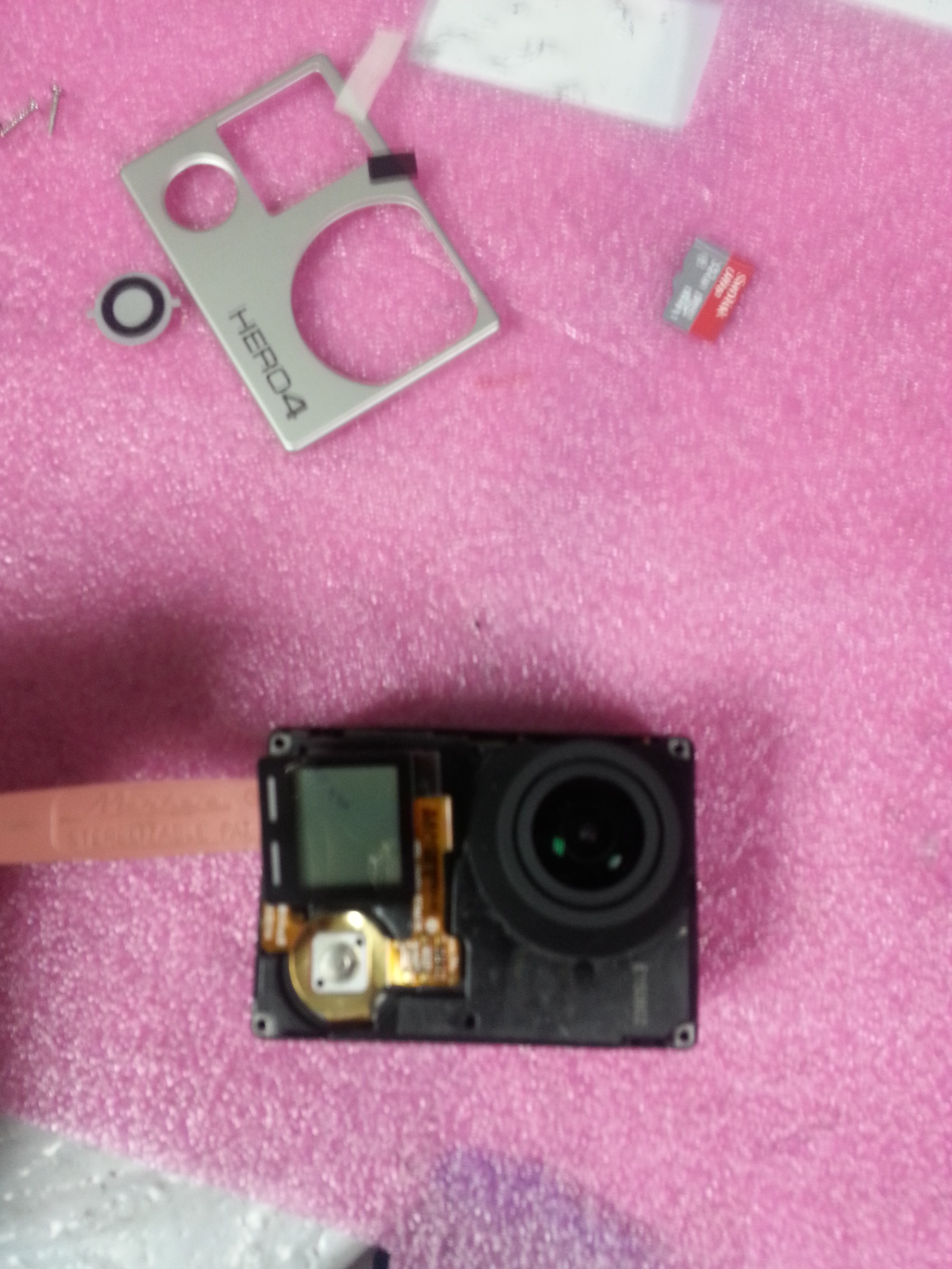
4. Now we have access to the Power connector and three ribbon cables. Discoonect it
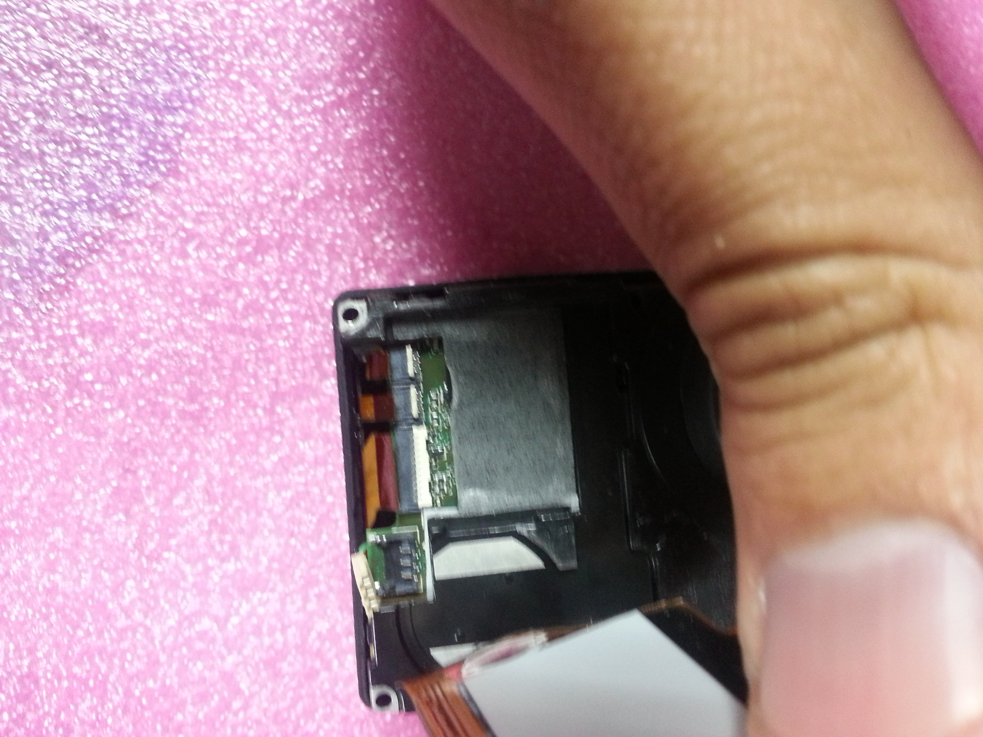
5. Remove the motherboard out of the camera housing
6. Now we got the back housing circuits exposed
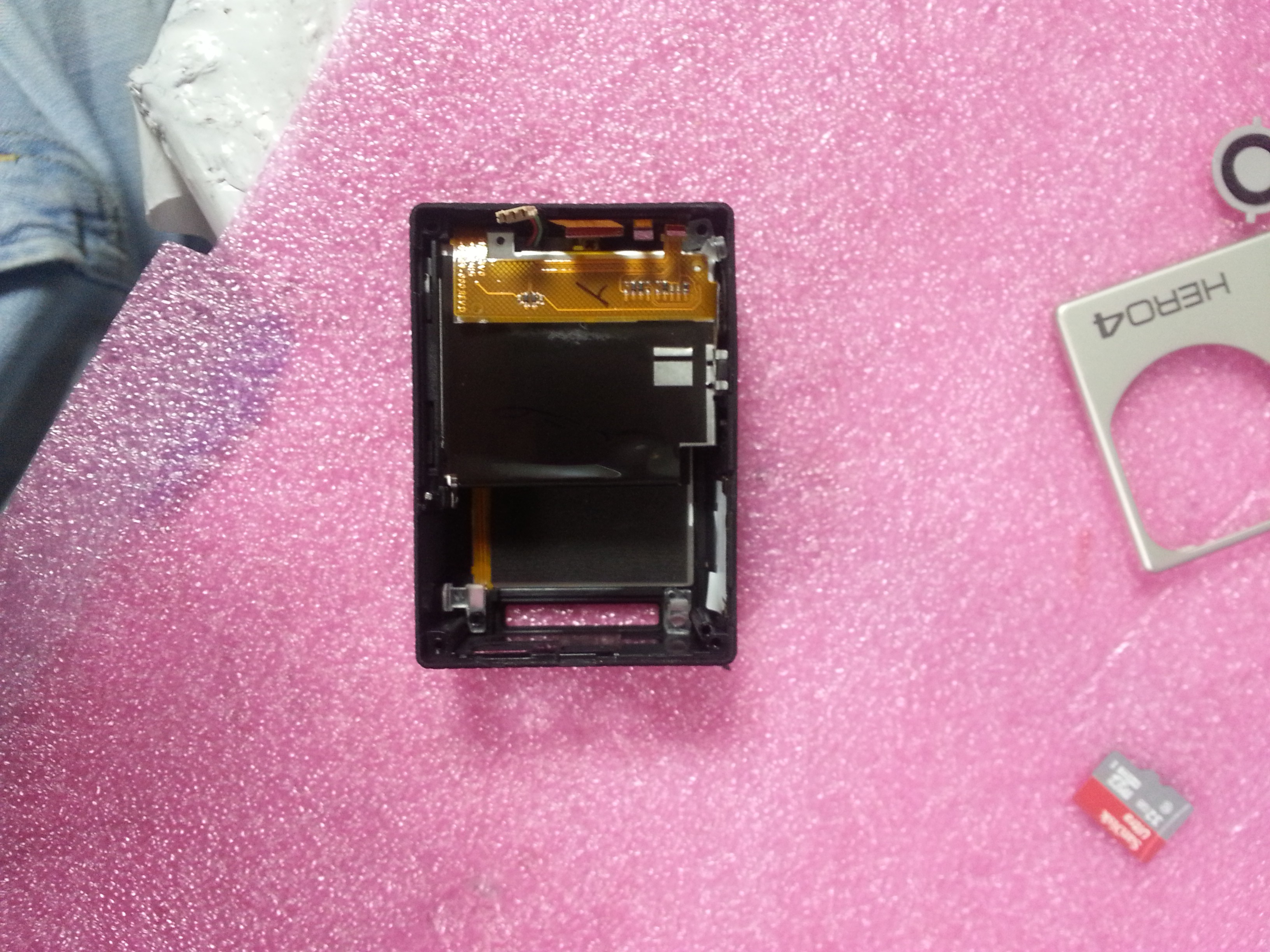
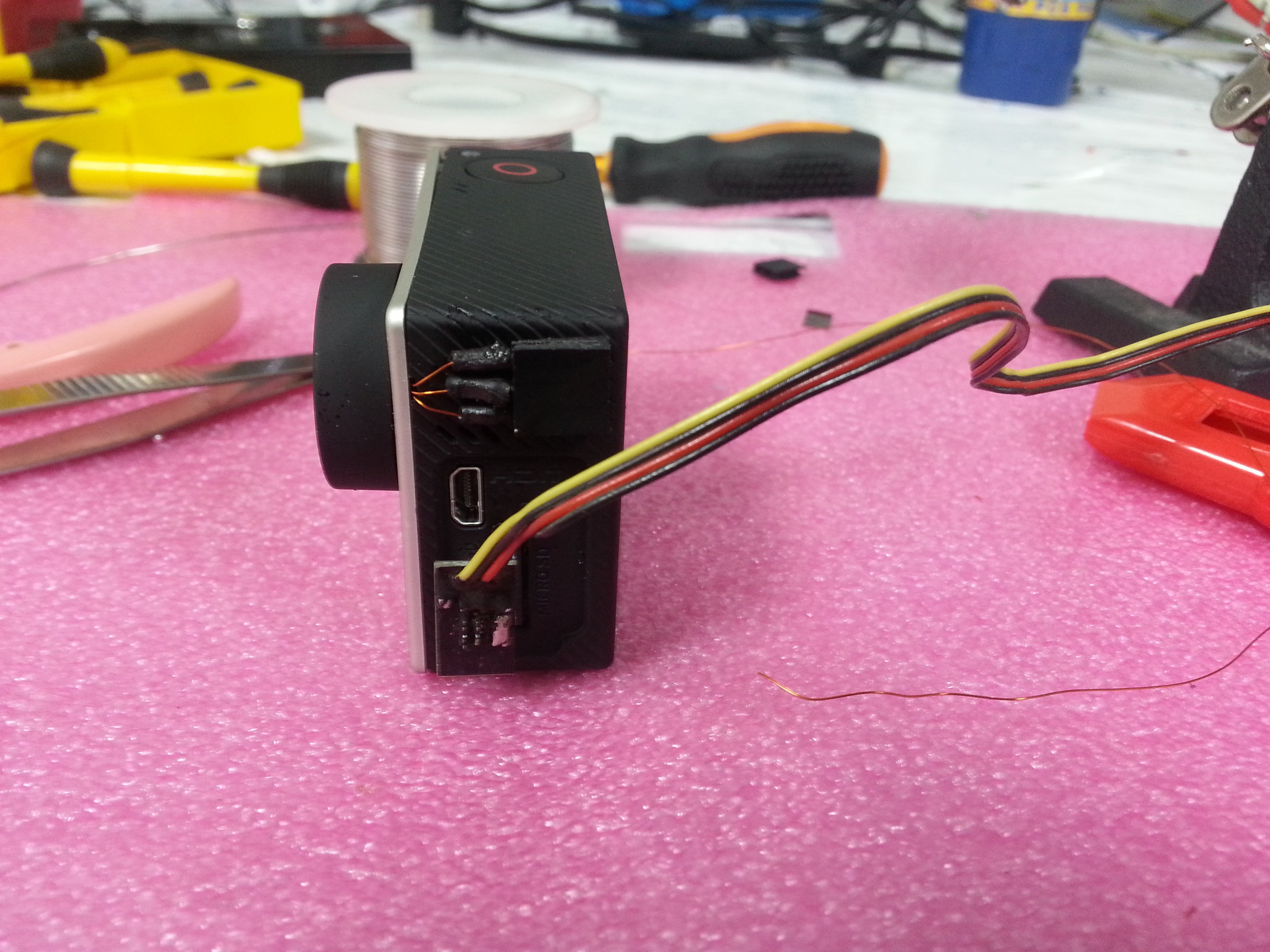
7. Carefully solder two enameled wires to this points ( left one is the setting button and right one is the shooter button )
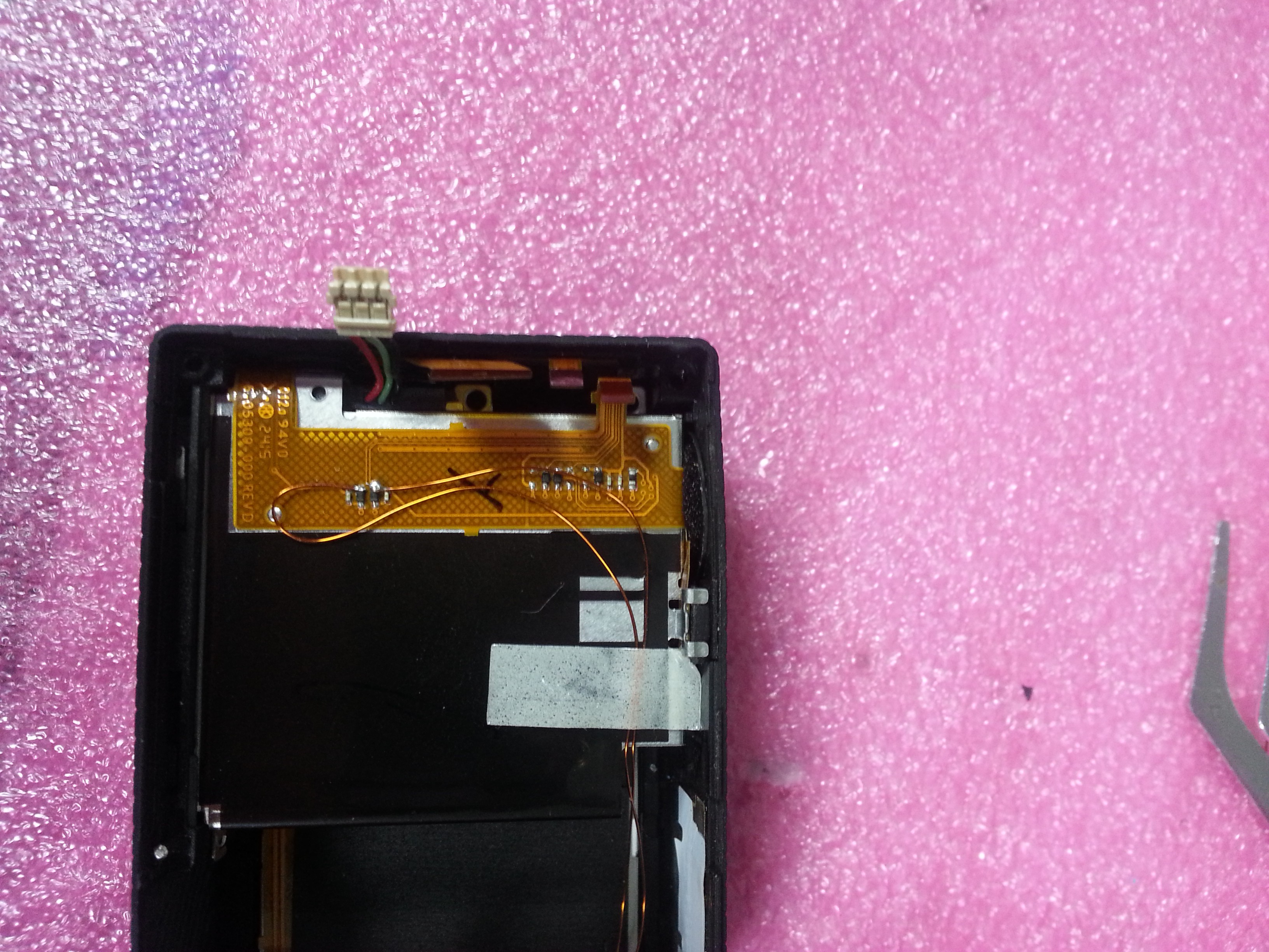
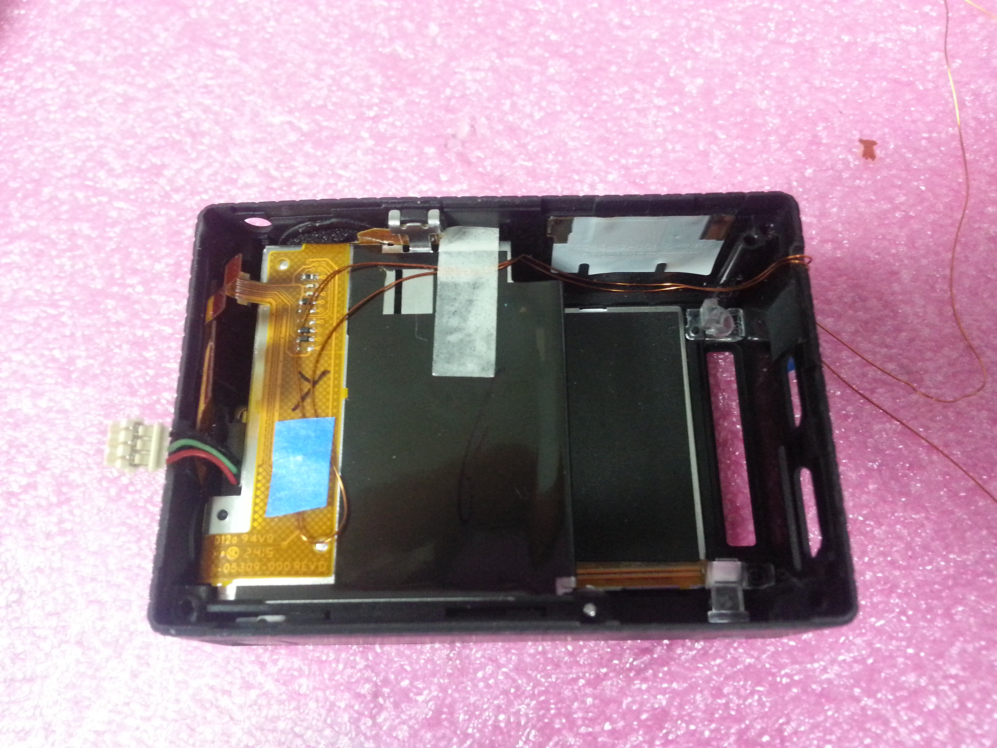
8. Route the cables to outside. Make a little groove in the right housing side.
9. Take the back side of the main board. Take a wire and snap it together in the socket with the position #10 of the ribbon cable, this is the power/mode button. ( In this step you also could get the GND in the position #9 of the ribbon )
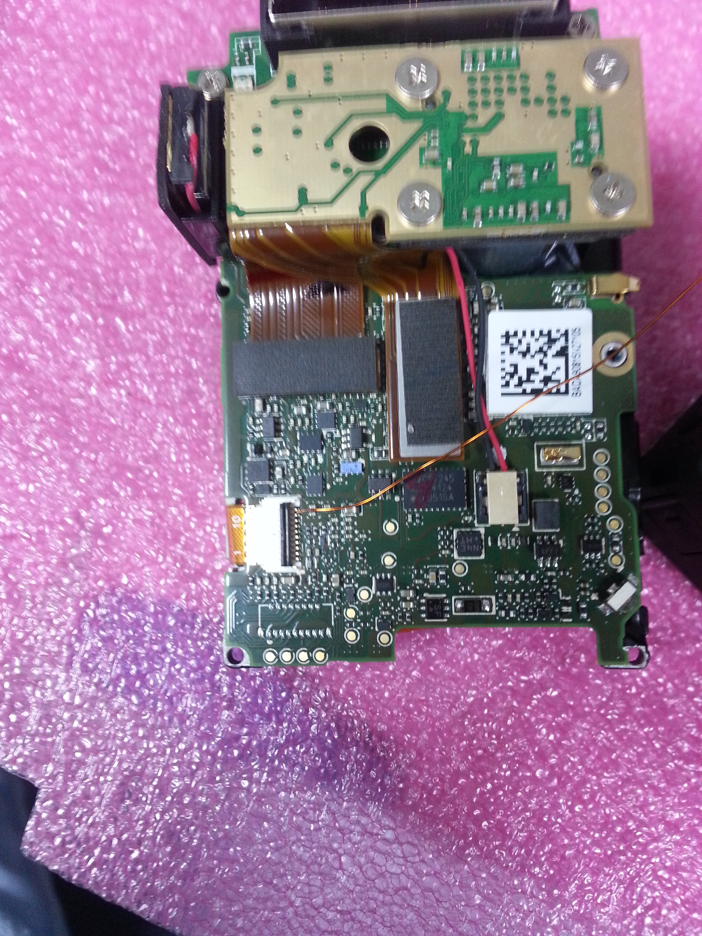 10. Route the cable to the right side of the camera
 11. Put it back the main board in to the camera housing.
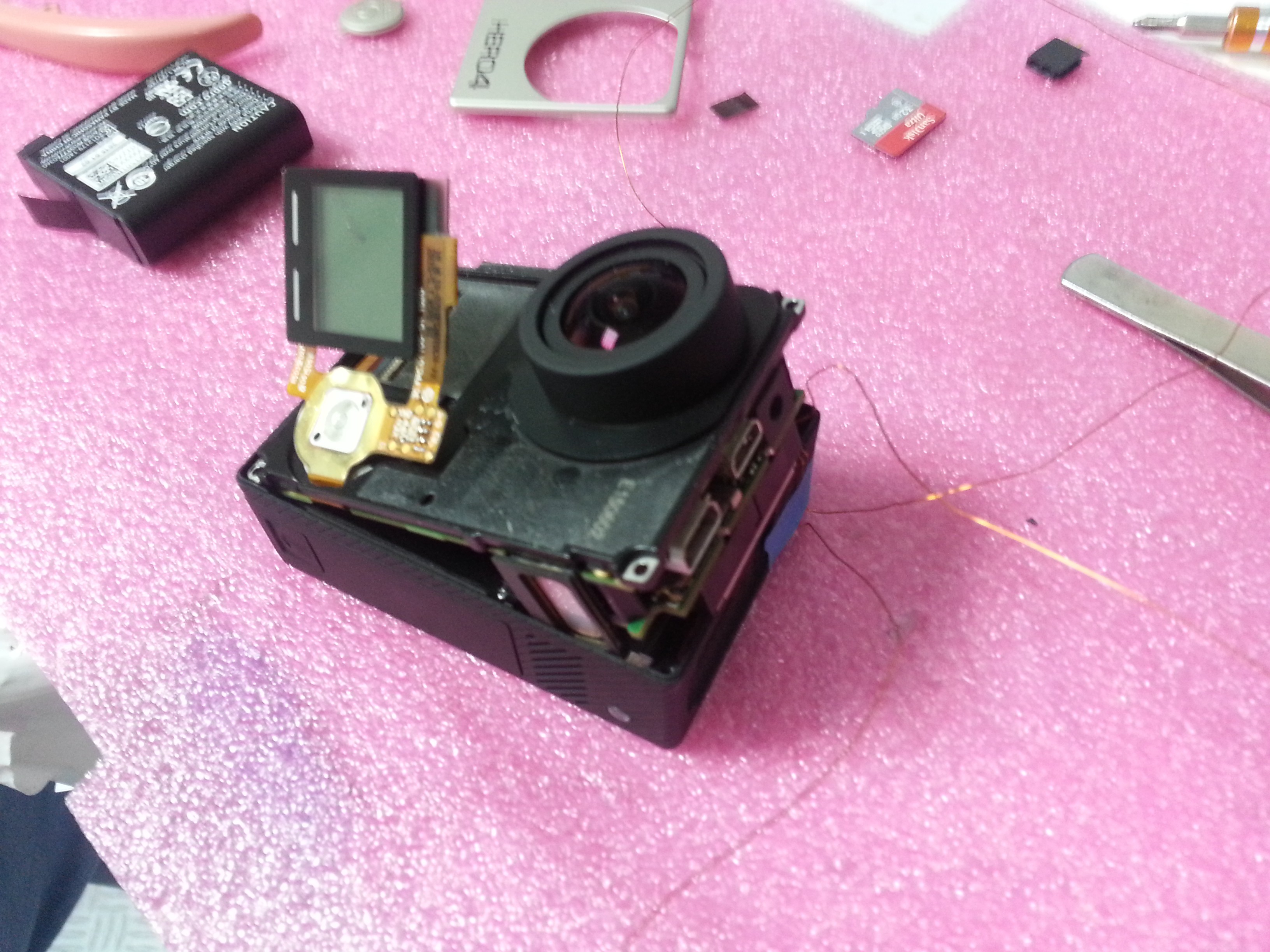
12. Reconnect the ribbon and the power plugs behind the front lcd.
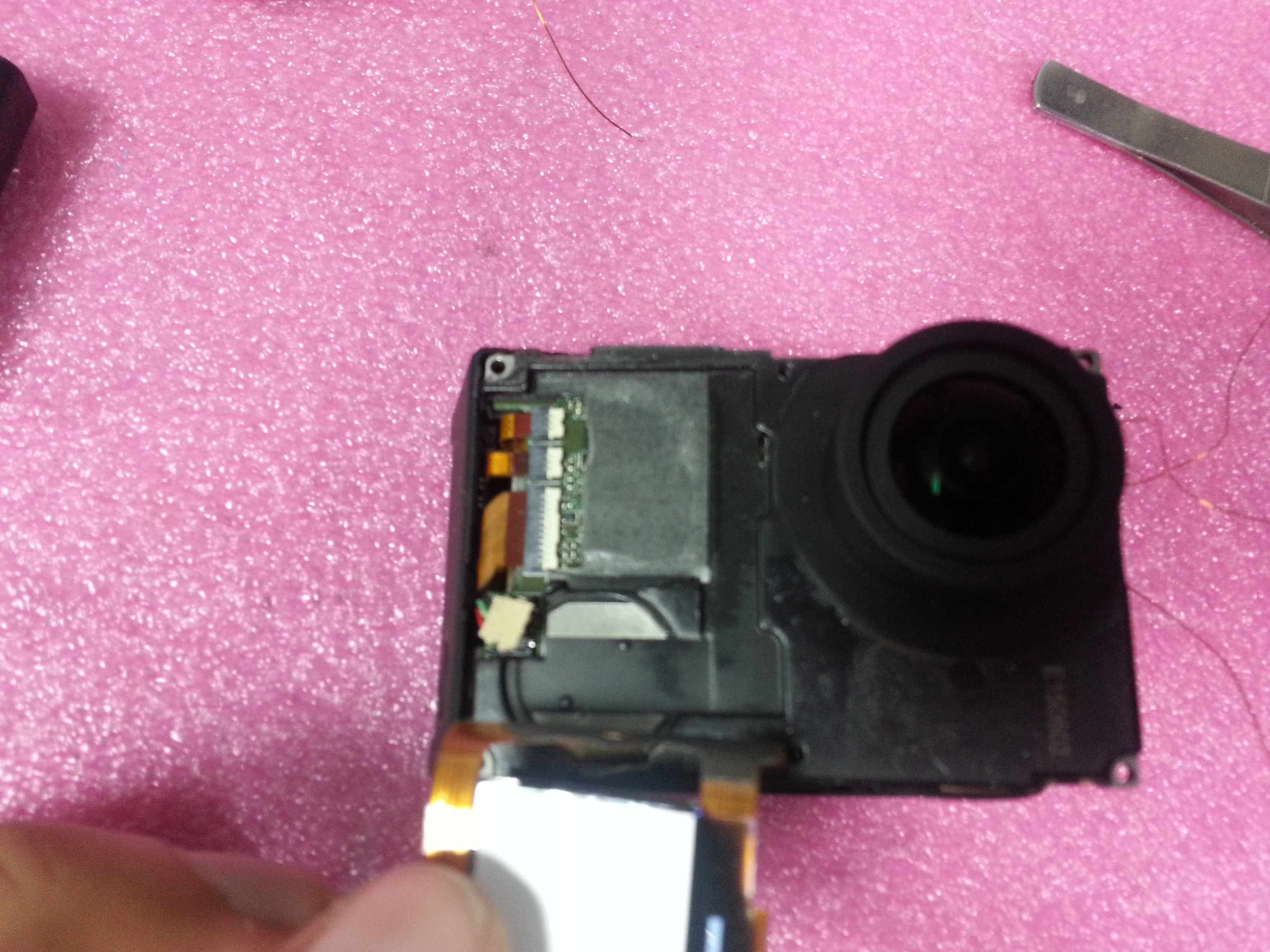 13. Put the lcd in its place and the plastic button. Finally the four screws ( remember the shoter one in the left bottom corner)
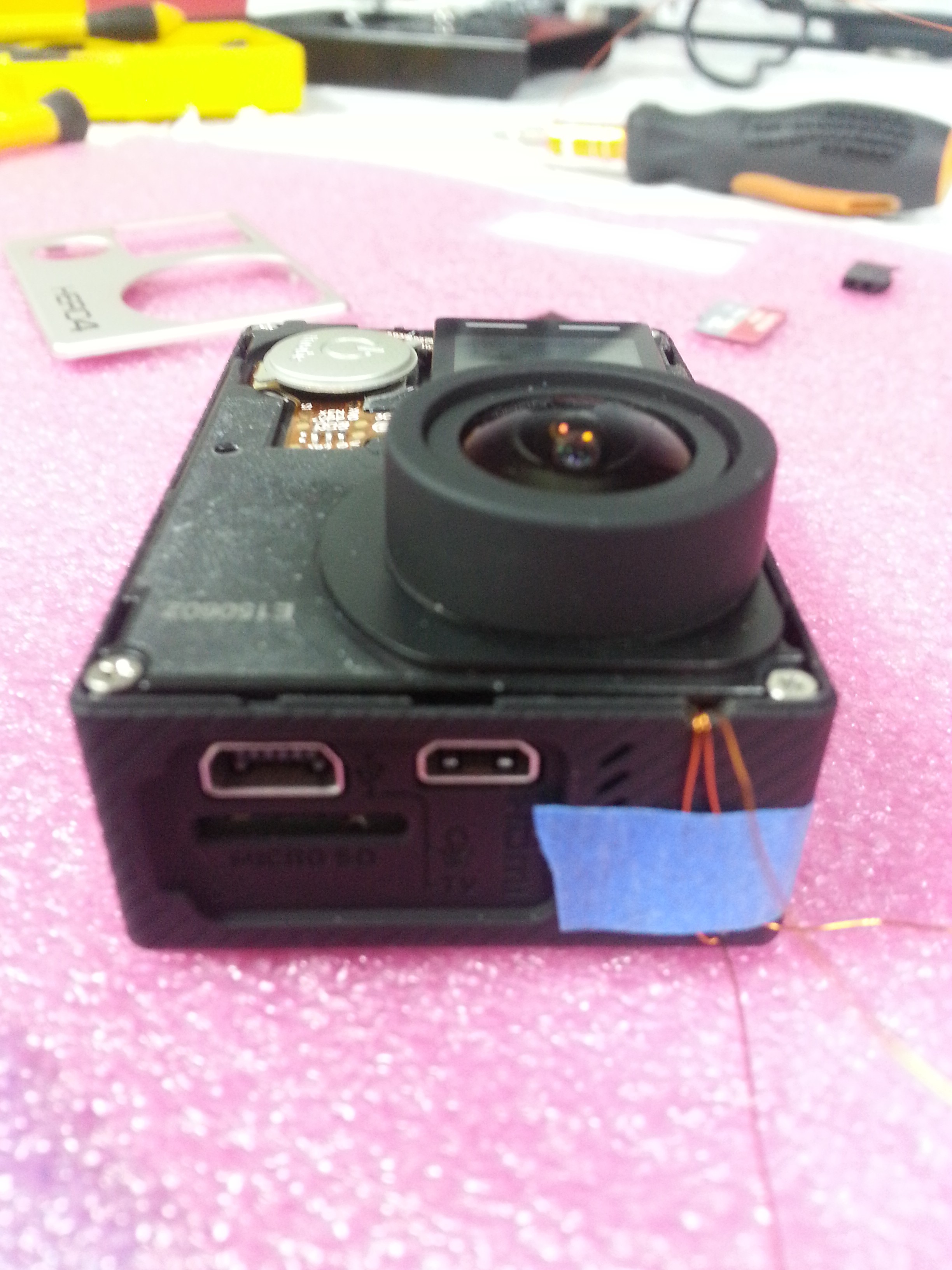 Final Step: Put the front case and solder a female conector to the button cables.
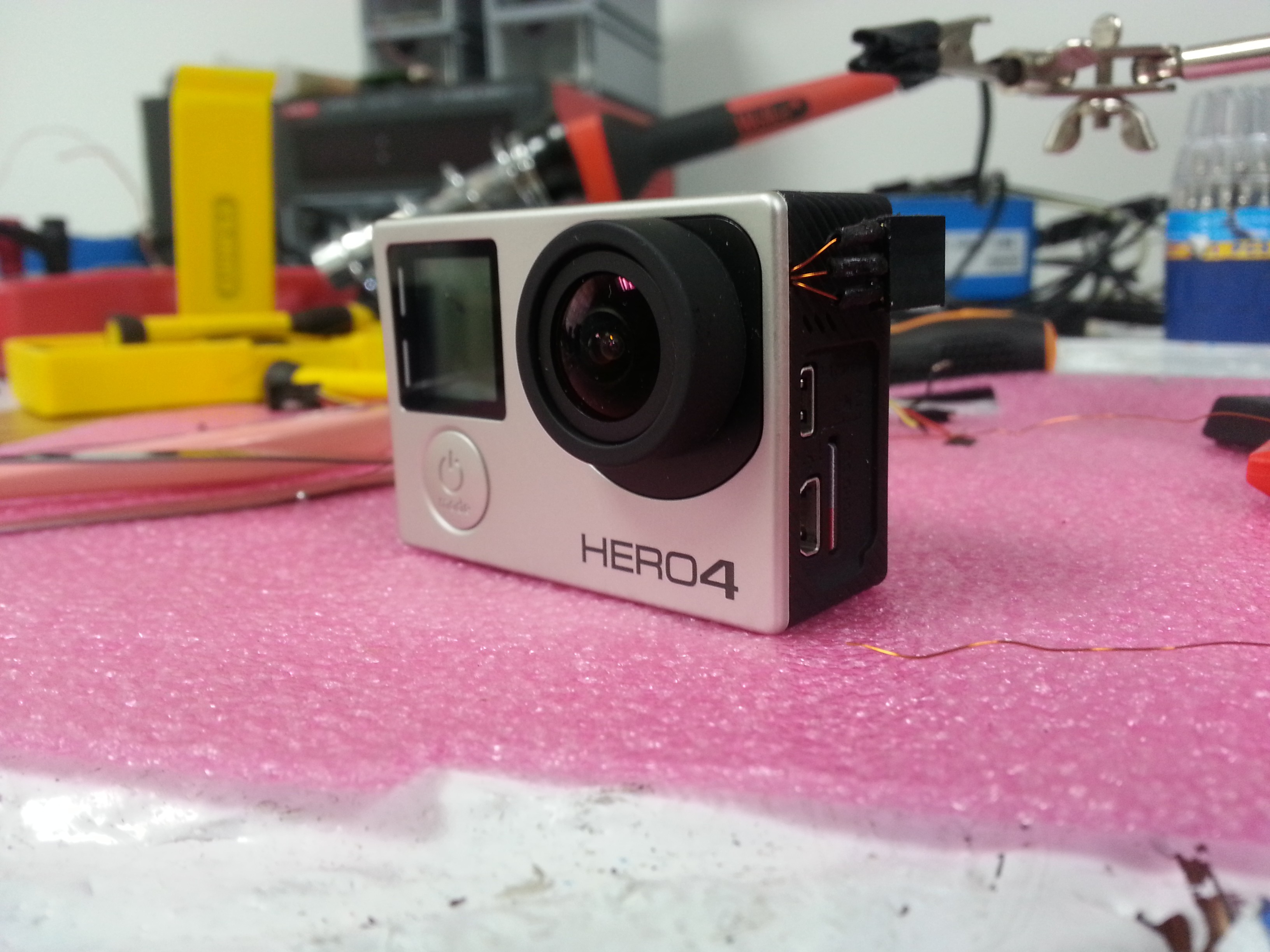
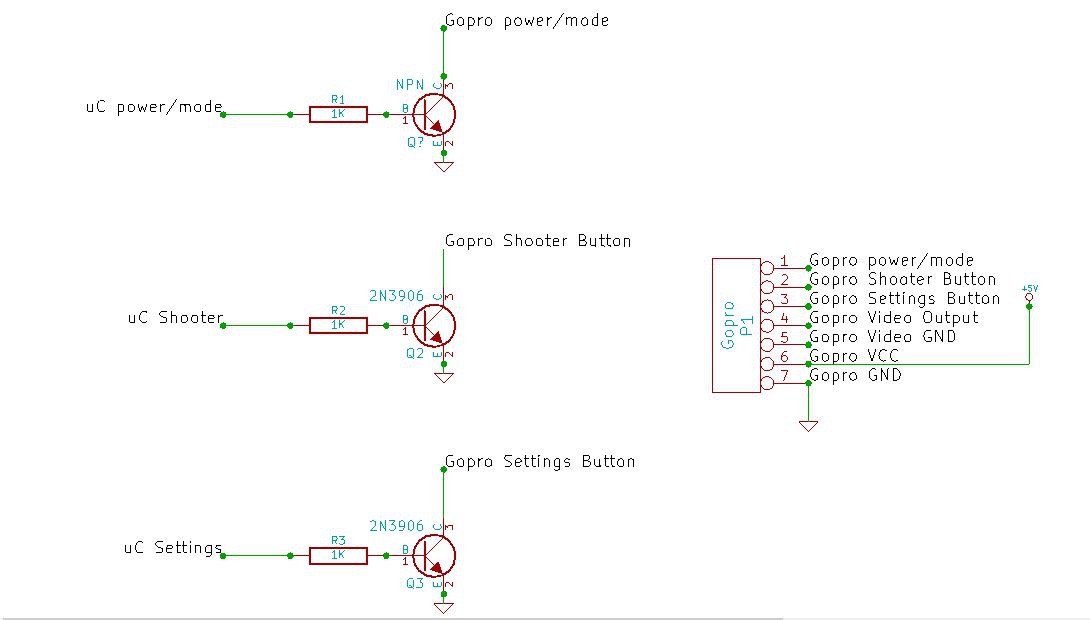
Finally i got the powe/ mode button, the shooter button and the settings button in a row on the female connector. I'm also using the Gopro AV cable to get video, GND, and add an external power supply.
This is my circuit to control the camera, I've tested with an Intel Galileo board 5V gpios.
 AndresRengifo

 jimmy
jimmy
 John Leeman
 ric866
 Mike Rigsby
Hi, thanks for this guide. Been doing this sucessfully on several Hero 4 cameras using transistor switches and Arduino Nano. I'm now up to implement this on Hero 7 - Have you tried this?