dudeskidaddy
-
Power Schematic, Wiring & XT90 Anti-Sprak
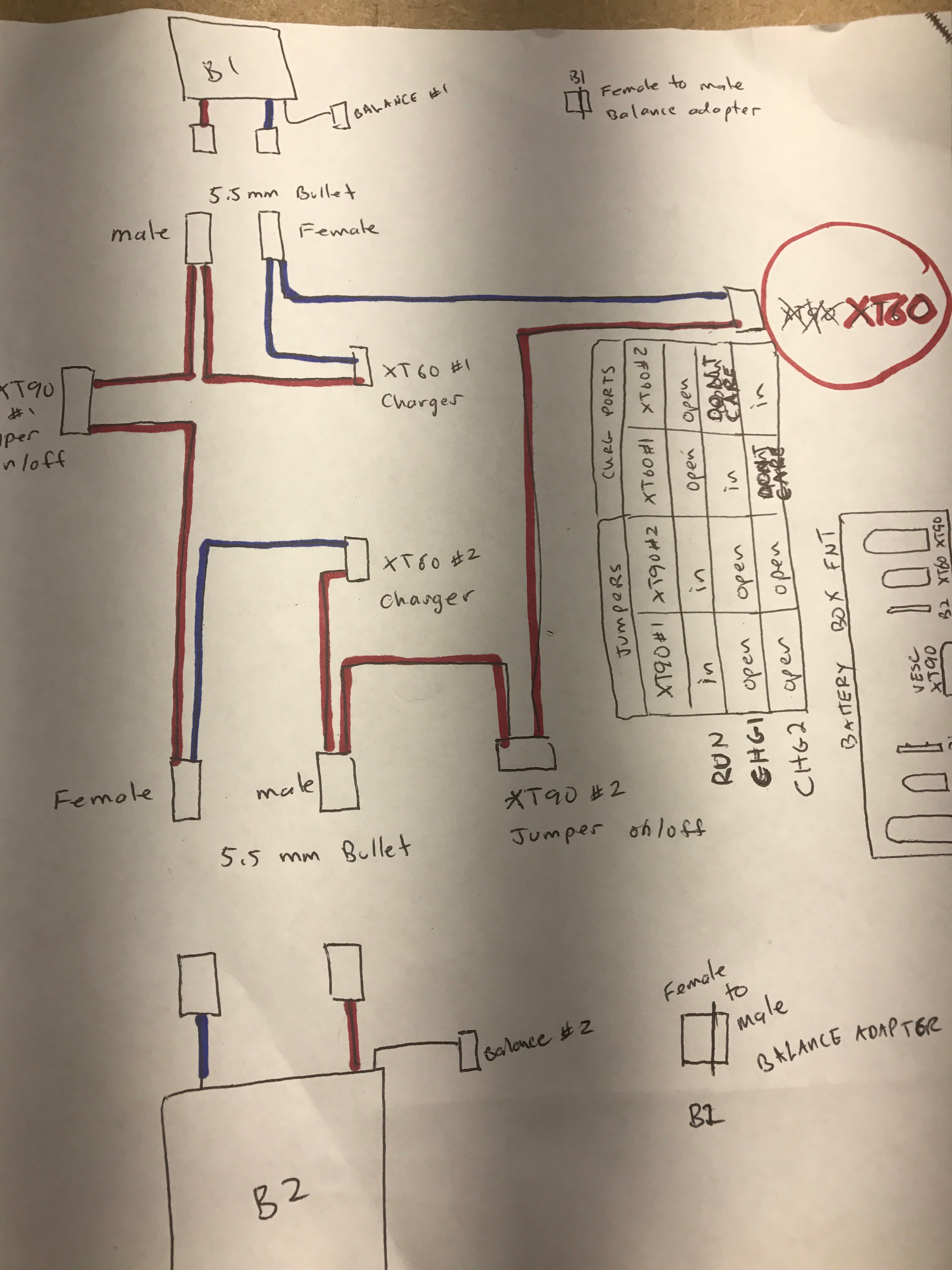
10/09/2016 at 22:46 • 0 commentsWiring Schematic for the battery box 2x5s series = 10s
The idea is to be able independently balance charge 2 batteries that are connected in series to the VESC without having to open up the box. You can't just put a charger on the series output and performa balance charge. The batteries need to be isolated. Ideally, all the ports to both ARM and balance charge are accessible from the outside and done in such a way that prevents accidentally hooking up the wrong thing and causing a fire...or worse. All the wiring has to fit in the space and the ports will be mounted and glued through the box.
![]()
There will be 2 XT90 "Anti-Spark" Jumpers that both need to be plugged in to "arm" the board. When the jumpers are out the batteries are completely disconnected from each other and the positive terminal to the VESC. Both batteries could then be charged at the same time or independently via the XT60 ports. Again, all these XT ports and both battery's 5s balance ports will be permanently mounted through the battery box and we won't need to open the box or unplug any wires.
![]()
Why use both XT60 and XT90?
The jumper ports (XT90) are intentionally different types than the charger and output ports (XT60). This is to prevent accidentally shorting PWR/GND with the arming jumpers which would be bad.
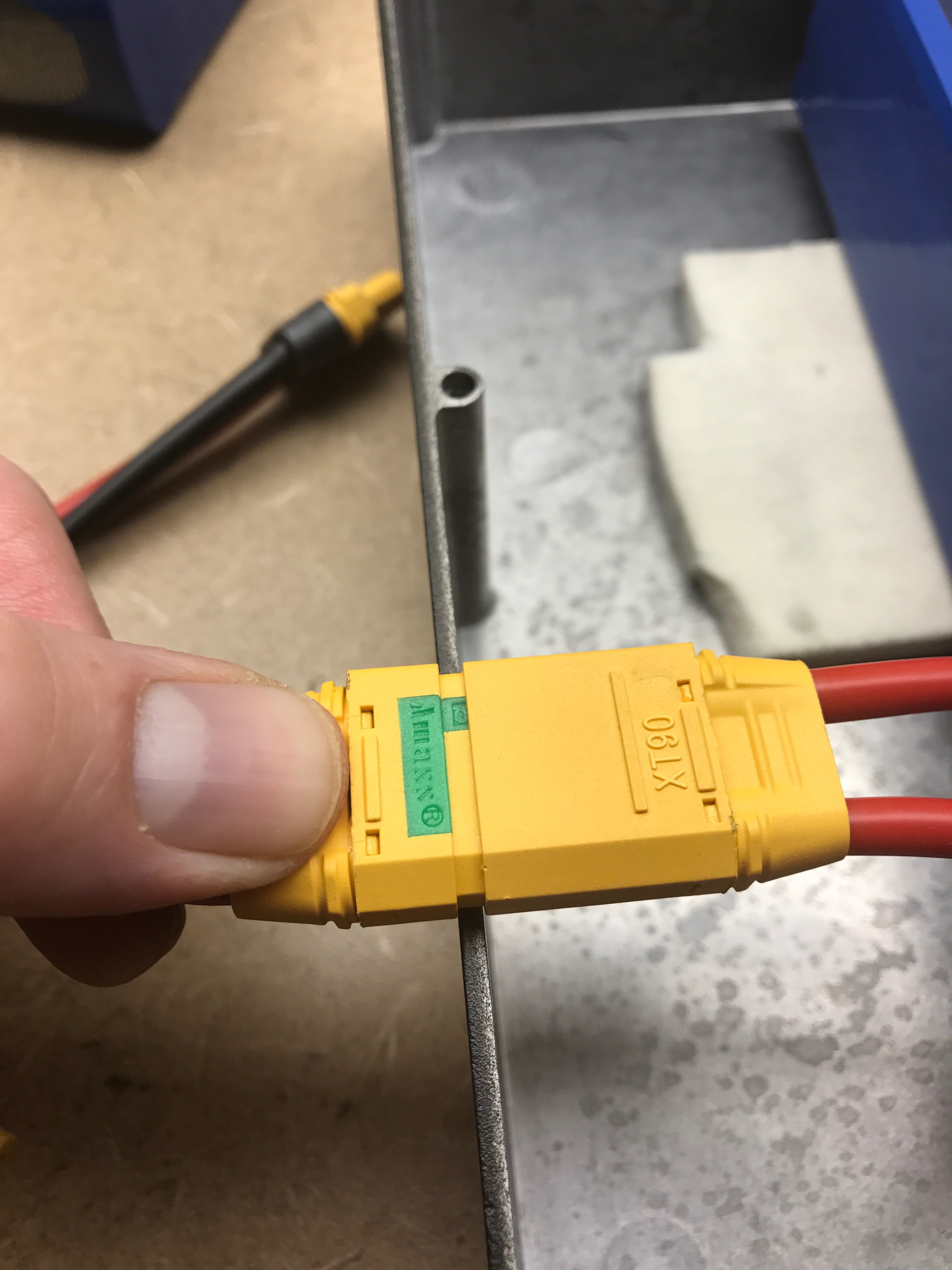
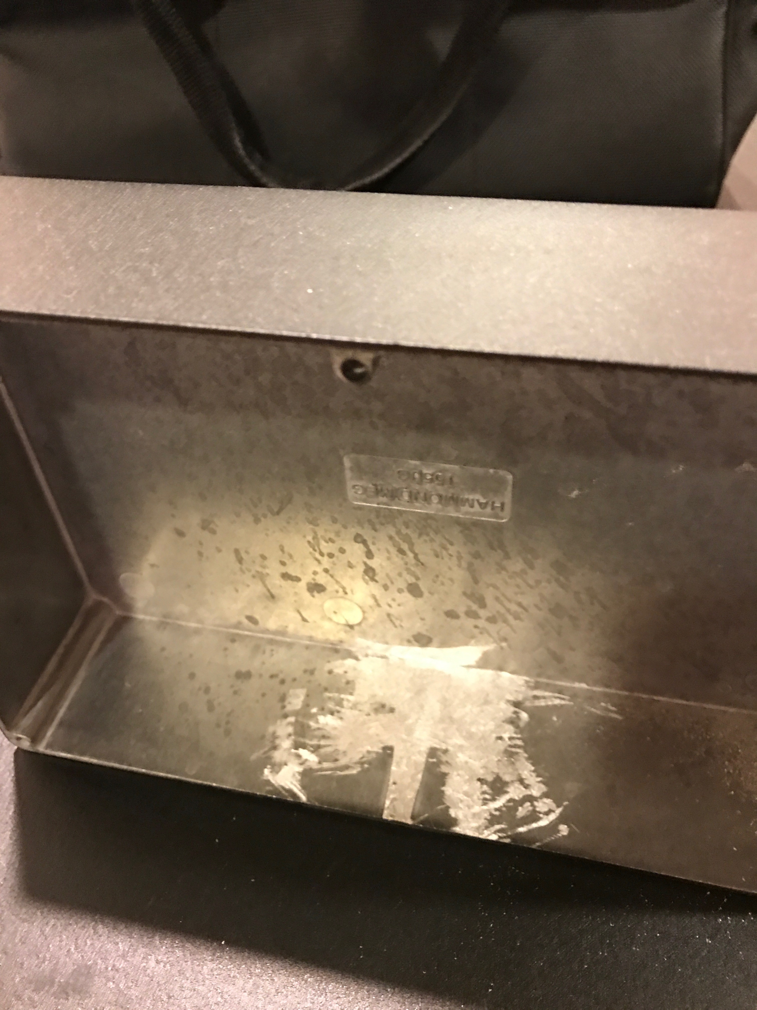
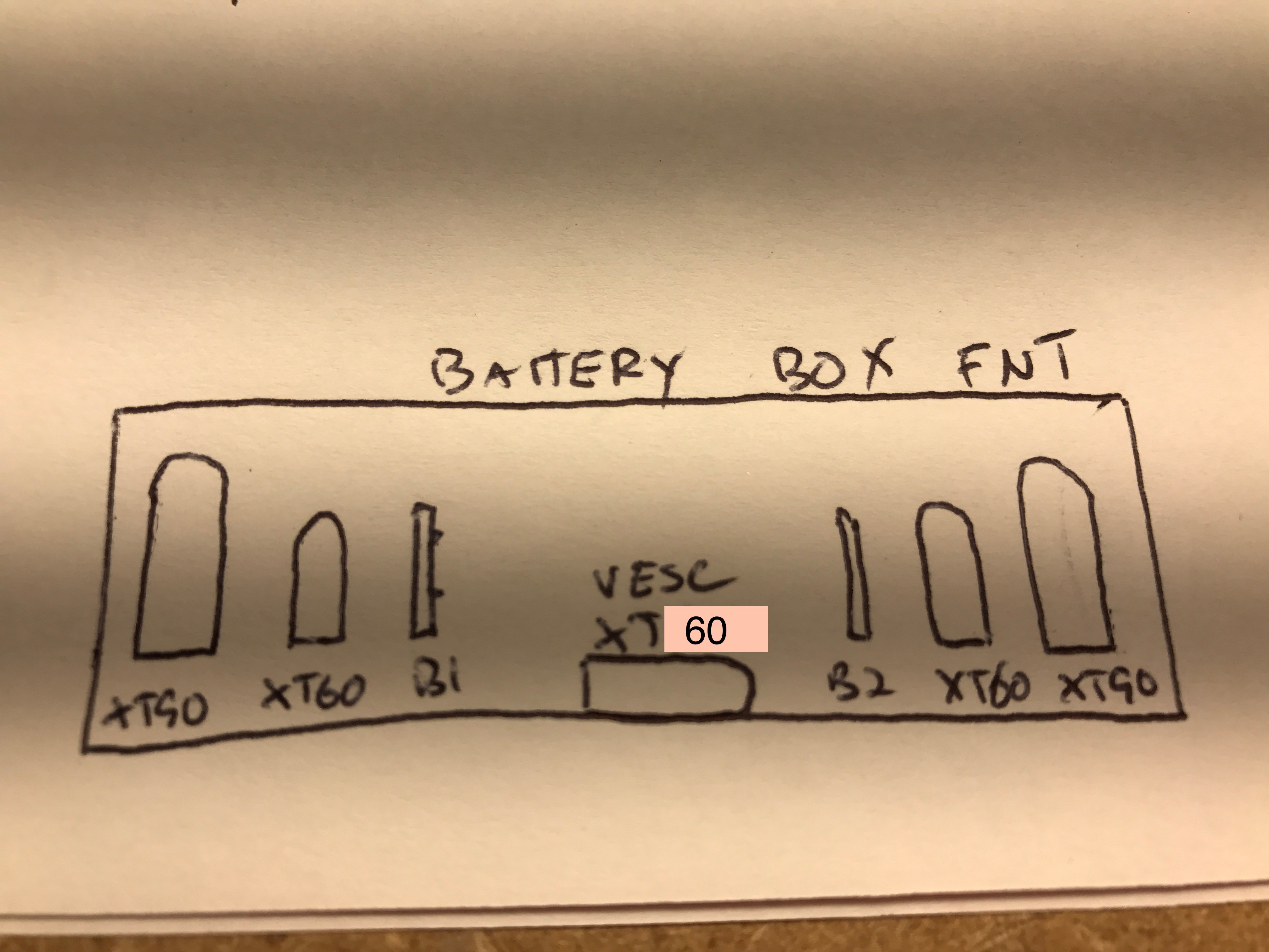
![]() Terminal ports...on the back side of the battery box. This side faces backward on the board. The jumpers would be dangerous if you put one on a charge or output port. But since the jumpers are XT90, they can only be used to connect to the XT90 jumper port and won't fit the others.
Terminal ports...on the back side of the battery box. This side faces backward on the board. The jumpers would be dangerous if you put one on a charge or output port. But since the jumpers are XT90, they can only be used to connect to the XT90 jumper port and won't fit the others. Here is the whole mess all soldered and hooked up to the LIPOs.
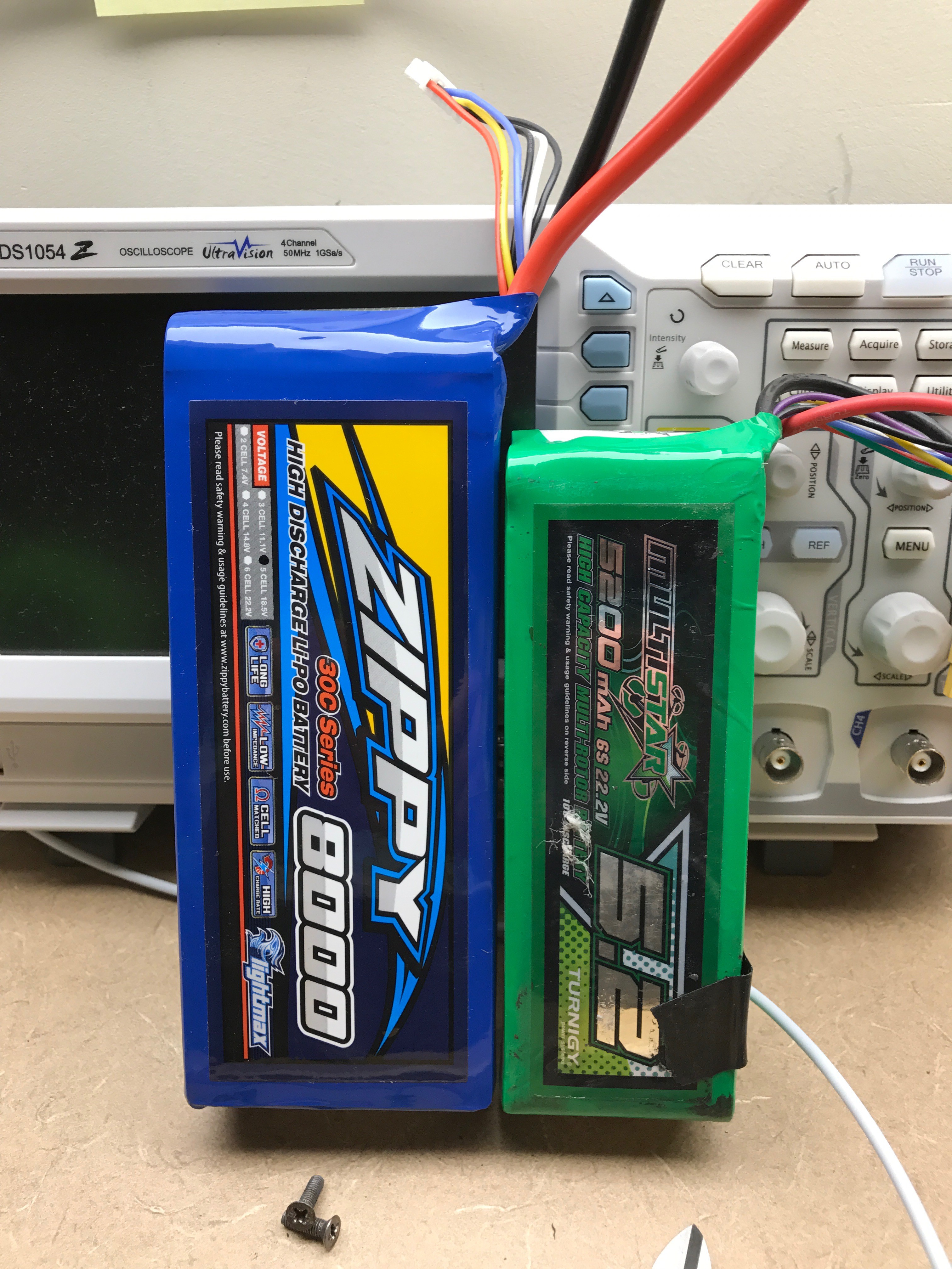
![]() Both 10s batteries ( storage-charged at 50%) showing 37.81V. Note the 2 XT90 Jumpers in place. All this stuff has to fit in the small area in front of the batteries. I could have used shorted wires, but based on past experience I personally think it's easier to fit longer ones. Usually it's getting them to bend the way you need them to is the hardest part...not fitting all that wire..and longer wires are easier to bend. We'll see. I haven't mounted to the box yet and crammed it all in. I think it will fit.
Both 10s batteries ( storage-charged at 50%) showing 37.81V. Note the 2 XT90 Jumpers in place. All this stuff has to fit in the small area in front of the batteries. I could have used shorted wires, but based on past experience I personally think it's easier to fit longer ones. Usually it's getting them to bend the way you need them to is the hardest part...not fitting all that wire..and longer wires are easier to bend. We'll see. I haven't mounted to the box yet and crammed it all in. I think it will fit. A problem with the XT90 anti-spark jumper:
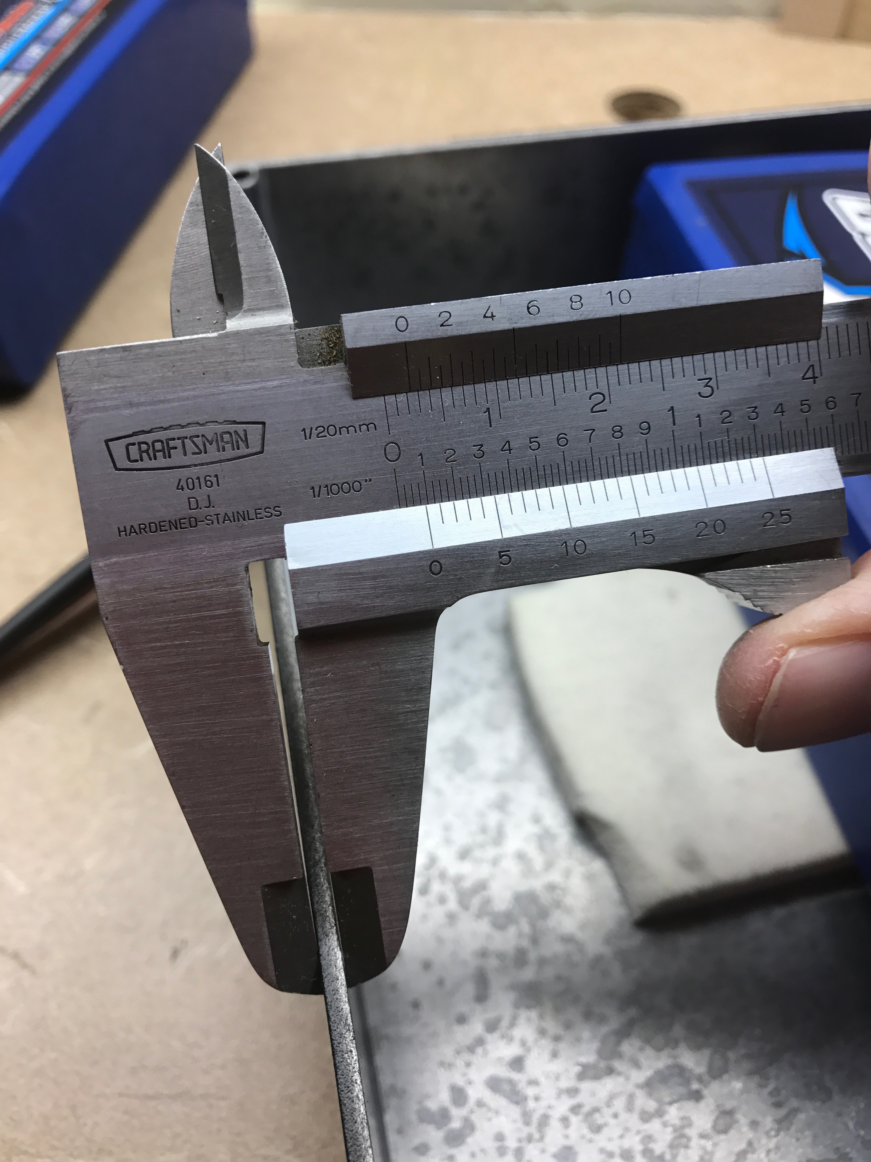
Before connecting the batteries, I tested each port using the multimeter (Ohms) . I just wanted to make sure I soldered it according to the schematic and in particular didn't do something stupid that would short the batteries. This much energy in one place kind of freaks me out a little bit. Anyway, turns out the XT90 Anti-spark jumpers don't connect unless they are inserted ALL THE WAY! This is a problem since the box is about 2.5mm thick and will hold off the plug by that much. The jumpers are not conducting in this configuration...they have to be completely seated to work.
![]()
Thats the port on the left that will be mounted through the box and glued. The jumper is on the right. Like before, the mounting method takes advantage of the XT90's raised edge to provide extra resistance to pulling forces...glue isn't enough. Since these jumpers are going on and off every time the board is used...they have to be rock solid.
![]()
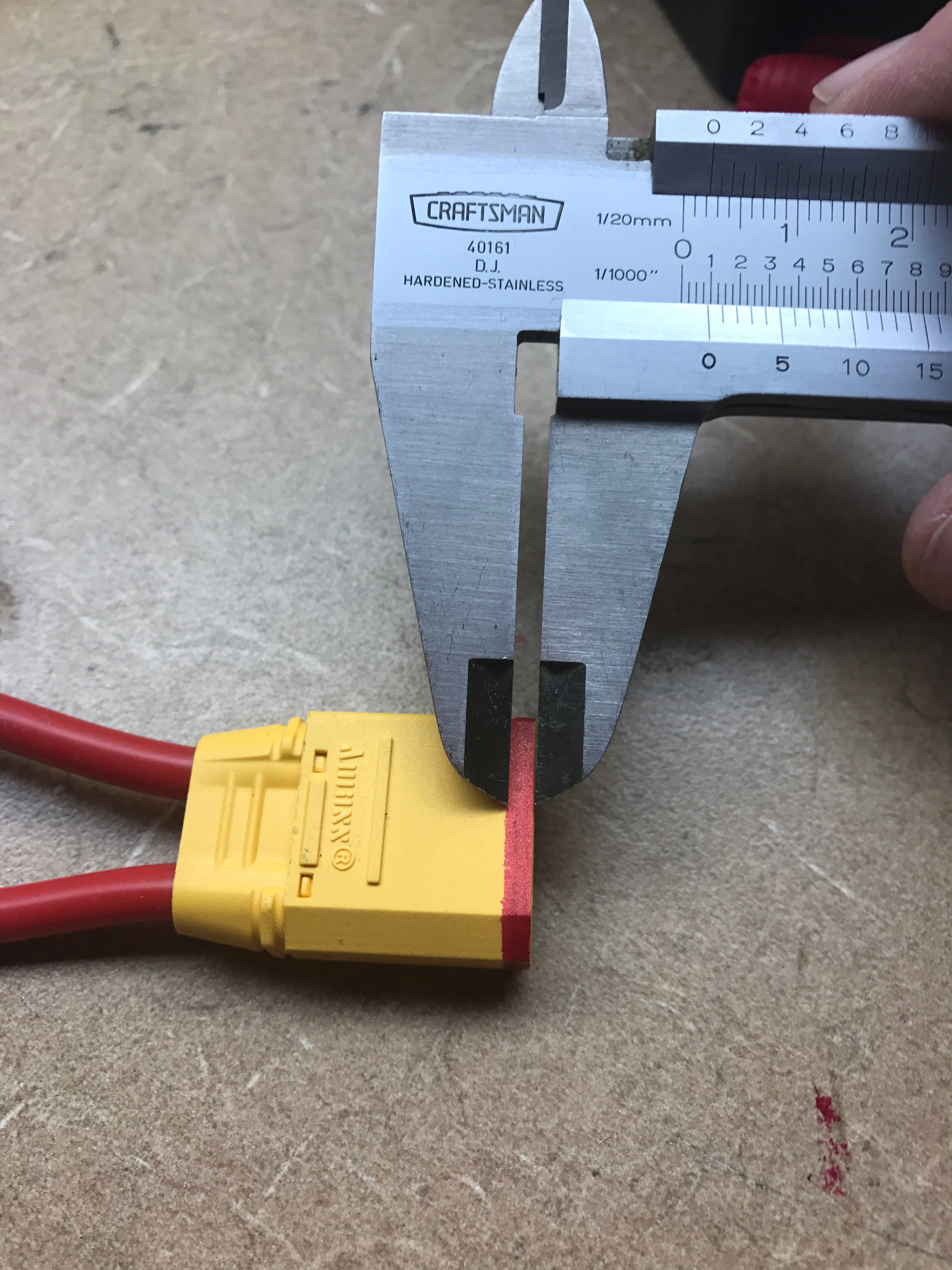
I must have had just enough coffee this AM. I think if I can cut off this much of the jumper's shield, the plugs inside will make contact even when held out more than 2mm.![]()
XT90 anti-spark....not sure if they're the best choice.
So apparently there is only about 2mm of contact distance on an XT90 Anti-spark plug...pretty bad. In these anti-spark units, there are 2 contact points, the first one near the outside has a little resistance to prevent the spark, and the second part of the contact near the back is fully connected. There is an insulator between. I bet the regular XT90s have more than 2x the contact area. Definitely the weak link in the power supply. Wonder if anyones written about this?
![]()
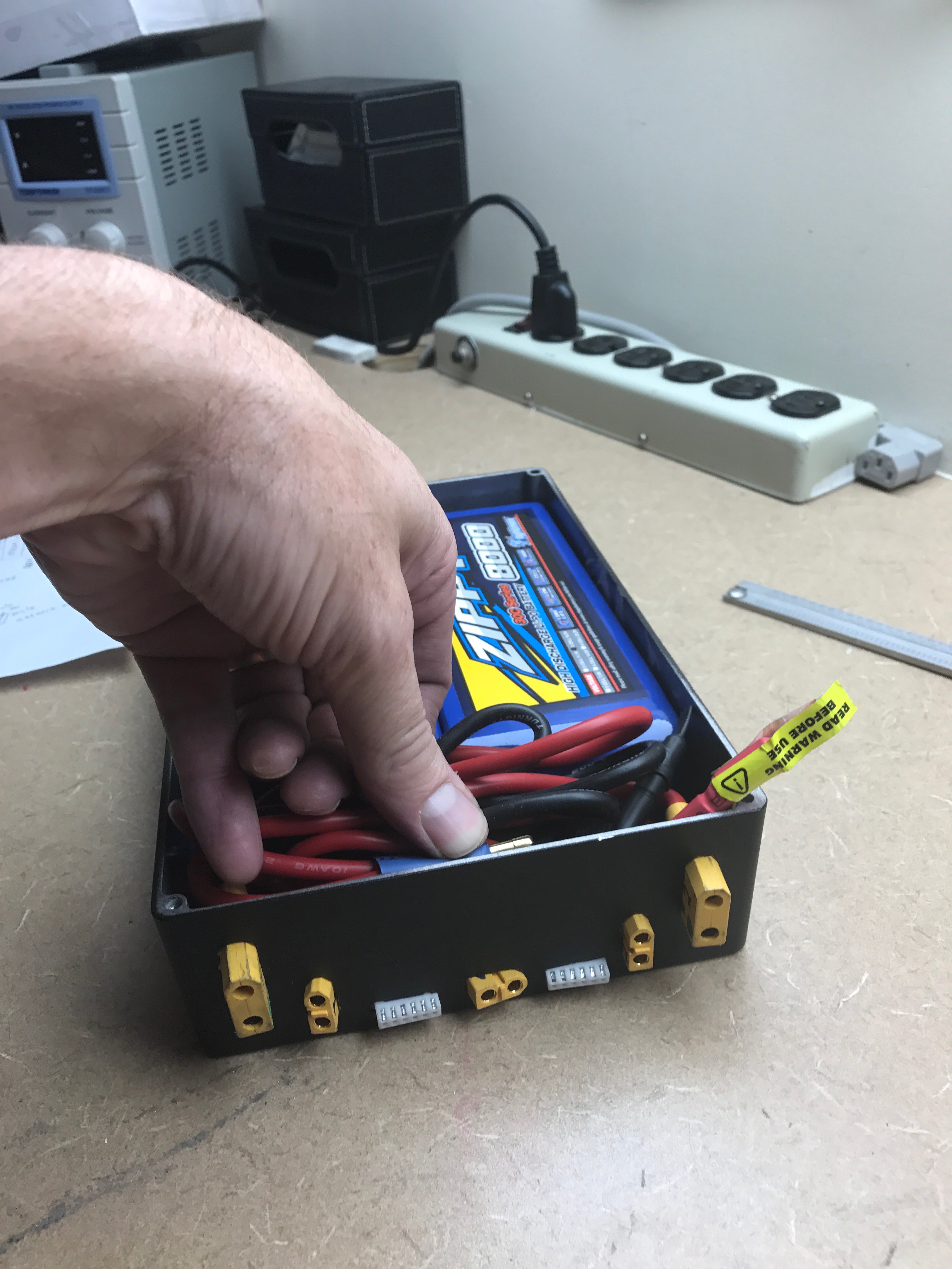
Hooked up and the wires fit...just barely.
Next step is sand, and epoxy everything in place, put labels on the various ports. I made the balance lead horizontal and moved to the bottom to make more room for the wires.
-
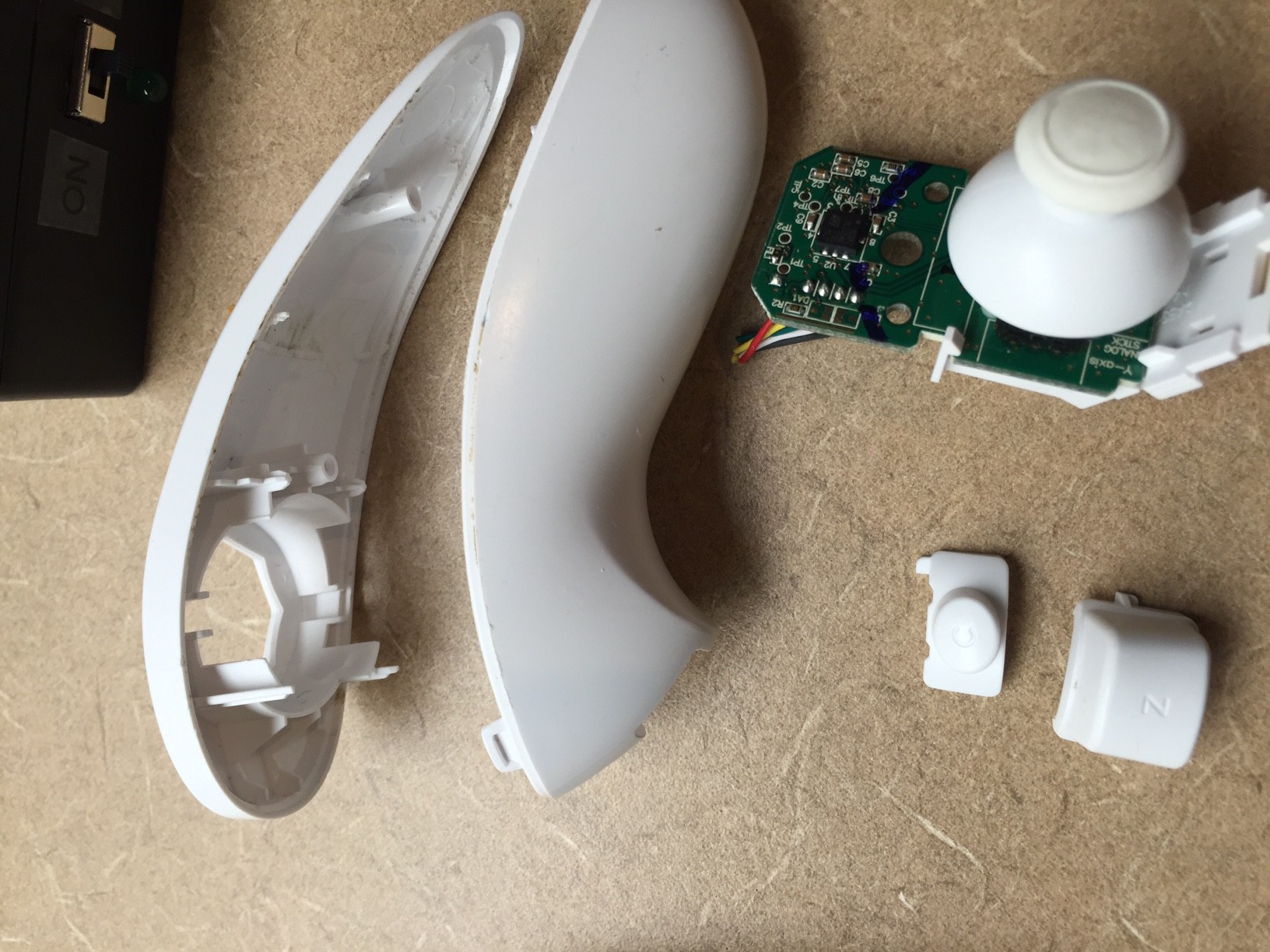
Wii-Mote Cut out...work in progress
10/09/2016 at 20:16 • 0 commentsEveryone seems to have this problem...we've tried a few things, have some ideas and next steps.
The Problem
The Wii-Mote cuts out at high power / high load like going up a steep hill but is otherwise a great controller. The VESC works best with the Wii-Mote interface/app because it has many controls for acceleration/braking. We already have a working NRF remote, but it's big and clunky and because it talks to the VESC via PWM, the controllability suffers. We'd really like to fix the Wii-Mote problem.
Background EMI & ESCs and cut-out.
Not all radios are able to successfully operate in the electrically noisy environment near an ESC (VESC). ESCs produce high voltage/currents and broadcast energy across a wide spectrum in very close proximity to radio antenna and the wires connecting to them. EMI (Electromagnetic Interference) can take several forms. 1) Radio EMI can affect over the air signal between the remote and the receiver. 2) Wire EMI can affect the I2C comms between the ESC and radio receiver. Radio interference can be mitigated by physically separating the radio from the ESC. However the longer wires need to create a separation increases the likelihood of degrading the I2C comms. At this time, it is not known which effect dominates the problem specifically for the Wii-Mote though our experience with the NRF2401 puts the blame squarely on radio EMI. There is also the potential that neither radio nor wire EMI is not the problem at all, and that either a low supply voltage from the LIPO batteries to the VESC is created under high load or that the VESC is not supplying a steady 3.3v supply to the wii-remote receiver.
What has been tried
We've already built an EMI tolerant remote using an NRF2401 connected to an Arudino Nano via I2C. The Arduino was then connected to the VESC via PWM/PPM. The wii-mote however is directly connected to the VESC using I2C. At first, the NRF implementation was also failing under high load. We fixed the problem by moving the receiver about 15cm from the VESC. This would suggest strongly that the NRF problem was dominated by radio related EMI, not wire EMI. Can we make this same assumption for the Wii-Mote? Maybe. The I2C comms between Arduino/NRF is not necessarily the same as VESC/WiiMote which may have different voltage drivers, pull-down resistors and ADCs, any one of which could impact noise tolerance.
Ways to determine what is happening.
Option 1: Sniffing the I2C bus may provide a clue. The I2C protocol to the Wii-Mote receiver is a very simple 6-Byte payload with 2 commands (init and send-data) so viewing and interpreting these packets on bench logic analyzer should be easy. However observing garbage data would not rule out either radio or wire related EMI. Bad data could be the result of either one. Observing "good data" on the other hand would be very interesting as this would point to something internal to the VESCs I2C ADC. Lastly, it would be difficult to even make this measurement with bench-top logic analyzers as the cut-out condition can only be repeated while riding under load or using a bench load which we don't have. We'd really love to have that actually.
Option 2: Move the Wii-Mote radio far (30 inches or more) from the ESC. If this works, the problem was clearly Radio EMI and no I2C EMI. If it doesn't work, it suggests I2C could still be the problem. It would be a good idea to provide battery power to radio during this experiment to isolate the experiment from any 3.3v power supply problem.
Option 3: (3.3v Power problem) I've added 300uF cap the receiver VCC/GND but it didn't resolve the problem. This really only rules out small power droops. A definitive test (that I have not done) would be supplying an independent battery supply. 2 or 2 AA batteries for example.
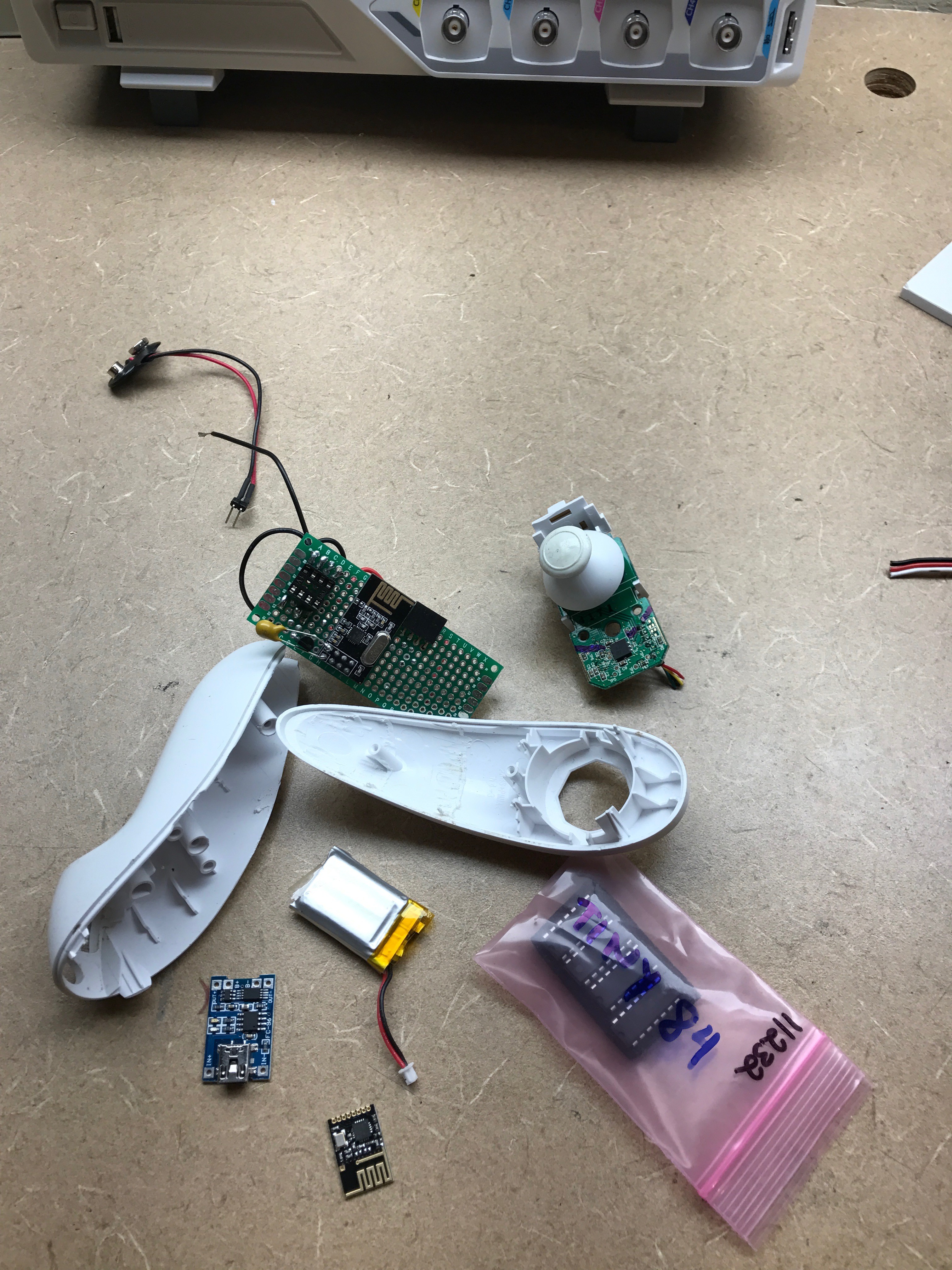
Option 4: Emulate Wii-Nunchk Remote I2C Slave. Convert our working NRF radio to emulate the Wii-Mote I2C slave protocol and connect via the VESC's Wii-Mote I2C port. This would take some time as I disassembled the hardware...pretty much all day. We might end up doing this...but not the first thing I'd try. The current remote is pretty big and square and not much fun to use. Long term, we want to finish our NRF/ATTINY84 remote that fits in a gutted out Wii-Mote, but we'll probably re-start that effort after the rains come in full force to the Oregon winter..
Option 5: A low main LIPO supply voltage problem. The VESC cutting out under load could be related to the LIPO power supply but some experiments show this to be unlikely. Lowering VESC low voltage cut off setting has no effect and fully charged batteries exhibit worse cutting out behavior. The latter suggests that the added energy of a fully charged battery contributes to EMI which decreasing the likelihood of low-voltage condition.
> I think we'll try Option 2 and 3 next (10/9/2016)
-
Battery Box Options
10/04/2016 at 18:51 • 0 commentsCustom 3-D Printed vs. Cast Aluminum Box
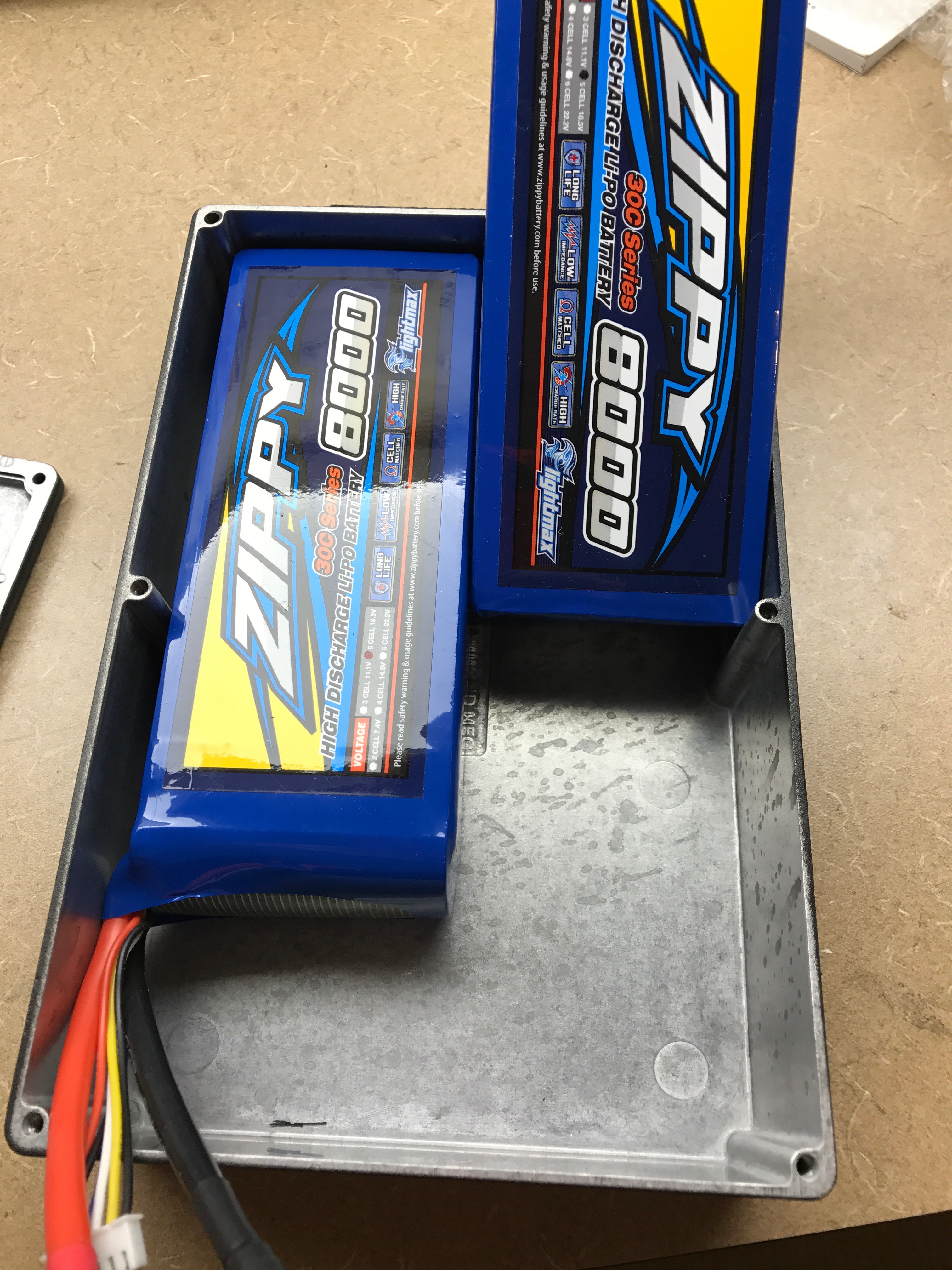
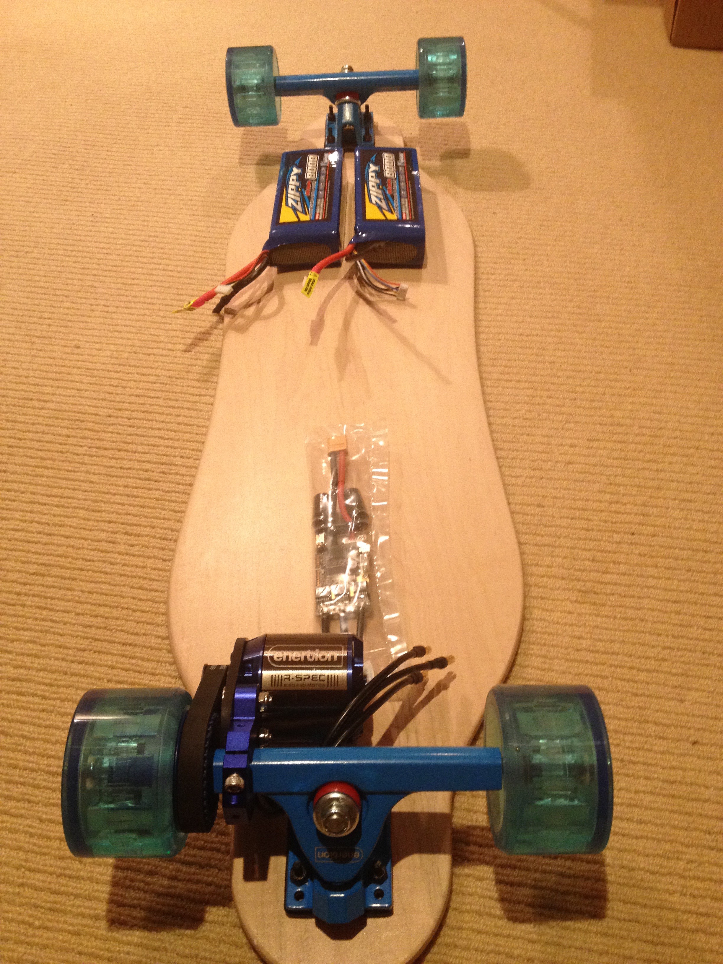
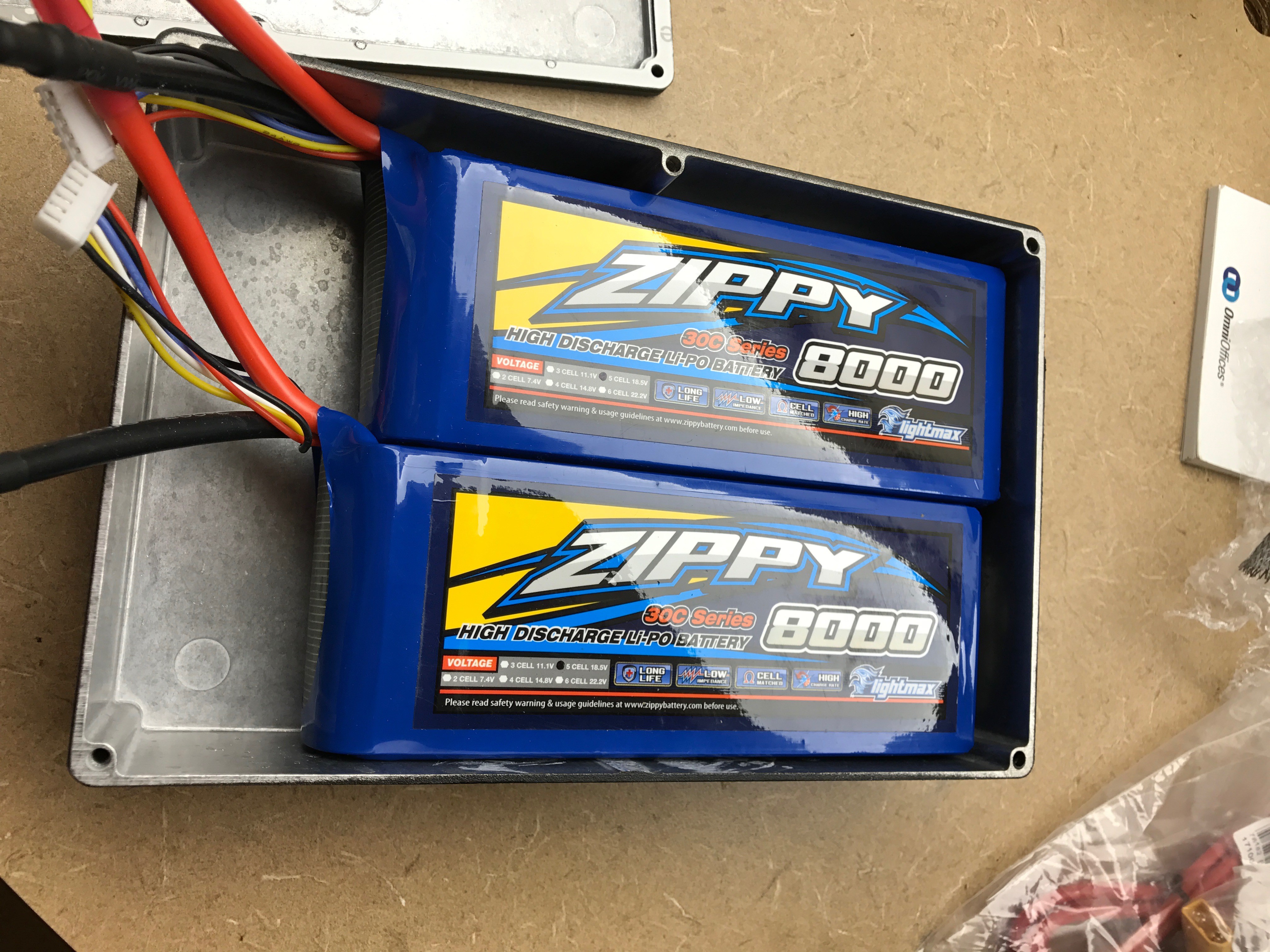
Batteries will be 2x8000 mAh 5s Zippy Lipo (170 x 69 x 44 ) in (In series for 10s)
The new board will be using the larger battery on the left
![]()
Option #1: 3-D Printed Box
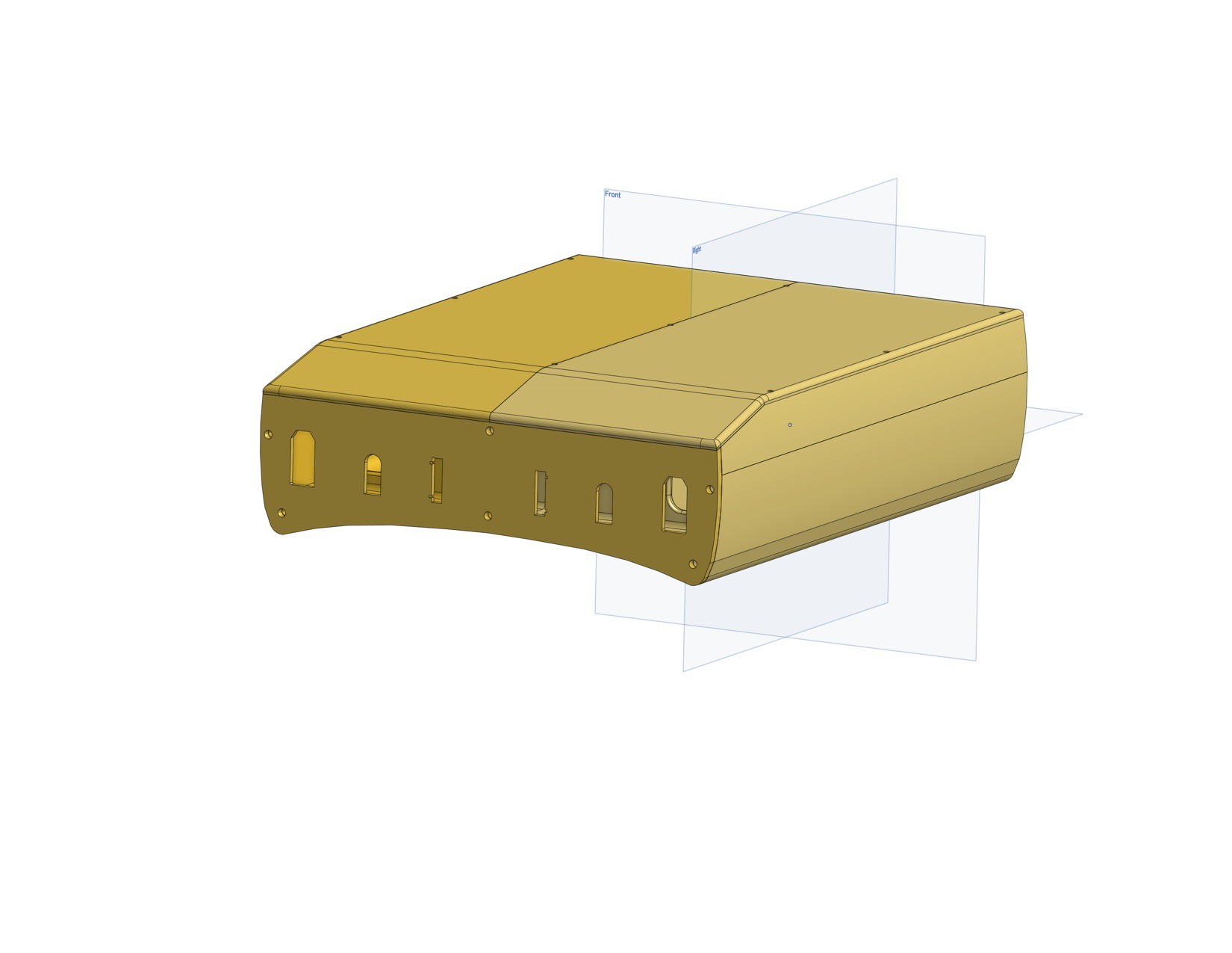
I completed this cad drawing but I haven't printed it yet. I'll update when I get "1st plastic" I created this in OnShape which is a great, free web-based 3d CAD pkg. Feel free to copy it for your own use, but you might want to wait to see how well this thing fits together. Onshape Link to CAD Drawing
There are 2 battery compartments that fix the 170x69x44 battery (+10mm space) and a 30x170mm space in the front compartment for wiring and placing the ports/adapters. The front face is ready for 2 XT-90s, 2 Xt-60s and 2 5s balance ports. It's about 3-5 mm thick depending on the part with added support on high-stress areas. (Wiring Schematic for wiring up 2 x 5s for independent balance charge, On/Off, hookup WIP) Overall Dimensions: 225 x 170 x 62 mm
![]()
The bottom (the side that touches the bottom of the longboard deck when this is flipped over) is curved 10mm @ 70mm from the center to accommodate our curved deck.
![]()
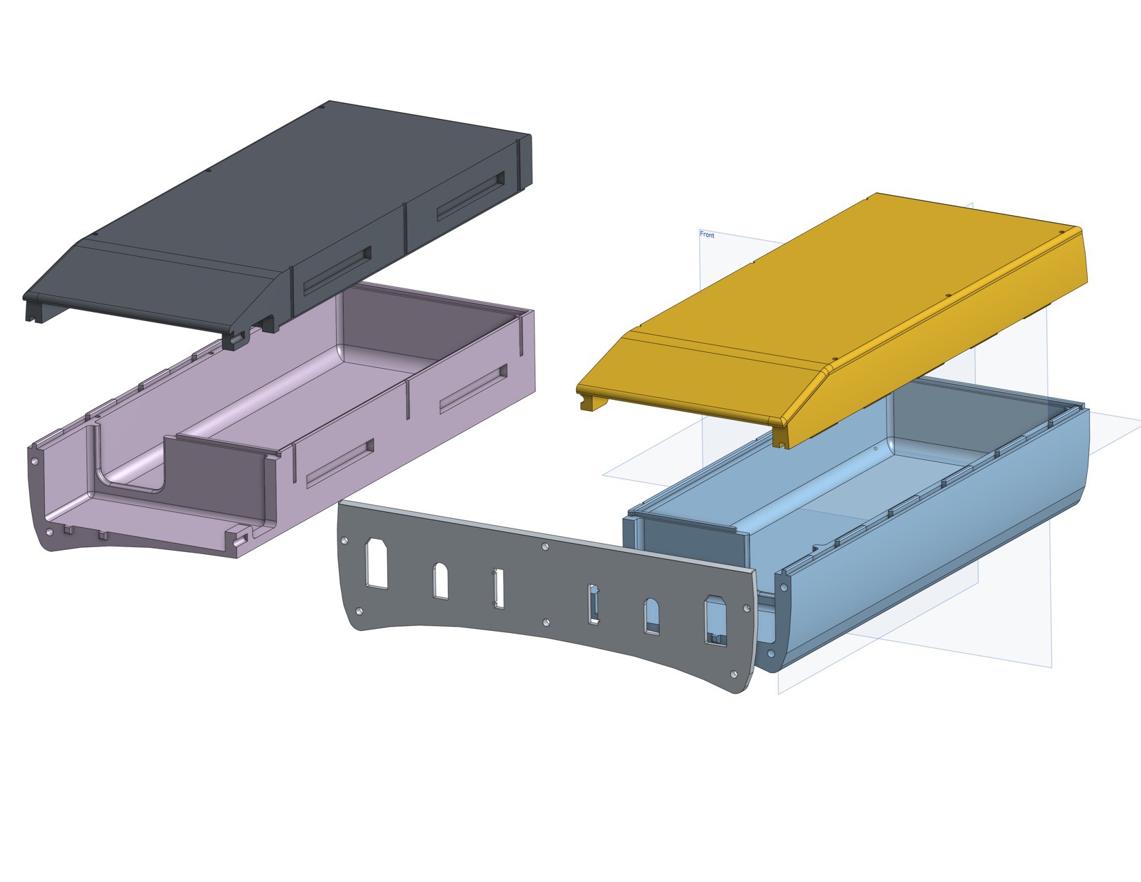
My nephew's printer can only make 215x70mm parts...not nearly big enough to create the top and bottom as single pieces. So we split the part into left/right halves. To help line them up for gluing, we added tabs/recesses. The top and front face are meant to come on and off so they attach withs screws. The model includes 3mm screw holes for self-taping screws. Ideally we could insert metal threaded sleeves (or nuts) to receive machine screws...haven't figured that one out yet. Honestly I have no idea how this is going to turn out. The print has to be fairly is precise, with no shrinkage, strong enough, etc to be a viable option.
![]()
This shows the profile of the 8000mAh battery in its enclosure.
Option #2 Cast Aluminum Box
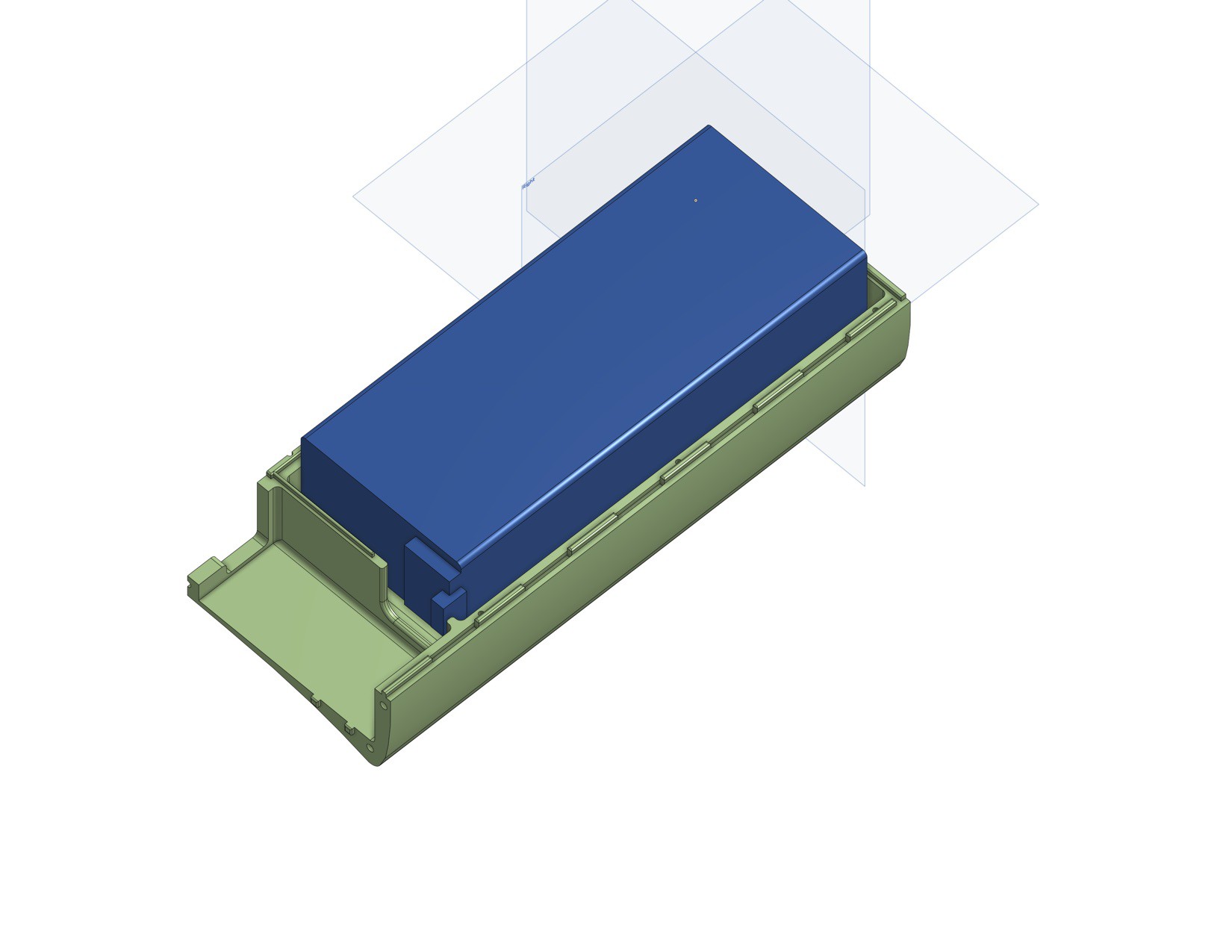
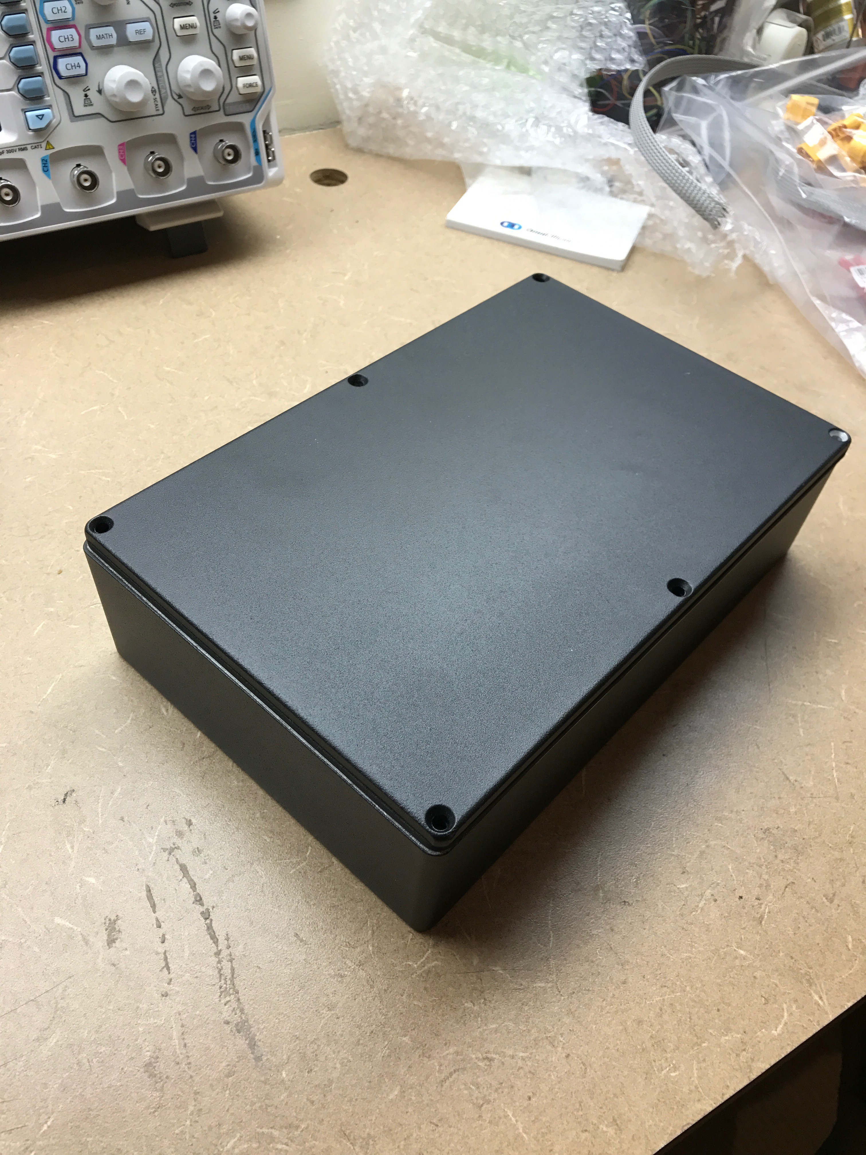
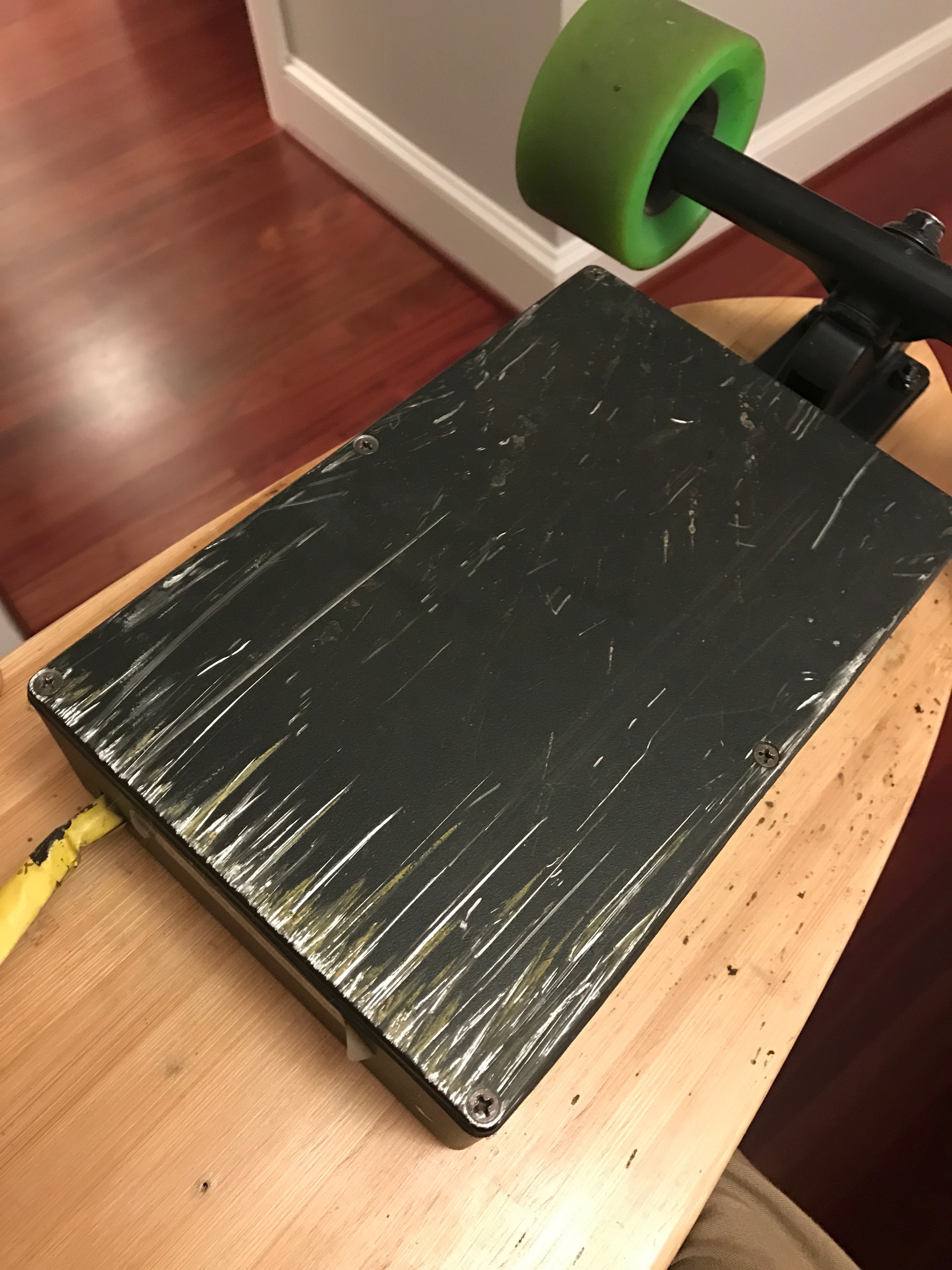
This box (From Mouser 1550WGBK) is JUST big enough to house these batteries (plus about 4cm of wiring space) but not a centimeter more in any dimension. It's the same one we've been using on board 1. The "W" in "WGBK" means water tight, which means it includes a rubber gasket. This is really important, not for water, but to keep the top from rattling loudly. The aluminum box is ready to go, much stronger and maybe more fire resistant than a 3D printed box. The only downside is that it's a bit heavier and square looking. We mount it with small rubber bushings to suppress vibration/rattle around 4 screws drilled through the bottom.
![]()
Still...a few speed bumps manage to strike the edge of the box of our current board. This is one reason the 3-D printed box would be angled at the edge.
![]()
Batteries almost fit.
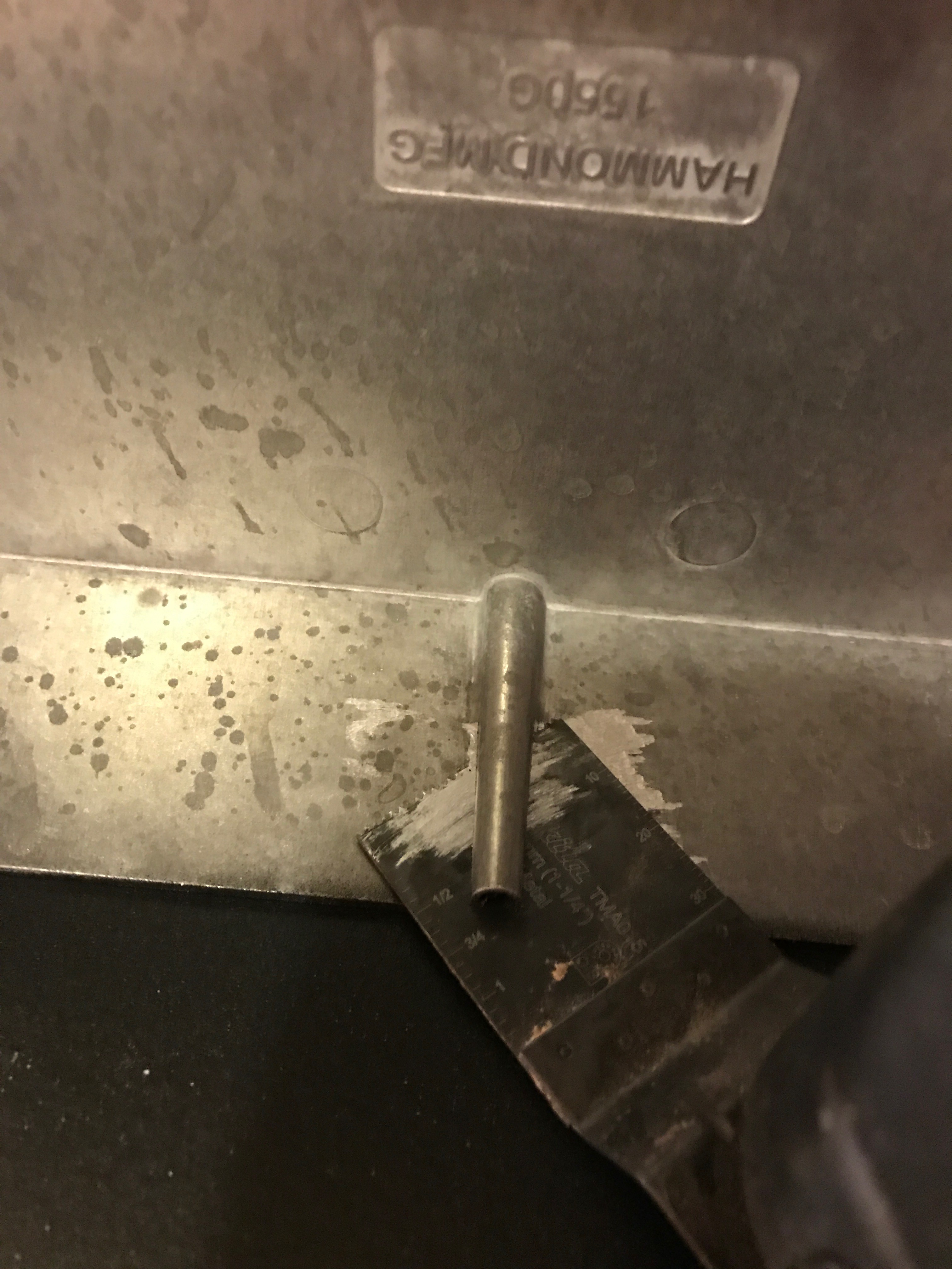
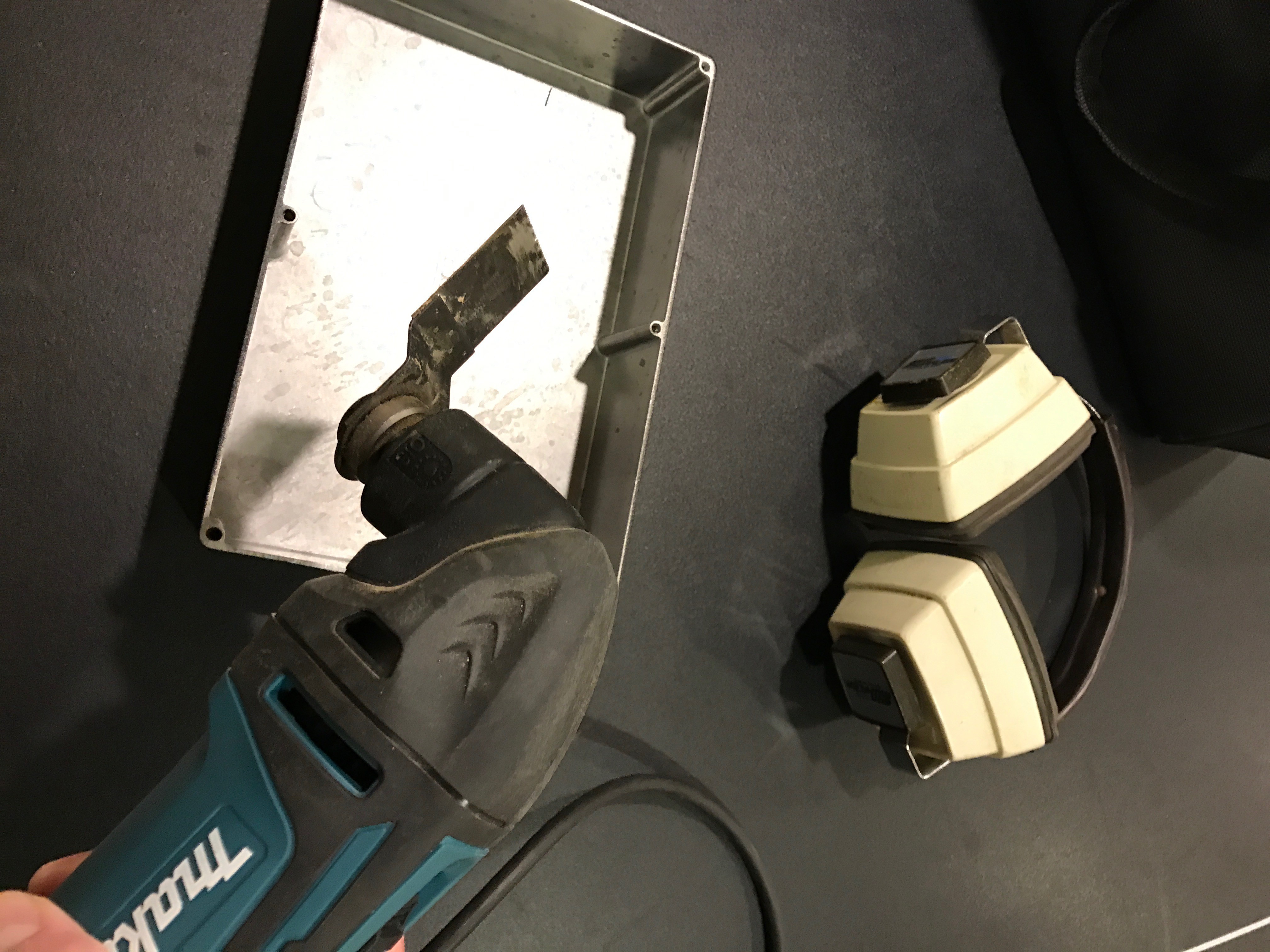
Need to take out at least one of these screw posts.
![]()
Plunge cutter
...and this already was my favorite tool.
![]()
![]()
![]()
Snug, but good fit. We might take out that second center post to make a bit more room for the batteries and padding. Still, be nice to have that middle screw in there to keep it from rattling.
![]()
-
Second E-Longboard in the works
10/02/2016 at 22:40 • 0 commentsWork in progress. After 6 months a few hundred miles...ready to put all our improvement ideas to the test on our next board. It will be great having 2 boards and be able to ride together with the boys.
![]()
Here is what we're doing differently:
Trucks/Mount: Enertion: I absolutely love their mount we're now using on our current board because it just stays in place. I did several logs on this topic already. The rear mount can be a big source of trouble if it's not rock solid. My hat is off to guys who can weld their own mount. I looked into it and for the money and time, I'm happy to farm this one out and go buy the part.
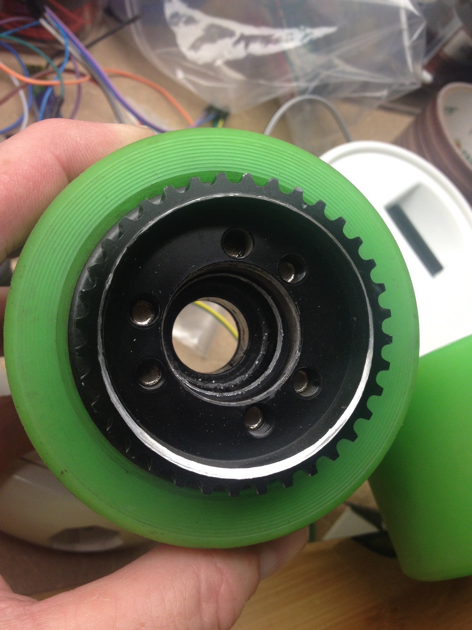
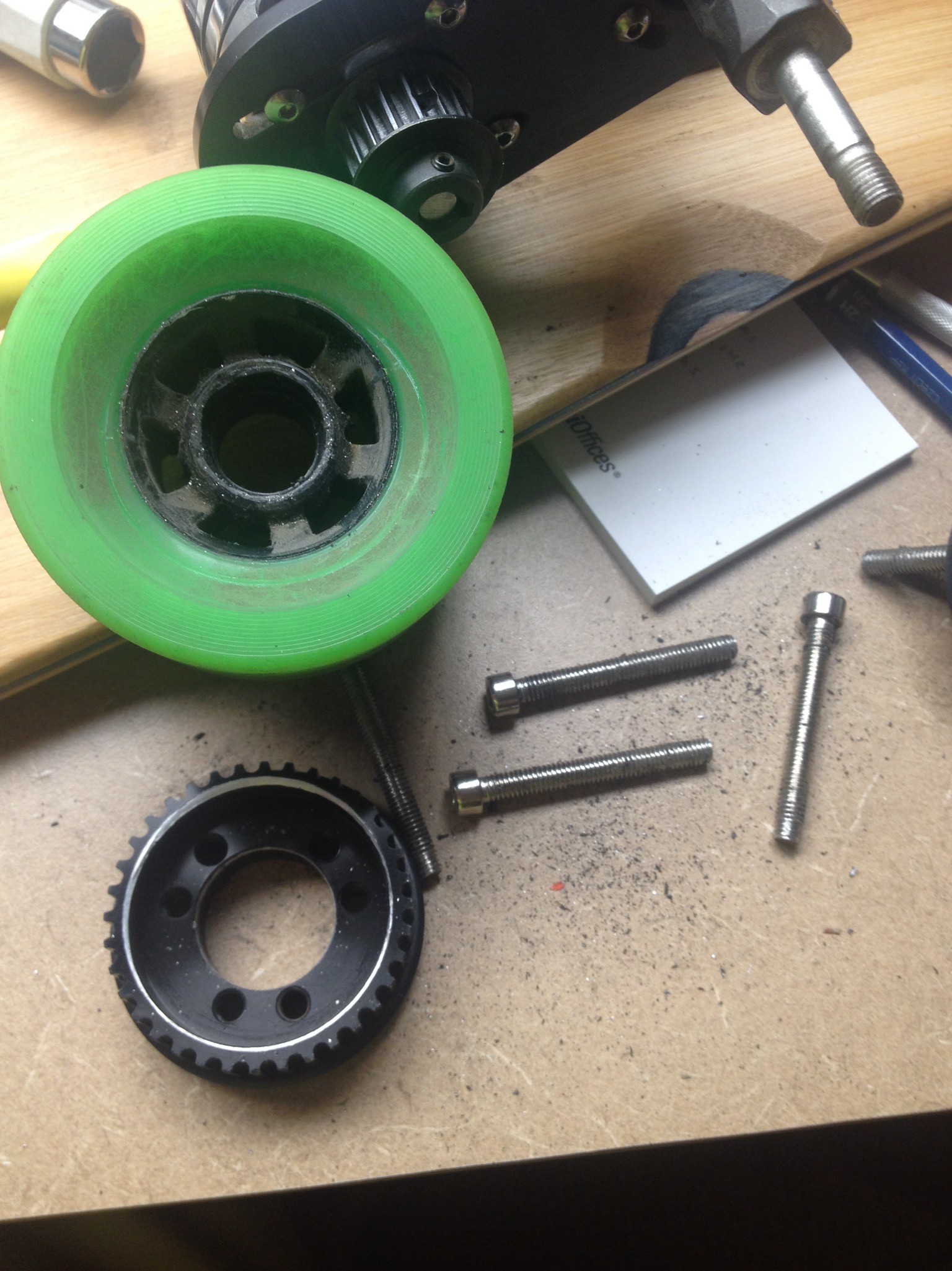
Rear Sprocket/Wheels: Again Enertion. The one-piece nylon rear wheel sprocket is well fitted to their wheels and IMO gives you a better result in terms of alignment and sprocket location than the "through-bolt" kind. If you use the Enertion rear-sprocket, I think you will also need to use their trucks. The half-round profile shape is pretty common but, they seem to have an extra long shaft (adds the width of a truck spacer to accommodate the sprocket). Don't know for sure though...maybe you can buy trucks elsewhere with the same profile and extended shaft.
Motor: Enertion 190KV. I like our current 147kv Turnigy motor. However, it has a smooth shaft so mounting the front sprocket required grinding down 4 flat spots for set-screws. Occasionally these needed adjusting even with lock-tight. With a 175 lb rider whacking between forward and brake, those little set scews can take a beating, especially if the motor shaft grinding isn't flat. On the other hand, the enertion motor, while a bit more expensive, has a very nice key/tab thingy in the shaft that makes a perfect union between the shaft and sprocket. The sprocket is held in place with 2 small retaining rings...no set screws. They really did a nice job here. A very tight fit you need to tap in place gently with a hammer. A bit more $ but I think worth it. Happy we made this change. It's more KV: 190 vs 147 so we'll get more top-end speed. Gearing is higher too 16/36 vs 12/36. Not worried about low-end torque because we're bumping up the voltage from 6s to 10s, and 20C to 30C.
![]()
Battery: 2x 8000 mAH 30C in series for a 10s. We'll have about 2x the range and power. I'll probably post our new power schematic. Haven't wired it up yet, but the idea is to be able to independently balance charge 2 5s batteries that when being used (not being charged) are connected in series...and NOT have to open up/unplug the battery case. I've read the VESC likes the 10s setup and may have reliability problems at 12s.
Single Motor. Staying with single wheel for now. There are definitely times I wish I had a dual motor but we're just learning to ride and it hasn't been a big deal yet. Mostly you notice it loosing traction in very steep up/dn hills and when powering out of tight left turns. (motor is on right-rear). If I start commuting to work on this thing, I'll invest the the extra $350 bucks (additional VESC/Motor/Mount/Sprocket)
Deck: We like having the kicktail on our current board, but just for a change of pace, we're trying this one that has kind of a boosted-board look. The lamiate is really flexible...very bouncy. Haven't ridden it yet, should be interesting. http://www.customskateboards.com/Custom-Longboards/Freeride-Longboard
-
Remote Refinements
10/02/2016 at 21:49 • 0 commentsNow we have a few hundred miles on our board. We ride almost every day. Finally put some anti-skid down. Carved out the design and painted the board green under that spot. We've ridden so much the drive wheel is 1.5mm smaller than the others...might be time to rotate the wheels.
![]()
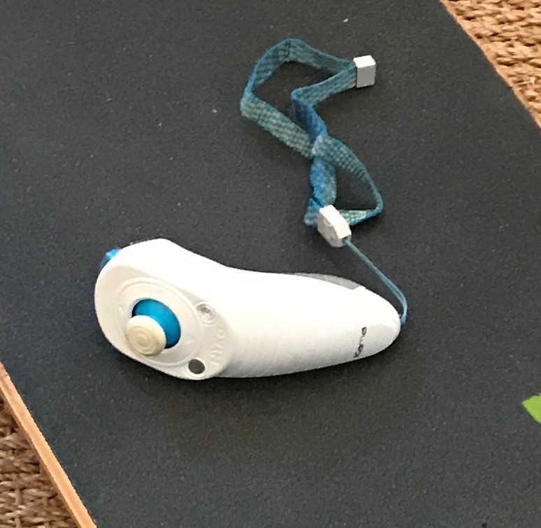
Still working on putting the NRF based remote inside a Wii Nunchuck case. Took a while for a bunch of parts to arrive from China. USB-3.3v power/battery management PCB, LIPO, Smaller NRF package, switches etc. ATTINY85 has been tricky. Many nights staying up past 3:00 AM debugging the ATTNIY/NRF interface. Debugging options are pretty thin. There is a new NRF2.0 chip that just came out...has it's own micro inside...might be a better option. More homework.
![]()
Nyko Kama Experience (good and bad)
While working on our own nunchuck, we switched from our clunky, home-made NRF remote, to an off-the-shelf Nyko Kama wireless nunchuck+receiver a few months ago. Here is what we learned.
![]()
The Good - Acceleration: The biggest improvement over our home-made remote is that the VESC is now managing acceleration/deceleration via the nunchuck 'app' rather than the ppm/pwm logic on our remote control. IMO there is no comparison. The VESC knows the wheel speed, so when accelerating after coasting, the throttle response and added torque is instantaneous. Just no way to implement this feature on the remote control because you need the wheel speed information to program this behavior. The Wii remote is light and feels good, battery life on 2 AAA has been great, the thumbstick is smooth and very easy to control.
The Bad - Cut out: Like many others seem to have experienced, this remote cuts out under high load..ie goosing the throttle going up a hill, the VESC with shut down and resets after about 2 seconds. Really sucks. Still haven't figured it out. Some popular theories are
1) 3.3v power drop to the receiver chip (update: 10/3 probably no)
2) RF interference from the high-current VESC
3) Vesc performing a low Voltage drop cutoff.
4) Some other VESC software issue.
As far as I can tell, the community is still guessing the cause...and no one has found a solution. Like others, I managed to get some improvement by shortening the wires between the VESC and the receiver, and moving the DC/AC power wires away as much as possible. But given the geometry of the VESC there is only so much spacing you can do. I'm planning on building a telemetry setup using arduino and a data logging chip...more parts from China...so we can definitively answer this. I'd ike to plot throttle position, speed, Battery voltage, 3-phase voltage, voltage to the remote.
Final Conclusion: Wii-Mote is OK...not a final solution. Using the VESC's nunchuck app really raised the bar for performance over any remote control using the PWM input. Our next NRF remote...any remote...will absoltely have to use the nunchuck input protocol.
(Update: 10/3/2016
I added two 147uF capacitors to the Wii-Mote receiver VCC/GND last night but no improvement to the cut-out problem. Unless the supply voltage goes completely to zero (which I doubt), these should provide 1-3 seconds of current in a typical transient low-voltage situation. ( 1v drop * 294uF ~= .300C . 100mA draw (a total guess). 1v drop = 3 seconds, 2v drop is about 1.5 seconds to discharge the cap)
VESC Timeout feature recommendation
The VESC allows for setting a single value for braking force to be used in the event of a remote control time-out...ie if the remote battery dies. Better than nothing, but ideally it would implement a ramping break that would start small but progressively go to MAX breaking over say 5 seconds. If the remote cuts out on level ground, you are fine as is. But if a remote failure happens while going downhill...or approaching traffic...you are pretty much hosed. You don't want to set a single high value either because if you're not ready for it, max breaking will toss you off the board.
-
VESC Finally Arrived
07/25/2016 at 01:32 • 0 commentsVESC
From Enertion for around $100.00 After about 50 miles using our original Turnig 60A ESC (obviously with no brakes) our VESC finally arrived! Super excited to hook this up.
![]()
Installation
Installation was pretty straight forward. We added the female 4mm bullet connectors (because 4mm male connectors were already on the motor's wires), and hooked up the 3 wires to our arduino/NRF receiver. With the Caps, the VESC is a bit longer than most ESCs, but just fit in the battery box. It has no heat sink...not sure yet what (if anything) to do about that.
Setup
Without any setting changes, the motor was completely unresponsive. Poking around esk8 forums and playing around with the software, we finally got the many settings in line with our 6s battery * 147kv motor setup, adjusted the amperage for discharge and charge (braking), etc. I think the original VESC settings were set for Enertion's 10s battery, 190kv setup. All told, the setup took a bit of patience, a few hours and about 5 iterations (test runs) to get it right. There is very little in the way of documentation so some of the field/value pairs are a mystery. Best source of info are the message boards on esk8.
Setup Speed Control: I initially thought something was wrong with the VESC's ability control motor speed based on throttle position because sitting on my bench, I could only get full stop or full power...not much in between. It clearly displayed the joystick position so we knew it wasn't the the PPM/PWM settings. But I think this is normal for a current-controlled system...and with no resistance on the motor, even a small current will quickly spool up to max RPM. After a quick road test (under load now), acceleration management was ok.
FOC: We're using the new FOC mode...supposed to be super quiet and allow starts from a full stop...no pushing needed. It's a few MPH slower using FOC (vs BLDC)...not sure why.
PPM/PWM
VESC calls it PPM but I think they mean PWM. They are totally different things, but our arduino-based PWM output seems to work perfectly when selecting the PPM mode in the BLDC tool.
Initial Testing
Steep-Hill Torque: Noticeably less torque up our street's very steep hill. I suspect the old ESC was able to drag more current than the battery's 52A rating and the VESC holding to the 52A setting. Might also be related to slow-speed torque in FOC mode? Not sure yet. Getting plenty of acceleration torque on flat and medium hills when the motor is turning faster.
Acceleration: From a standstill the acceleration is pretty brisk...took some getting used to but now we love it. No power lag coming out of a turn or hitting the gas after coasting...instant power. Fun.
Braking: After 50 miles of using our hobby king ESC with no brakes...we really appreciate this feature now. We're able to go down hills, stop in traffic,...again, just awesome. Went on a 8 mile ride in high density traffic today on the water front in Portland and were able to weave in and out of people, slow down at will, stop at traffic lights, stay at a reasonable speed going downhill on the Tillikum Crossing bridge with people everywhere.
Quiet: Amazingly quiet...in FOC mode. Practically zero engine noise...a huge difference.
Starting from a dead stop: I'm so used to pushing a few times that it's hard to get out the habit...but from a dead stop it will go with absolutely no jitter or engine whine. Completely silent.
What we'd do differently next time.
Motor Shaft/Sprocket: Our 147KV Turnigy is nice, but because the shaft is smooth we had to file flat spots for the sprocket's set screws. This was fine with a normal ESC. Never had an issue with the sprocket moving after we cranked down on the set screws. But now that we're braking, the back and forth force is loosening the sprocket. Probably going to pay a bit more for Enertion's 190KV motor that has a recess in the shaft for a king-pin.
Battery: Currently we have 2 6s batteries we run independently. Good setup for learning, goes about 12-15MPH. Plenty fast, good acceleration and great for learning. We'll probably go with a 10s setup (2 5s in series) for a bit more top-end speed and acceleration.
Trucks/Wheels/Hardware: Enertion single motor setup (the big one). Looking for a maintenance free engine mount that stays in place. Hope that fits the bill.
Deck: Actually we'll probably not change this...love the 40 inch length, and 9 inch width...and especially the kick tail....not for tricks but for turning the board around when stopped, 180 or 90 changes in direction.
-
Man down
07/19/2016 at 17:54 • 0 commentsWheel fell off during a ride
Luckily I wasn't going fast or this could have really sucked. Bearing failed on the drive wheel and the wheel fell off...nut still attached.. Anyway, we think we know the story of what happened.
What happened.
- The mount will not fully tighten...and wiggles a bit no matter how hard you crank down on the nut.
- Mount at some point made contact with the rear sprocket and made aluminum shavings.
- Shavings get in the bearings.
- Bearing fails
- Wheel falls off
Some pictures of the carnage.
Bearing toast.
![]()
This is where the rear sprocket was making contact with the mount. You can see where it's been worn down (silver ring). You might notice the wear pattern is a bit non-symmetrical...more wear on one side of the sprocket. This shows how the sprocket is not perfectly aligned to the wheel. I've made a previous log about this problem, but this is best I can align the them.
![]()
Lots of aluminum powder came out of the wheel hub when I took off the sprocket.
![]()
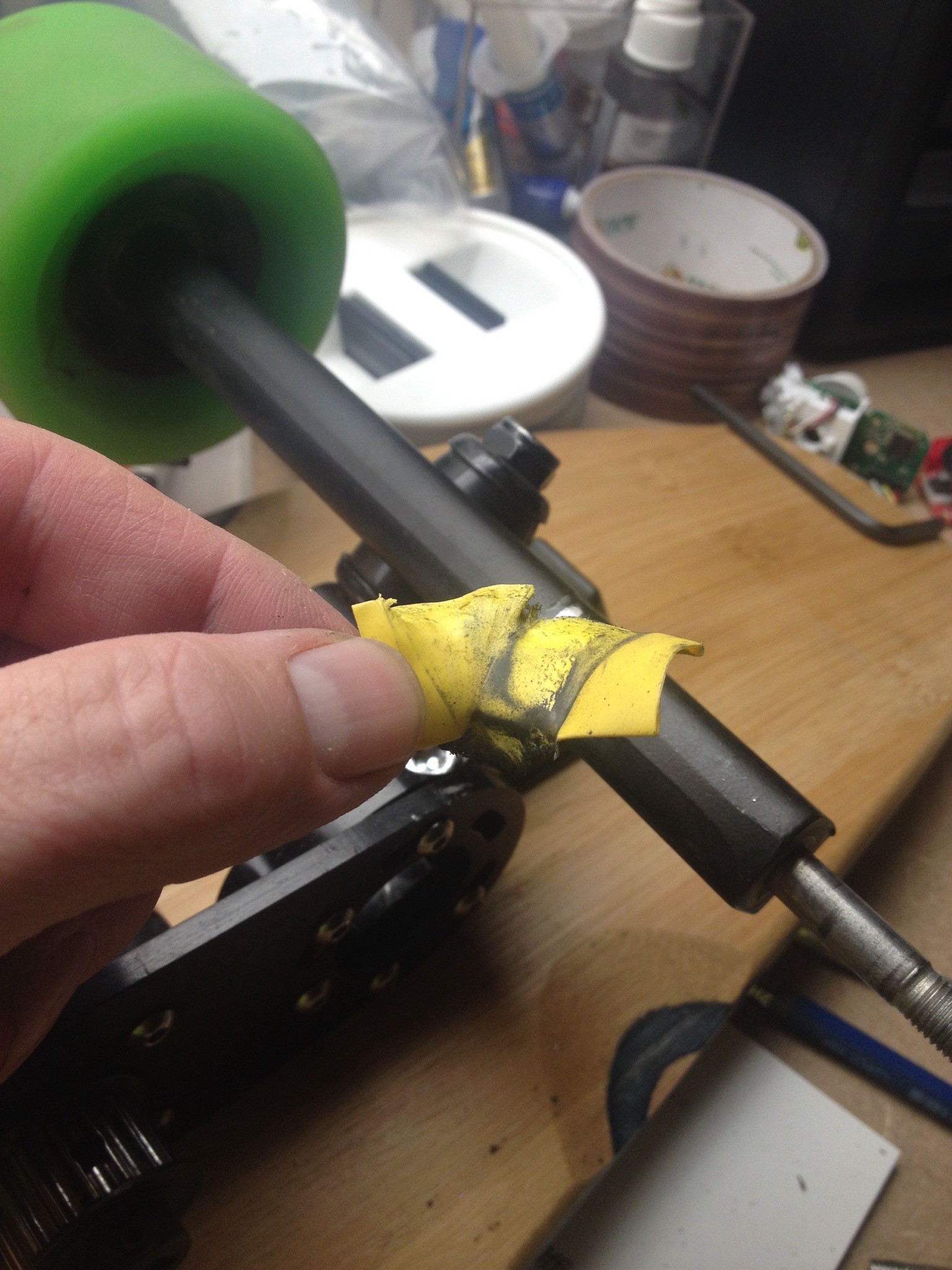
![]()
After about 5-8 miles, the heat shrink is pretty much toast from the slight wiggle in the mount-trunk union. Just can't get a perfect, permanent fit. Heat shrink probably isn't the best material for this...sucks actually.
![]()
Conclusions:
So this is our first "test" board. We plan on making 3...one for me and 2 more for the boys. It's been a really great learning process and we've had lots of fun. What's next?
- This motor mount just can't be made to have a permanent fit...requires constant adjustment after each ride. Doesn't matter what material you use to improve the gap. Tried everything including aluminum shims.
- Rear wheel sprocket setup is OK...so far hasn't needed much adjustment after getting it fit
- We'll be trying the Enertion setup next time.
-
NRF and Attiny not playing well together
07/11/2016 at 23:21 • 0 commentsCan't go Nunchuck until the NRF and ATTINY play nice.
Our current NRF and Arduino Nano-based remote works well, but is big and clunky.
![]()
Before we can make a nice one inside a wiimote, we'll need to get the smaller and lower power ATTINY85 (or the larger ATTINY84 with more IO pins) working.
![]()
ATTINY / NRF is not working for us. We're trying everything we found online, including...
- Using the same NRF libraries and code that work for others
- Everything wired up correctly
- Using nice wires with good terminals, no jumper wires, no shorts or opens.
- Good power supply to both the Tiny and NRF
- Using plenty of power caps, 100uF, 10uF .1 uF. Not seeing any power droop, see good signal transistions.
- Attend is supposed to be running at 8mHz
How do you know the Attiny's 8 mHz clock is working?
Run a simple blink sketch with a 1000ms delay using "Tools->Clock->8mHz" If the LED blinks every second, then the Tiny Clock is working at 8Mhz. If on the other hand, the LED blinks for 8 second and off for 8 seconds, then it is still running at 1mHz.
void loop() {
// put your main code here, to run repeatedly:
delay(1000);
digitalWrite(3,HIGH);
delay(1000);
digitalWrite(3,LOW);
}
To fix this...Burn Bootloader?
From Arduino IDE simply selecting "Tools->Clock->8mHz" tells the chip what the clock frequency is supposed to be so that things like timers still work. For example calling delay(1000) actually takes 1 second. But selecting 8mHz from the menu doesn't actually change the clock frequency! Turns out that to actually change the ATTINY clock frequency you have to use an Arduino as an ISP and select: "Tools->Burn Bootloader". This sets the ATTINY fuses to actually speed up the clock. Running the above blink program should yield 1-second blinks.
Confirmed @8Mhz...but still not working.
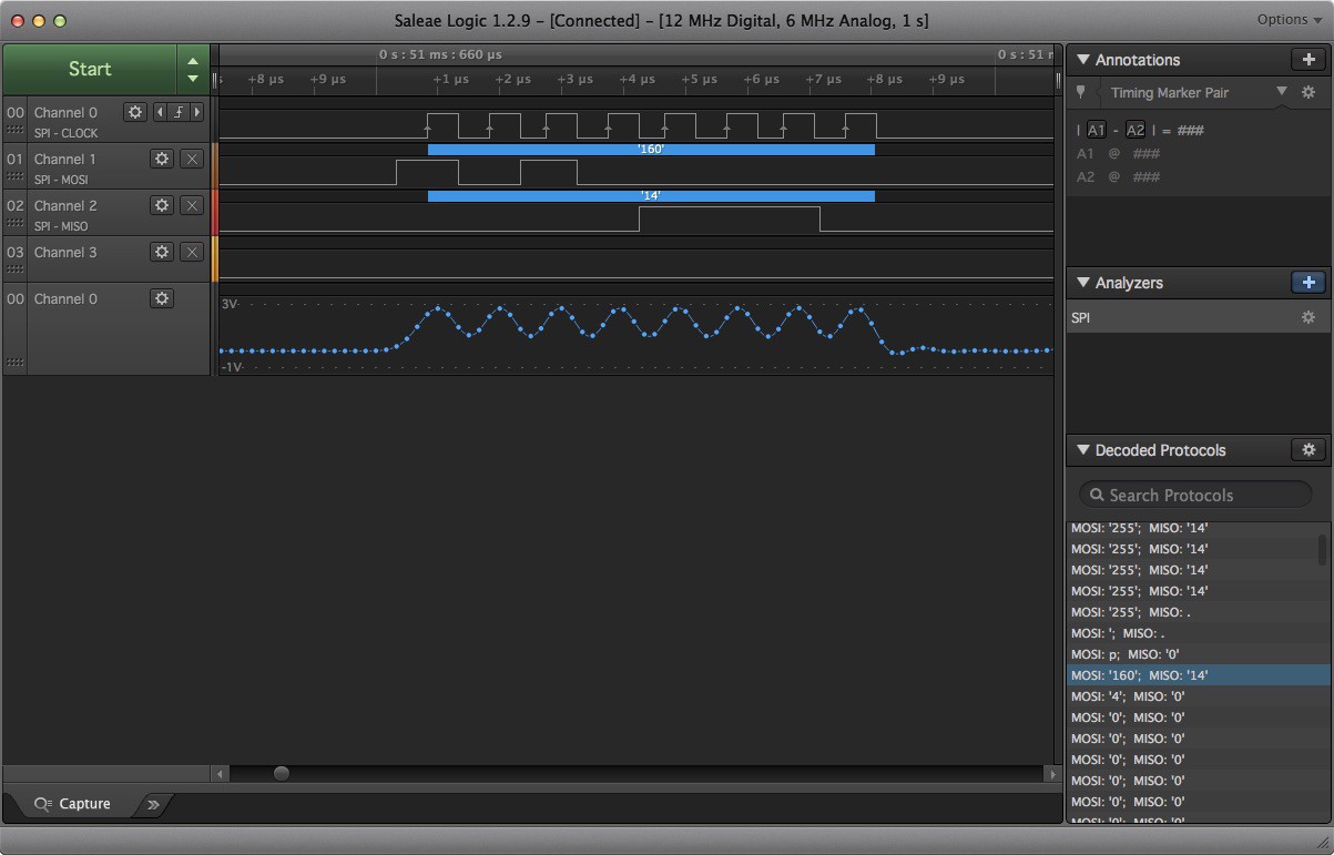
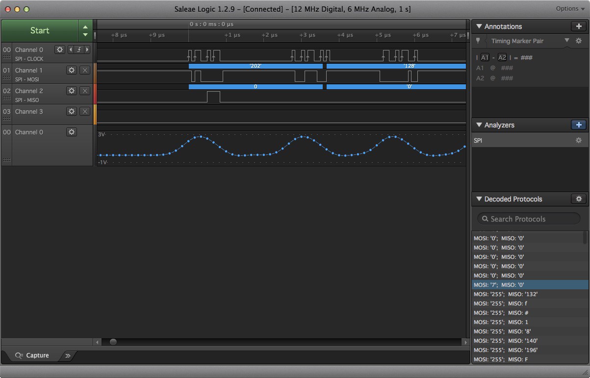
We're seeing a difference on the SPI Logic Analyzer between the Attiny and Arduino implementation. The numbers being passed are completely different and the SCK frequency is 4x slower with the ATTINY. The SPI protocol has the "master" control the SCK so that shouldn't be a problem...interesting though.
The following logic analyzer output (top row digital and again on the bottom row in analog) is showing a 1 mHz SCK frequency for the ATTINY and NRF combination.
The following logic analyzer output is showing a 4 mHz SCK frequency for the Arduino and NRF combination. Interesting how the clock is now too fast for the Saleae's relatively slow ADC to pick up the transitions. (the bottom row doesn't match the top).![]()
![]()
Serial Print on ATTINY
We're not taking advantage of this...mainly because all the pins are taken up by the NRF. Not sure, but maybe we can get software Serial.Print working on the ATTINY84 (which has many more IO pins)
-
NRF2401 Power Capacitor Experiment
07/01/2016 at 16:21 • 0 commentsQuick aside: Prototyping with crappy jumper wires is bad. By accident we discovered our entire NRF-problem was caused by our combination of female-female and male-female jumpers. We're investing in a better supply of wires with all combinations of terminations.
Probing the power and SCK lines
The NRF is thought to brown-out occasionally and/or the signal transitions are too slow to be detected unless you put a 10uF capacitor across the VCC/GND pins of the NRF. Don't want to go into too much detail here, but what we were hoping to see when we probed the power and signal lines is 1) Constant voltage on the power supply that never drops below 3v and 2) crisp, quick (i.e. vertical) transitions for the signals.
Results
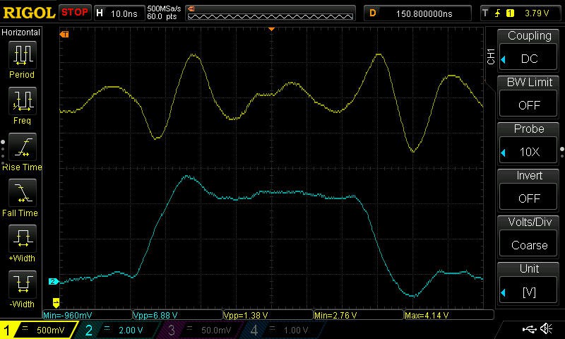
![]()
Above is a snapshot of the POWER (yellow) and SCK (blue) lines. At this time, there is a single 10uF tantalum cap across the NRF2401 power/gnd pins. As the SCK transitions from low to hi, the power drops significantly (to 2.76v) and the clock rise/fall slope is pretty bad. Pretty nasty looking: big droopy power and slow SCK transitions. We think the NRF is just barely operating...almost browning out and at the very margins of signal integrity.
![]()
Next we tried these NRF2401 with an NRF breakout board (above) with no external capacitor. This PCB has its own on-board power supply (5v to 3.3v) and surface mount capacitors of unknown value. However in testing, the power supply and on-board caps seemed completely inadequate to supply steady current to the NRF and absolutely needed the extra 10uF capacitor to work.
![]()
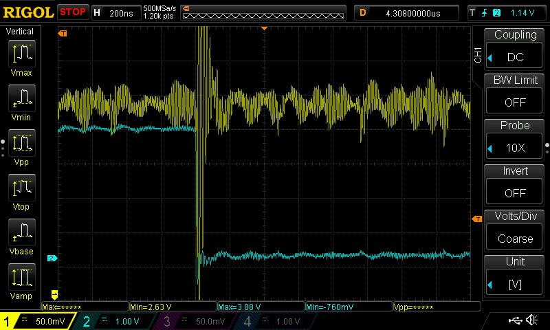
Next, we swapped out the 10uf Cap for a big 100uF. Above we see the large, slow power droops are much improved, but now we still see these little rapid, sharp power droops. This is probably because the 100uF cap is too slow to supply current for sudden bursts in load.
![]()
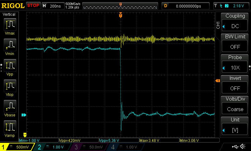
Finally we added 2 more smaller caps to handle these quick power loads: 100uF Tantalum, 10uF electrolytic, 0.1uf Ceramic. Pretty clear the NRF2401 needs a little babysitting on the power supply because finally the power signal and SCK lines look pretty good: very little power droop and sharp transitions on the signals. This was a fun exercise and let us play around with a lot of the features of our new Rigol toy. So again, the single 10uF still works but maybe the 3-cap setup might help somewhat when battery power is on the low side....another experiment?
![]()
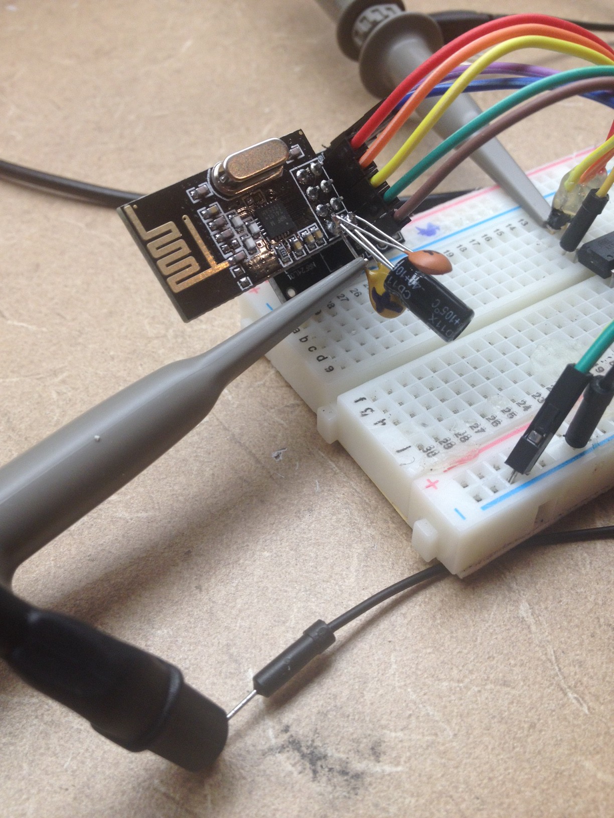
Here is the NRF, NRF break out and the 3 capacitors.
Taking directly to the NRFWe found the following code to return the status of the NRF unit. It was nice to directly read the status in detail rather than simply not receiving a message on the receiver.
RF24 myRadio(7,8);

void setup() {
...
// provides a way for print to link to Serial.println
fdevopen( &my_putc, 0);
// public method in NRF library that prints lots of setting details.
// should not be all 0x00 for example..should have real data.
myRadio.printDetails();

}

// provides a way for print to link to Serial.println
int my_putc( char c, FILE *t) {

  Serial.write( c );

}
...and here is what we get from printDetails() on the broken NRF2041s. A bunch os 0xff.... The one good NRF we have returned the proper encoding for each setting. One thing to check easily is the Address Bytes since these are directly set by the NRF library's setAddress() API
STATUS = 0xff RX_DR=1 TX_DS=1 MAX_RT=1 RX_P_NO=7 TX_FULL=1
RX_ADDR_P0-1 = 0xffffffffff 0xffffffffff
RX_ADDR_P2-5 = 0xff 0xff 0xff 0xff
TX_ADDR = 0xffffffffff
RX_PW_P0-6 = 0xff 0x7f 0xff 0xff 0xff 0xff
EN_AA = 0xff
EN_RXADDR = 0xff
RF_CH = 0xff
RF_SETUP = 0xff
CONFIG = 0xff
DYNPD/FEATURE = 0x7f 0xff
Data Rate = 1MBPS
Model = nRF24L01
CRC Length = 16 bits
PA Power = PA_MAX -
NRF2401 Alive!
06/23/2016 at 17:06 • 0 commentsFinally we got our 2401s working!
Pros:
- Range seems to be much better than the 433 MHz transmitter we have been using so far. 50 feet vs about 6 feet. This means less dropped packets, faster update rate, more options for larger transmission payloads (more buttons).
Cons:
- No external antenna on the 2401. The ESC seems to interfere with the radio at high power settings. Everything is packing into the same aluminum enclosure...have to find a way to work around this problem...maybe move the radio to the outside of the box.
- NRF2401 Uses 5 pins. So can't use my existing stock of Attiny85 (6 available besides vcc/gnd) to drive this and still have pins left over for buttons. Right now we using an Arduino Nano which needs 5v and presents a bit of a battery problem...using 5v means 4 AA...so the remote is big and heavy. Ideally my remote will work on a single 3.6v LIPO cell. To do this, we'll need to move from the Arduino micro-controller to to Attiny 84 micro or the 85 that has more pins.
How we finally got it working:
- Using this updated NRF24 library and not this NRF library from Arduino. The pin mapping used by the updated library is completely different.
- 10uF cap soldered directly on the PWR/GND pin of the NRF24
- Arduino Nano 3.3v on-board regulator seems to have sufficient power for the NRF2401 even in MAX transmit mode. Even works with the notoriously high output resistance 9v battery!
Code: A few details
The Payload Optimization: We're sending a 3 byte payload over the air. 2 bytes for potentiometer's 16-bit integer and 1 bytes for the state of 3 buttons. (cruise control, emergency brake in case the potentiometer fails and maybe something for the future like lights, a horn, turbo mode...who knows). This kind of compression is probably overkill but it's more fun and might save a bit of battery power on the remote.
Setup Mode: ESC setup requires moving the throttle from full high to full low in a second or two...our calibrated throttle response is too slow for that since we've programmed it to take about 6 seconds. We created "Setup mode" to bypass the spool up/dn and directly send the throttle position to the ESC. In this mode it can go from 0 to full power in about 1 second! For safety, no matter what button you push on the remote, setup mode only works in the first 10 seconds of operation.
Throttle Response, Braking: In testing under load, we found the first 25% of throttle doesn't produce much acceleration. So we changed the spool up to go from 0 to about 25% throttle pretty quickly...under 0.5 second. Ideally we're just talking about a a non-linear response. Could have come up with a nice smooth polynomial for this, but we're still prototyping and just picked a few values we thought would work.
Cruise Control: If cruise button is pressed, throttle only works when the stick is full aft/fwd. Brake button still active.
NRF2401 Transmitter. 1 Pot value (0-1023) and 3 buttons (bool)
/*
  NRF2401 - Arduino Nano
   1 - GND  to GND
   2 - VCC  to 3.3V
   3 - CE   to D7
   4 - CSN  to D8
   5 - SCK  to D13
   6 - MOSI to D11
   7 - MISO to D12
   8 - floating
*/

#include <SPI.h>
#include "RF24.h"

RF24 myRadio (7, 8);
byte address[8] = {"abc123"}; // Pick Your own unique address here
byte data[3] = {0,0,0}; // 1st 2 bytes are pot, second byte is the 3 buttons (3 bits)
int pot_pin = A0;
int pot_val=0;
int button1_pin = 2;
int button1_val = 0;
int button2_pin = 3;
int button2_val = 0;
int button3_pin = 4;
int button3_val = 0;

void setup()
{
  //Serial.begin(115200);
  //delay(500);
  //Serial.println(F("Starting..."));
  pinMode(pot_pin,INPUT);
  myRadio.begin();
  myRadio.setChannel(181);
  myRadio.setPALevel(RF24_PA_MAX); // Not sure if this is needed yet, MIN maybe ok.
  myRadio.openWritingPipe(address);
  delay(1000);
}

void loop()
{
  unsigned pot = analogRead(pot_pin); // potentiometer
  data[0] = (byte) (pot & 0xFF);
  data[1] = (byte) ((pot >> 8) & 0xFF);
  bool b1 = digitalRead(button1_pin); // button1
  bool b2 = digitalRead(button2_pin); // button2
  bool b3 = digitalRead(button3_pin); // button3
  // Compress these 4 pieces of information into 3 bytes. 16bit in (pot) takes 2 bytes
  // 3 bits (3 buttons takes the 3rd byte.  Minimize the transmission payload.
  data[2] = (byte) 0; //clear the byte..we're only going to use the 1st 3 bits.
  data[2]|= (byte) (b1<<7); // shift bit to MSB position
  data[2]|= (byte) (b2<<6); // shift bit to MSB -1 pos
  data[2]|= (byte) (b3<<5); // shift bit to MST -2 pos
  // if all 3 buttons are hi, data[2] = 11100000 or 224 viewed as an int
  myRadio.write( &data, sizeof(data) ); //  Transmit the data
  //Serial.print(F("Sent  "));
  //Serial.print(data[0]);
  delay(25); // approxx 30-40Hz frame rate...plenty
}
NRF2401 Receiver 1 Pot value (0-1023) and 3 buttons (bool)
/*
  NRF2401 - Arduino Nano
   1 - GND  to GND
   2 - VCC  to 3.3V
   3 - CE   to D7
   4 - CSN  to D8
   5 - SCK  to D13
   6 - MOSI to D11
   7 - MISO to D12
   8 - floating
*/
#include <SPI.h>
#include <ServoTimer2.h> //
#include "RF24.h"  //

int pwm_pin=3; //digital pin3 connects to ESC
RF24 myRadio (7, 8);
byte address[8] = {"abc123"}; // Pick Your own unique address here
#define payloadSize 3
// bytes
byte data[payloadSize];
bool cruise = false;
bool ebrake = false;
bool setupmode = false;
bool setupPermanetOff =  false;
int centerRest = 504; // 0-1023 (where does the pot rest)
int escMinPWM = 750;  // ms pulse width
int escMaxPWM = 2250; // ms pulse width of servoTimer2
int requestedThrottle = 0; // from 504 1023   0=rest 1023=max power
int maxThrottleRange = 1000; // throttle will map 0 to this number, then to the esc Range.
int maxEscThrottleGovernor = 750;  // 0 to maxThrotteRange
int escThrottle = 0;          // actual throttle send to ESC 0-180
int minThrottlePot = 5; // pot isn't that great should be 0
int maxThrottlePot = 1020; // ditto (should be 1023
int counter = 0;
int cruiseAccellThreshold = 950; // pot = 0 to 1023, represents very high throttle up ->slow accel
int cruiseDecelerateThreshold = 50; // very low throttle dn command in cruise ->slow decel
int breakMin = 400; // throttle position break values
int breakMed = 250;
int breakMax = 100;
int movement = 0; // change in throttle from one iteration to the next
int incr[5] = {5,7,9,11,13}; // throttle movement increments.

ServoTimer2  myservo;

void setup()
{
  Serial.begin(115200);
  delay(1000);
  Serial.println(F("eStakeboard Receiver Bootup"));
  myservo.attach(pwm_pin);

  myRadio.begin();
  myRadio.setChannel(181);
  myRadio.setPALevel(RF24_PA_MAX); // Not sure if this is needed yet, MIN maybe ok.
  myRadio.openReadingPipe(1, address);
  myRadio.startListening();

}

void loop()  {

  if ( myRadio.available()) {
    while (myRadio.available())  {
      myRadio.read( &data, sizeof(data));
      counter = 0;
    }
    // decode the 3 bytes into an Int and 3 bits
    // 1st two bytes contain an Int.  Shift them appropriately
    unsigned pot = (data[1] << 8) + (data[0] << 0);
    // 3 bits.  Mask and shift right to get 0/1 in the LSB position
    // 0x80 = 10000000 (128 as an Int) 0x40 = 01000000 0x20 = 00100000
    bool button1 = ((data[2] & 0x80) >> 7); // 1st bit of this byte
    bool button2 = ((data[2] & 0x40) >> 6); // 2nd
    bool button3 = ((data[2] & 0x20) >> 5); // 3rd
    adjustSpeed (pot,button1,button2,button3);
    Serial.print(pot);
    Serial.print(" ");
    Serial.print(button1);
    Serial.print(" ");
    Serial.print(button2);
    Serial.print(" ");
    Serial.print(button3);
    Serial.print(" ");
    Serial.println("");
  } else {
      // no signal from motor...send stop signal
      // Wait 50 ms for a transmission, else send fail signal to ESC
      // If just failed, only wait another 25 ms to send the next Fail signal
      counter +=1;
      if (counter > 50) {
        adjustSpeed (centerRest,0,1,0); // sending neutral throttle signal
        Serial.println("Signal loss");
        counter = 25; // don't reset counter to 0...we seem to have transmission probs.
      }
      delay(5); // wait a bit for a good transmission
  }
}


void adjustSpeed(int pot,bool setupModeButton, bool ebrake, bool cruise) {
    if (millis() > 10000) {
      setupPermanetOff =  true;
    }
    // setup mode only allowed in the fist 10 seconds with button1 hi
    // in setup mode throttle position = esc throttle position...no delay
    if (setupModeButton == true && !setupPermanetOff) {
        setupmode = true;
    } else {
        setupmode = false;
    }

    if (setupmode) {
        // no governor
        requestedThrottle = map(pot,centerRest+5,maxThrottlePot,0,maxThrottleRange);
    } else {
        requestedThrottle = map(pot,centerRest+5,maxThrottlePot,0,maxEscThrottleGovernor);
    }
    if (ebrake) {
        // as if there is no throttle input
        requestedThrottle = 0;
    }
    // normal mode: accelerate only when requested throttle is higher than esc
    // cruise mode: accelerate only when requested throttle is fully pegged hi/lo
    if ((!cruise && escThrottle < requestedThrottle) ||
        (cruise && requestedThrottle > cruiseAccellThreshold)) {
        movement = incr[0]; // lowest of the increments
        // When ESC is at a low setting...under a load we need more throttle response
        // lets get it moving along quicker then.
        if (escThrottle < 25) {
            movement = incr[4]; // start a bit quicker..use max increment
        } else if (escThrottle < 50) {
            movement = incr[3]; //
        }
    } else if ((!cruise && escThrottle > requestedThrottle) ||
                (cruise && requestedThrottle < cruiseDecelerateThreshold))   {
        movement = -incr[0];
        // brakes: if the pot is < centerRest, start coming off the gas quickly
        if (pot < breakMax) {
            movement -=incr[4];
        } else if (pot < breakMed) {
           movement -=incr[2];
        } else if (pot < breakMin) {
           movement -=incr[1];
        }
    } else {
        movement = 0; // no change in speed requested
    }

    escThrottle += movement; // apply change
    if (setupmode) {
       // constrain throttle to min/max
       escThrottle = constrain(escThrottle,0,maxThrottleRange);
    } else {
       escThrottle = constrain(escThrottle,0,maxEscThrottleGovernor);
    }
    // finally map to the esc PWM
    int pwmVal = map(escThrottle,0,maxThrottleRange,escMinPWM,escMaxPWM);
    myservo.write(pwmVal);
    Serial.print("Setup: ");
    Serial.print(setupmode);
    Serial.print("   ESC Throttle: ");
    Serial.print(escThrottle);
    Serial.print("   PWM : ");
    Serial.println(pwmVal);

}
Electric Longboard
Can we build a great board for under $400 in less than 3 weeks? (using a few pre-made kit parts)
 Terminal ports...on the back side of the battery box. This side faces backward on the board. The jumpers would be dangerous if you put one on a charge or output port. But since the jumpers are XT90, they can only be used to connect to the XT90 jumper port and won't fit the others.
 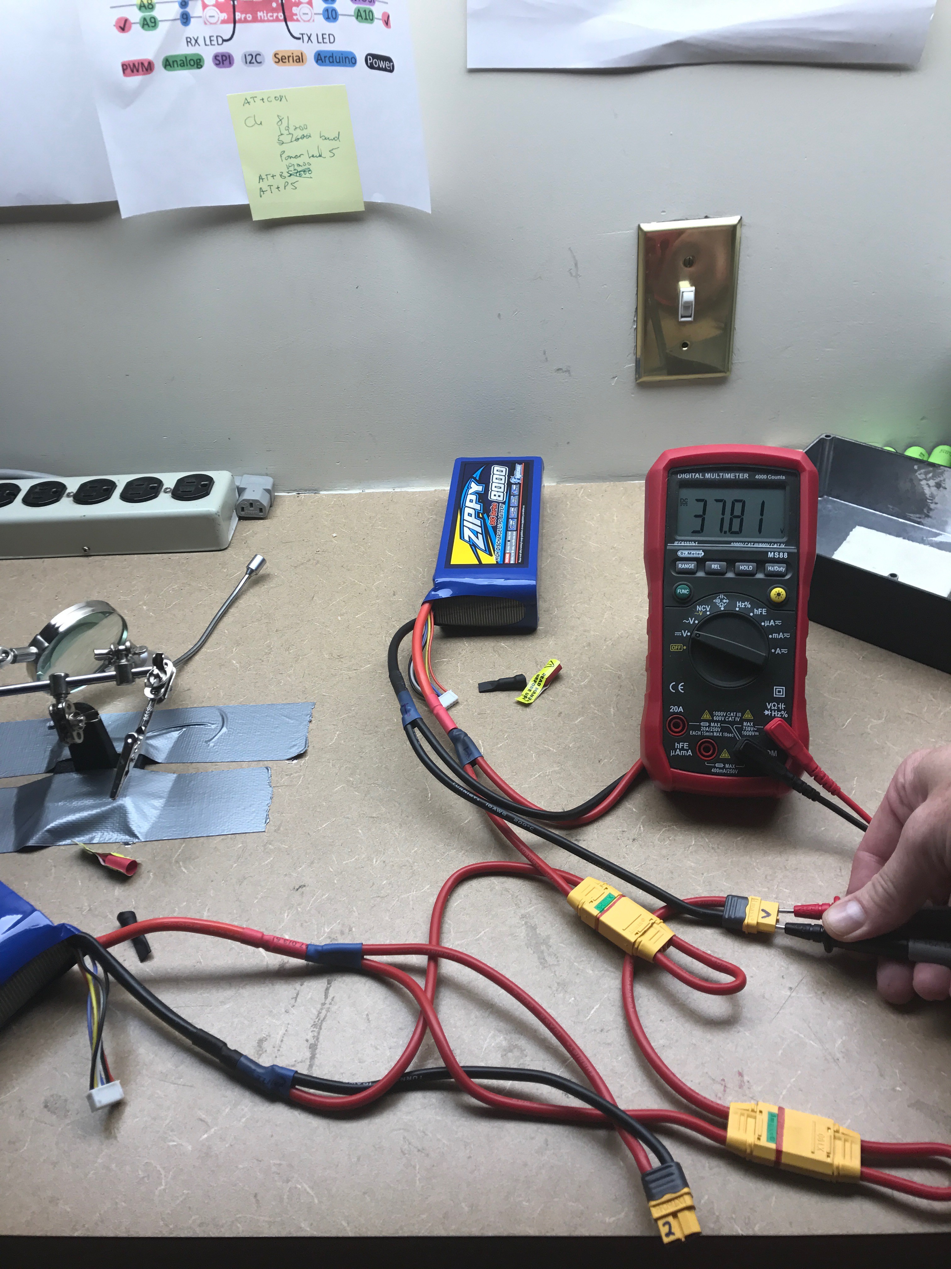 Both 10s batteries ( storage-charged at 50%) showing 37.81V. Note the 2 XT90 Jumpers in place. All this stuff has to fit in the small area in front of the batteries. I could have used shorted wires, but based on past experience I personally think it's easier to fit longer ones. Usually it's getting them to bend the way you need them to is the hardest part...not fitting all that wire..and longer wires are easier to bend. We'll see. I haven't mounted to the box yet and crammed it all in. I think it will fit.