dudeskidaddy
-
433 MHz Radio: A Quick and Dirty Work-Around
06/21/2016 at 21:26 • 0 commentsWanted to start riding. The hardware was done and we couldn't wait to get the NRF2401 based remote control working. So we spent a day building and getting a these super cheap 433 Mhz radios to communicate a simple integer value signal (throttle position 0-180) from our remote control Arduino Nano to our broad's Nano which would then control the motor speed via a separate PWM signal. Again, the idea is the skateboard-based arduino will slowly spool up/dn based on throttle position so we don't fall off, even if the radio link is lost (which happens a lot), the board's micro will just slowly spool down the motor rather that cut off all at once. (Note: We want to try this ourselves using cheap off the shelf ESC. (A $150 VESC would take care of all this spool up/dn, breaking and more...waiting for ours on backorder)
OK so, the 433 RF works! Took a while and figured out a few things.
- The Arduino Wiring and Servo libraries are NOT compatible because the both want access to the same interrupt timer. So you have to use this ServoTimer2 library which was written to get around this issue. Works like a charm. As usual, put this in your Arduino/Libraries folder and follow the example. NOTE...the API is different from the built in Arduino Servo library. You don't send a 0-180 value to servo.write() as you would to the default Servo library. Instead you send a micro second value (the actual pulse width from 750-2250). So if you are porting code from library to the other, you will need to map the values.
- Antenna Matters. We added the recommended 17cm wire to the transmitter. No luck..it used stranded wire. We added 17cm single core wire...still no luck. We twisted and coiled the wire a bit....That worked! This is needed to give us about 6-8 feet of range. Did we mention these radios kind of suck?
Here is a working bench remote control setup.
Here is our first grand day out...That's rattling sound is the aluminum battery box cover..got to put a gasket on that thing. Now that we know how this behaves, we'll be increasing the accretion and top speed.
-
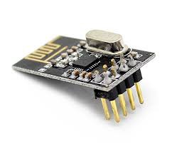
NRF2401 & our tran/rec code.
06/15/2016 at 21:41 • 0 commentsRadio Choice: NRF2401
We've been playing with a variety of transmitter-receiver hardware and settled on the Nrf24 for a few reasons. One, there is a very well documented and simple Arduino library for this: Arduino NRF2401 Library Second, we want the throttle control logic to reside on the skateboard micro, not in the remote. So rather than have the throttle send a single PWM signal straight to the ESC (using an stx882 for example), it will be sending the state of the throttle, and buttons as byte stream (currently 3 bytes). The idea is that in the event of a remote failure, the system has the opportunity to respond the way I want it to.. i.e. slow down. We can also add as many controls as I want to the remote..lights for example, because it's not limited to a single PWM signal.
(Update 8/6/2016 Turns out most ESCs handle a "loss of signal" by shutting down...which means free-wheeling. In the case of the VESC you can even program in a breaking force.)
![]()
Braking
After playing around with our $30 ESC we realized it has no brakes...waiting for out VESC. In the meantime were going to use it, moving on and getting this thing working and going for a ride with no brakes. Can't wait!
(update 6/20. Yes, riding with no brakes is fine for some situations...but after finally getting a VESC with brakes...there is just no going back. If you are thinking of building an electric longboard, you absolutely need to use a VESC with brakes. A hobby ESC is great for learning the electronics part, getting a board up an running really quickly and cheaply, but after that...you'll want one. A VESC is less than $90 now...not much more than a hobby ESC)
Features implemented in the code:
Inputs: Throttle Potentiometer and 2 buttons.
Setup Mode: Enables setting min/max throttle on the ESC
Acceleration Control: Be able to slow down throttle response to something reasonable for a skateboard. For example spool up/dn
Emergency Brake: Paranoid...in case throttle potentiometers goes nuts or you can't turn off power on remote.
Cruise: Maintains speed, only full throw of the throttle increases or decreases speed slowly.
Arduino Code:
We've been riding for a few weeks now, this setup seems to be pretty good. Use at your own risk.
Transmitter using Nrf2401 and Arduino
/* NRF2401 - Arduino Nano 1 - GND to GND 2 - VCC to 3.3V 3 - CE to D7 4 - CSN to D8 5 - SCK to D13 6 - MOSI to D11 7 - MISO to D12 8 - floating */ #include <SPI.h> #include "RF24.h" RF24 myRadio (7, 8); byte address[8] = {"myaddress"}; // Pick Your own unique address here byte data[3] = {0,0,0}; // 1st 2 bytes are pot, second byte is the 3 buttons (3 bits) int pot_pin = A0; // Arduino Nano int pot_val=0; int button1_pin = 2; int button1_val = 0; int button2_pin = 3; int button2_val = 0; int button3_pin = 4; int button3_val = 0; void setup() { Serial.begin(115200); delay(500); Serial.println(F("Starting...")); pinMode(pot_pin,INPUT); myRadio.begin(); myRadio.setChannel(111); myRadio.setPALevel(RF24_PA_MAX); myRadio.openWritingPipe(address); myRadio.stopListening(); delay(1000); } void loop() { unsigned pot = analogRead(pot_pin); // potentiometer data[0] = (byte) (pot & 0xFF); data[1] = (byte) ((pot >> 8) & 0xFF); bool b1 = digitalRead(button1_pin); // button1 bool b2 = digitalRead(button2_pin); // button2 bool b3 = digitalRead(button3_pin); // button3 b1=0; b2=0; b3=0; // Compress these 4 pieces of information into 3 bytes. 16bit in (pot) takes 2 bytes // 3 bits (3 buttons takes the 3rd byte. Minimize the transmission payload. data[2] = (byte) 0; //clear the byte..we're only going to use the 1st 3 bits. data[2]|= (byte) (b1<<7); // shift bit to MSB position data[2]|= (byte) (b2<<6); // shift bit to MSB -1 pos data[2]|= (byte) (b3<<5); // shift bit to MST -2 pos // if all 3 buttons are hi, data[2] = 11100000 or 224 viewed as an int Serial.println("About to write"); myRadio.write( &data, sizeof(data) ); // Transmit the data Serial.print(F("Sent ")); Serial.println(pot); delay(25); // approxx 30-40Hz frame rate...plenty } Receiver using Nrf2401 and Arduino /* NRF2401 - Arduino Nano 1 - GND to GND 2 - VCC to 3.3V 3 - CE to D7 4 - CSN to D8 5 - SCK to D13 6 - MOSI to D11 7 - MISO to D12 8 - floating */ #include <SPI.h> #include <ServoTimer2.h> // #include "RF24.h" // int pwm_pin=3; //digital pin3 connects to ESC RF24 myRadio (7, 8); byte address[8] = {"myaddress"}; // Pick Your own unique address here #define payloadSize 3 // bytes byte data[payloadSize]; bool cruise = false; bool ebrake = false; bool setupmode = false; bool setupPermanetOff = false; int centerRest = 504; // 0-1023 (where does the pot rest) int escMinPWM = 750; // ms pulse width int escMaxPWM = 2250; // ms pulse width of servoTimer2 int requestedThrottle = 0; // from 504 1023 0=rest 1023=max power int maxThrottleRange = 1000; // throttle will map 0 to this number, then to the esc Range. int maxEscThrottleGovernor = 750; // 0 to maxThrotteRange int escThrottle = 0; // actual throttle send to ESC 0-180 int minThrottlePot = 5; // pot isn't that great should be 0 int maxThrottlePot = 1020; // ditto (should be 1023 int counter = 0; int cruiseAccellThreshold = 950; // pot = 0 to 1023, represents very high throttle up ->slow accel int cruiseDecelerateThreshold = 50; // very low throttle dn command in cruise ->slow decel int breakMin = 400; // throttle position break values int breakMed = 250; int breakMax = 100; int movement = 0; // change in throttle from one iteration to the next int incr[5] = {5,7,9,11,13}; // throttle movement increments. unsigned last_good_signal; ServoTimer2 myservo; void setup() { Serial.begin(115200); delay(1000); Serial.println(F("eStakeboard Receiver Bootup")); myservo.attach(pwm_pin); myRadio.begin(); myRadio.setChannel(111); myRadio.setPALevel(RF24_PA_MAX); // Not sure if this is needed yet, MIN maybe ok. myRadio.openReadingPipe(1, address); myRadio.startListening(); last_good_signal = millis() ; } void loop() { if ( myRadio.available()) { last_good_signal = millis(); while (myRadio.available()) { myRadio.read( &data, sizeof(data)); counter = 0; } Serial.print("GOOD TRANS "); Serial.print(last_good_signal); Serial.print(" "); // decode the 3 bytes into an Int and 3 bits // 1st two bytes contain an Int. Shift them appropriately unsigned pot = (data[1] << 8) + (data[0] << 0); // 3 bits. Mask and shift right to get 0/1 in the LSB position // 0x80 = 10000000 (128 as an Int) 0x40 = 01000000 0x20 = 00100000 bool button1 = ((data[2] & 0x80) >> 7); // 1st bit of this byte bool button2 = ((data[2] & 0x40) >> 6); // 2nd bool button3 = ((data[2] & 0x20) >> 5); // 3rd adjustSpeed (pot,button1,button2,button3); Serial.print(pot); Serial.print(" "); Serial.print(button1); Serial.print(" "); Serial.print(button2); Serial.print(" "); Serial.print(button3); Serial.print(" "); Serial.println(""); } else { unsigned now = millis(); // expecting a signal every 25ms or so if ( abs(now - last_good_signal) > 35 ) { last_good_signal = now -36; // int will overflow eventually and give errorneous results adjustSpeed (centerRest,0,1,0); // sending neutral throttle signal Serial.print("Signal loss "); Serial.print(now); Serial.print(" "); delay(25); // same delay as transmitter. Slow down to 0 should be same. } } } void adjustSpeed(int pot,bool setupModeButton, bool ebrake, bool cruise) { if (millis() > 10000) { setupPermanetOff = true; } // setup mode only allowed in the fist 10 seconds with button1 hi // in setup mode throttle position = esc throttle position...no delay if (setupModeButton == true && !setupPermanetOff) { setupmode = true; } else { setupmode = false; } if (setupmode) { // no governor requestedThrottle = map(pot,centerRest+5,maxThrottlePot,0,maxThrottleRange); } else { requestedThrottle = map(pot,centerRest+5,maxThrottlePot,0,maxEscThrottleGovernor); } if (ebrake) { // as if there is no throttle input requestedThrottle = 0; } // normal mode: accelerate only when requested throttle is higher than esc // cruise mode: accelerate only when requested throttle is fully pegged hi/lo if ((!cruise && escThrottle < requestedThrottle) || (cruise && requestedThrottle > cruiseAccellThreshold)) { movement = incr[0]; // lowest of the increments // When ESC is at a low setting...under a load we need more throttle response // lets get it moving along quicker then. if (escThrottle < 25) { movement = incr[4]; // start a bit quicker..use max increment } else if (escThrottle < 50) { movement = incr[3]; // } } else if ((!cruise && escThrottle > requestedThrottle) || (cruise && requestedThrottle < cruiseDecelerateThreshold)) { movement = -incr[0]; // brakes: if the pot is < centerRest, start coming off the gas quickly if (pot < breakMax) { movement -=incr[4]; } else if (pot < breakMed) { movement -=incr[2]; } else if (pot < breakMin) { movement -=incr[1]; } } else { movement = 0; // no change in speed requested } escThrottle += movement; // apply change if (setupmode) { // constrain throttle to min/max escThrottle = constrain(escThrottle,0,maxThrottleRange); } else { escThrottle = constrain(escThrottle,0,maxEscThrottleGovernor); } // finally map to the esc PWM int pwmVal = map(escThrottle,0,maxThrottleRange,escMinPWM,escMaxPWM); myservo.write(pwmVal); Serial.print("Setup: "); Serial.print(setupmode); Serial.print(" ESC Throttle: "); Serial.print(escThrottle); Serial.print(" PWM : "); Serial.println(pwmVal); } -
Electronics and Remote Control
06/13/2016 at 17:36 • 0 commentsWe wanted to build our own transmitter receiver. Lots of options here. Right now we're playing with Arduino/ATTNIY85 communicating over Serial RF using 2 HC-12s. Need to make sure we get a consistent signal, can transmit data fast enough...figure 20 updates/second is more than enough. This is all under development and haven't made any attempt to drive the motor via Serial communication yet.
In the meantime...we really wanted to play with that motor...and also some basic control logic. The biggest concern will be how to slowly spool up and spool down the motor when the rider moves the throttle quickly. Our ESC (engine speed controller) has only a few options here...so we're forced to do all this in the controller.
We're using a thumb-stick from Spark-Fun and generating a PWM signal from our Arduino Nano that is directly wired to the ESC. We wrote some code to enable a "setup mode" when starting the remote control while holding down the thumb-stick button. This is useful for calibrating the min/max throttle. We also added some logic to slowly spool the motor up/dn. We use a 25ms delay in the control loop, and add/subtract 1 from the PWM value for each iteration.
Speed Control: Right now I'm limiting the motor speed to 50% by simply limiting the PWM sign to half the max value we used when setting up the ESC. Haven't used this yet, so not sure how limiting speed affects torque. I'd like to get max torque for good acceleration, but limit the top speed for safety. Maybe need a better ESC for that, an engine speed sensor...not sure, yet.
I'm hearing a little wheel / belt alignment in this vid. Not really able to get that rear sprocket 100% aligned to the wheel and it has a very very slight wobble... Something to think about.
(update 6/4/2016 The spool up/spool down speed is impossible to measure upside down and un-loaded. Unloaded the motor can go from 0 to full speed practically instantly. Under load it might take a few seconds. The purpose of calibrating acceleration is to make it take around 6 seconds so you don't fall off)
-
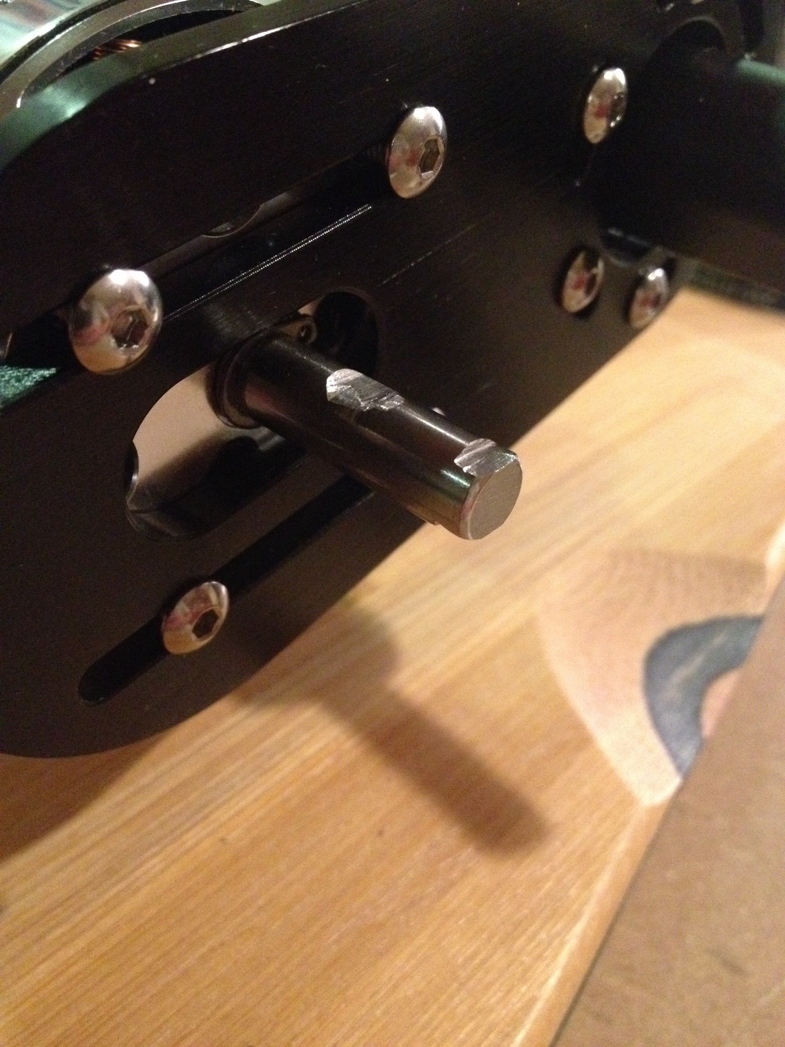
Squaring up the motor shaft
06/13/2016 at 17:06 • 0 commentsOur motor has a smooth shaft and there's no amount of force you could apply to a set screw to hold that thing in place under load. So we need to create some flat spots. There seem to be a few opinions out there on how to best do this....here is what we tried.
We ground down these flat spots for the set screws.
![]()
We figure out where to file the motor shaft, we first assembled the motor to the mount, placed the sprocket in position and tightened the set screws which made small marks in the shaft. We then removed the set screws, mount and sprocket and marked the small dents we just made with a permanent marker. Put the motor in a zip lock bag to prevent iron shavings from getting sucked into the motor with the shaft poking out. We used a dremmel with the wide sanding bit. The dremmel was fast, but it wasn't very controllable. The flat spots weren't very flat and consistent. I found using the edge of a file worked best...fairly flat and somewhat consistent. Won't really know how well this works until we can test it under load.
(update 7/4. It worked well and the set screws hold the sprocket under load, bud we've had to re-tighten the screws 1-2 times even though we're using lock-tight.)
I can't believe they make motors with smooth shafts. From a torque transfer point of view I can't imagine a worse cross-section. Probably settled on this because it's too hard to get everyone to agree on a standard. At least everyone seems to have agreed on a standard diameter.
(update 8/10/16 Yes, they do make a better motor with a profiled-shaft. The Enertion 190KV R-spec motor. We're using on our next longboard project. )
-
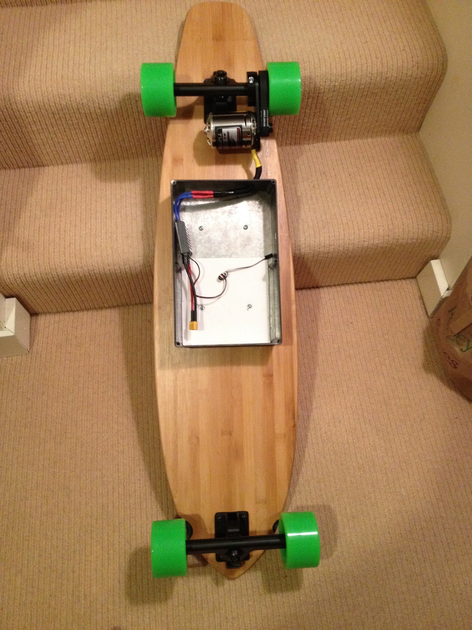
Assembly
06/13/2016 at 16:49 • 0 commentsOk so we're done doing the physical assembly...had a few issues along the way.
The battery box clearance (rear-mounted) might be problem for speed bumps. Current clearance is only about 2 inches. Hard to find an aluminum (for heat sink) case big enough to fit 2 batteries, esc, wiring and ports but also not be too tall. Might have to change this. I'd rather not use thick risers.
(update: 10/7/2016 yes, the battery box in the back is bad idea...it can strike the ground in suck a way as to throw the rider. We have since moved it to the front where if it does strike the ground/speed bump, the board continues on and just slides off. Also, no need for heat sink in the battery box, they don't ever get warm. We did keep the ESC in the back and in s small plastic box to prevent interference with the remote/radio)
![]()
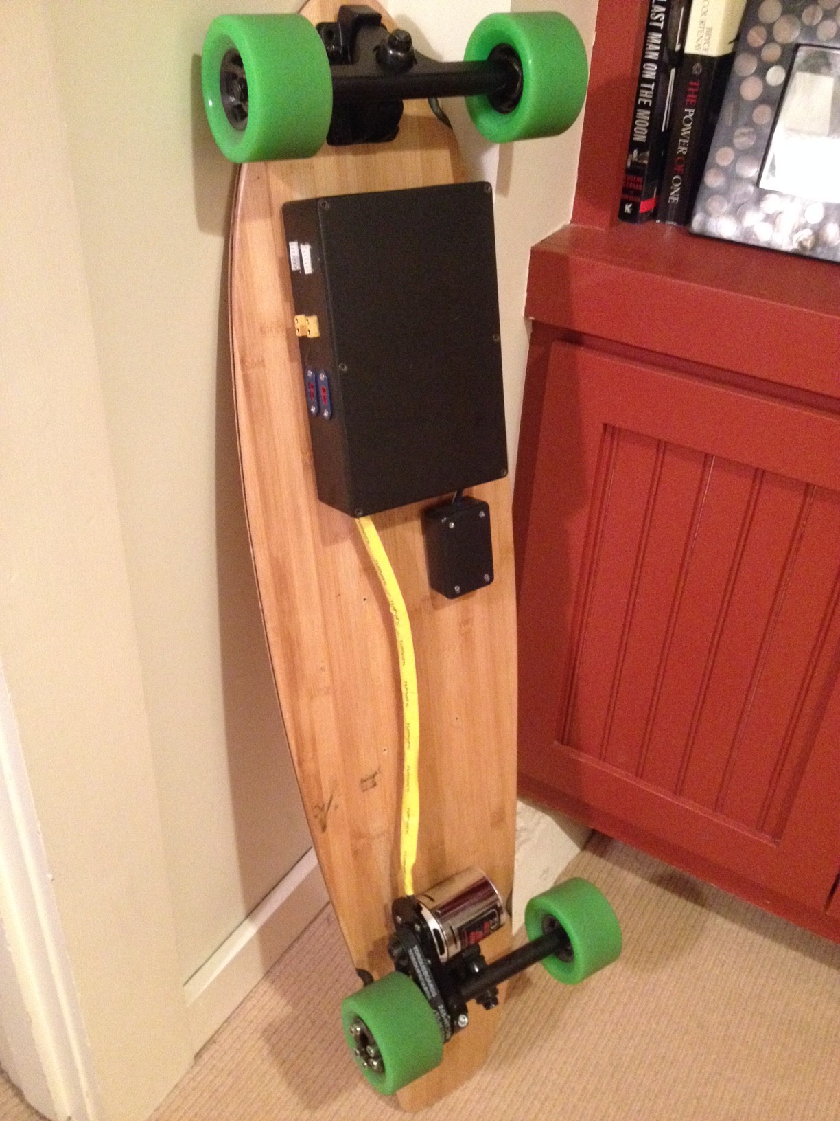
Battery box - deck rattle
Another trick was putting thick rubber 0-rings or bushings between the battery box and the board. We got a lot of noisy vibration for the box banging against the deck until we added these. Sorry, not shown in the pic. Here is the front mounted battery box before we moved the ESC to the back.
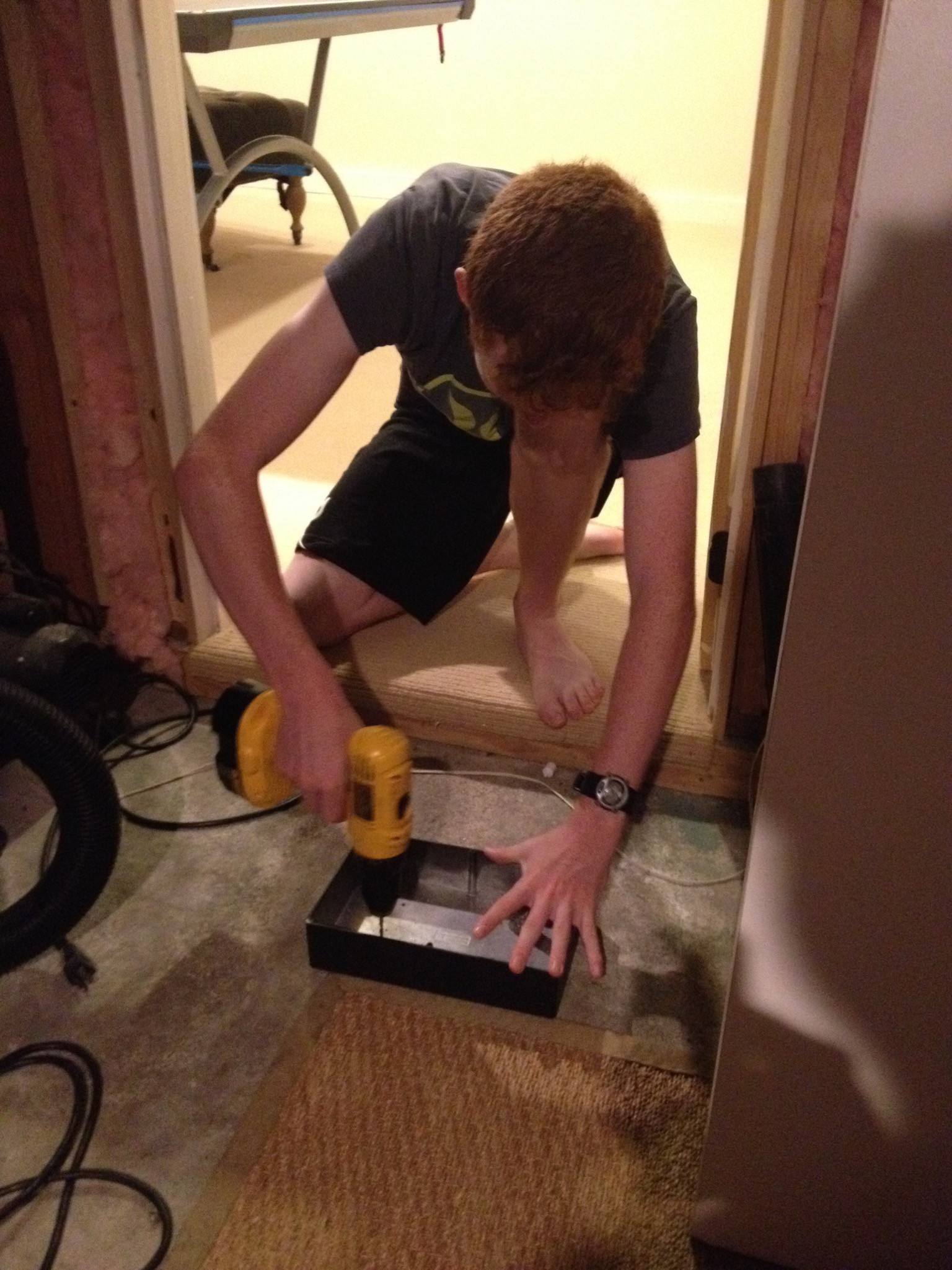
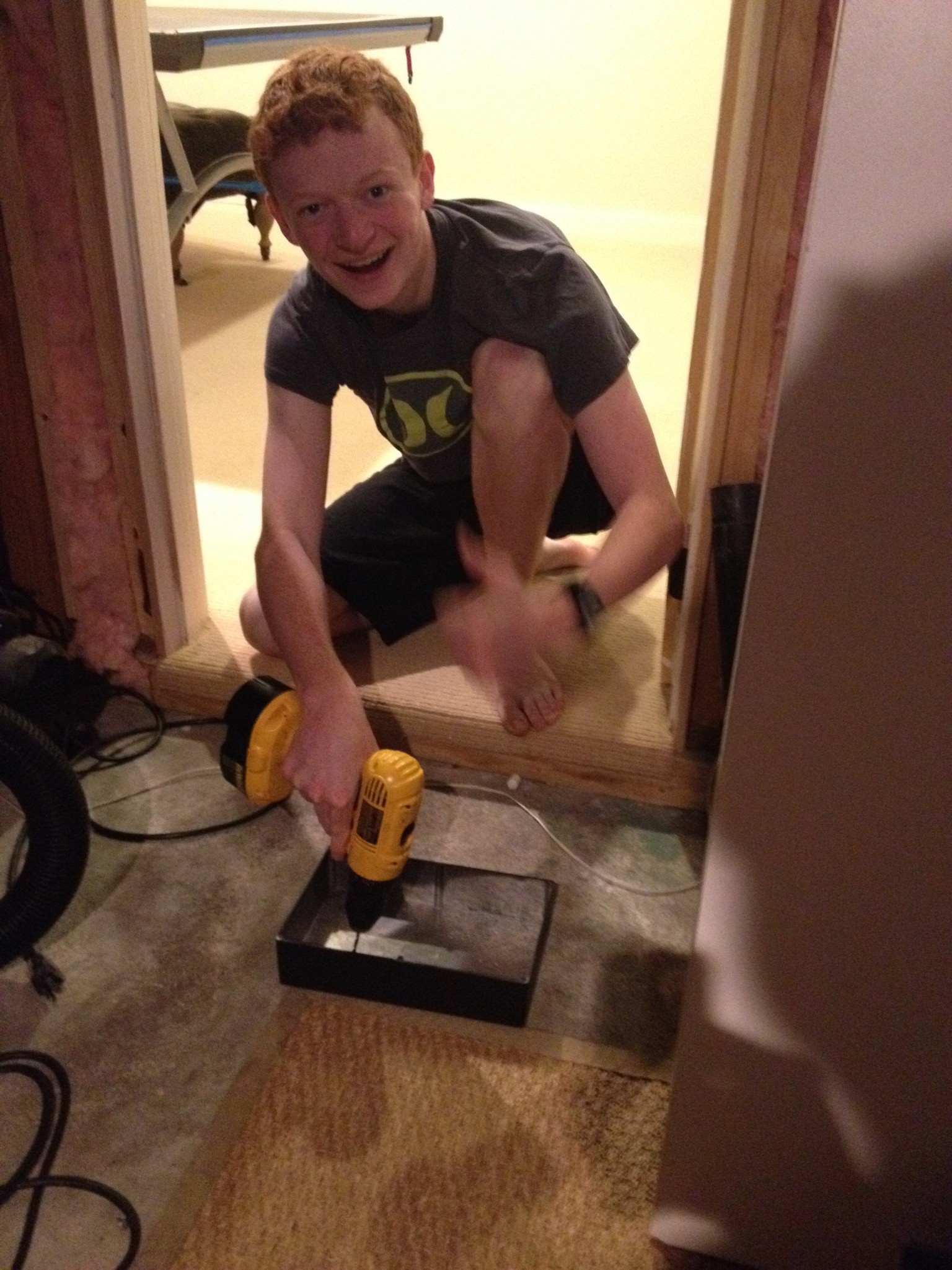
![]()
Jack getting to work on finding the right spot, drilling some holes. We used a few rubber washers between the board and battery case. The bottom of the board is not flat...a bit convex...so the washers made up for this...and also provided some cushion. We decided to use wood screws for the box rather than through bolts to keep the upper side of the deck clean.
![]()
![]()
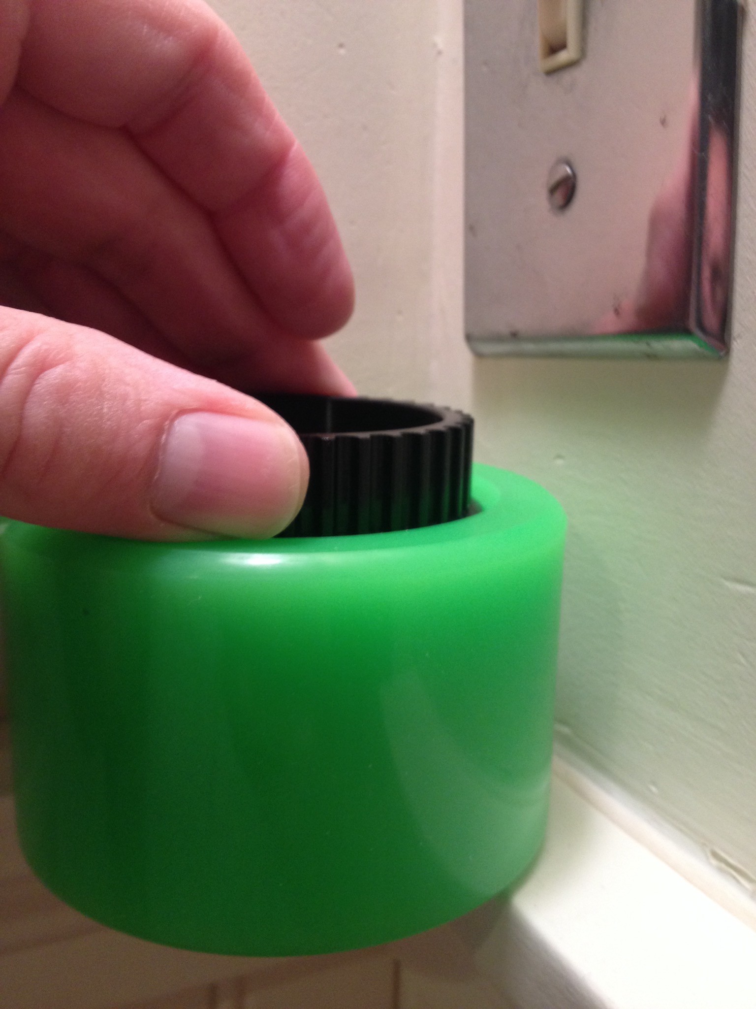
Next issue was the rear wheel sprocket (from DIY Electric Skateboard). As you can see, the sprocket doesn't fully clear the wheel by about 1-2 mm. So the belt doesn't ride perfectly in the sprocket. We might be a bit nick-picky here but this kind of thing might lead to earlier belt failure?. guys at DIY Electric were great...very responsive and we talked about what to do.
The sprocket is a little bit inside the wheel's recess.
![]()
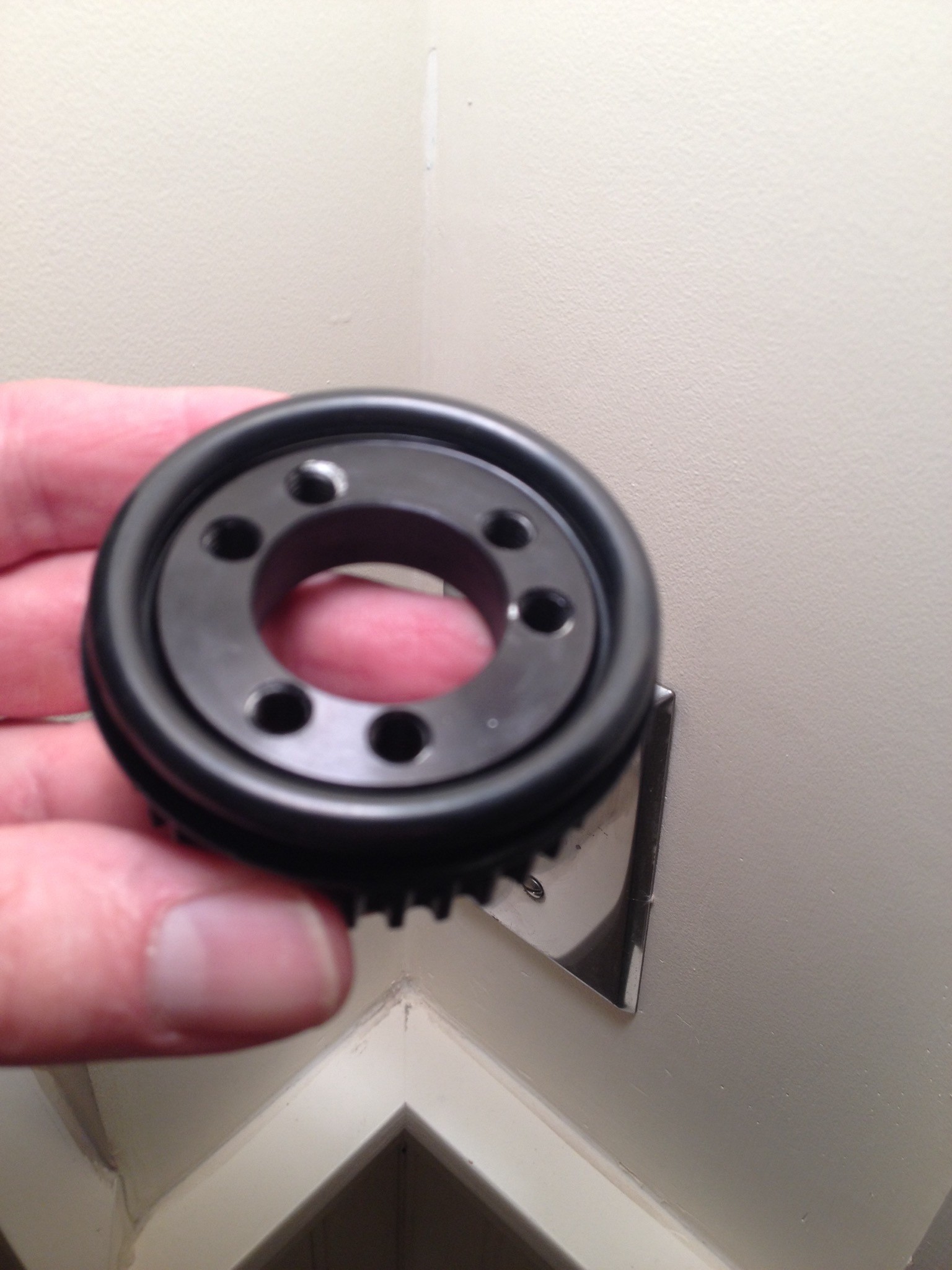
As a result, the belt is not able to fully mesh with the teeth.
![]()
There are 2 ways to get the sprocket in the right position.
Both work, but #2 is better.
#1: Shown below is the $0.50 solution at ACE hardware in the form of 2 Rubber 0-Rings that fit nicely on the sprocket as long as the bolts are not too tight.
#1: The final solution that worked even better was to use a 1mm aluminum disk as a spacer (identical to the ring used on the outside of the wheel that the bolts but this one is slightly thinner) that the guys from DIY Electric Skateboard sent. Because the spacer is a solid piece of aluminum, the sprocket has it little less wobble than it did using the rubber O-rings. You can also tighten the screws a bit more. Turns out you can hear even a tiny bit of wobble when you run the motor. So looking from the inside to outside of the wheel assembly we now have (Sprocket > Spacer > Wheel > Retaining Ring > 6 bolts. Also using blue lock tight.
![]()
![]()
Brook putting everything in place....
![]()
Now the sprocket has the full 12mm clearance.
![]()
The motor mount assembly was fairly straight forward. Had to move it around a few times to get the belt lined up and keep things from scraping. A few things that helped.
- Motor Mount. The mating between the trucks and the motor mount is the trickiest part. The Single Motor Mechanical Kit includes a bit of heat shrink tape that absolutely has to be in place or the mount will wobble. Somewhere down the line, someone will offer a good mount that stays in place. This setup is only ok ...you can get a tight fit and align the parts, but isn't perfect. Not sure how this is going to work out.
(update: 7/2/16. We've had a blast riding the board now for about 4 hours but as predicted, we had to replace that little piece of heat shrink several times as it wore down and almost fell out. No matter how tight you make it, the mount will wobble just enough to cause a bit of wear over time.)
-
Power Schematic
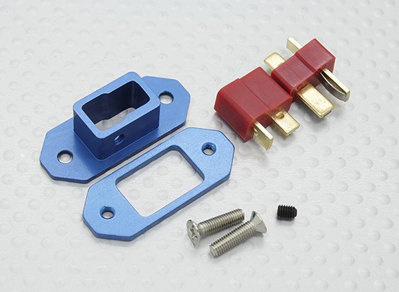
06/07/2016 at 21:11 • 0 commentsMy first concern with a 2-battery setup was how to safely enforce that only one battery be enabled at a time and absolutely no possibility of shorting power to ground. I didn't like any of the high-watt switches or relays out there. Well, there really aren't any 50A DC switches and the relays I found where expensive ($50) and resistive...tended to heat up. We found these ports and will create a jumper (below) to use as an ARM-ing switch. We didn't want to use XT60 ports as the arming jumper because we're using XT60 ports for the battery charger. Accidentally jumper-ing (shorting) the charge port would likely create a LIPO fire. This way, there is no way to mistakenly do arm the wrong port.
We only made one jumper so you can't enable both batteries at the same time. To run battery 1 or 2 put the jumper in jumper slot 1 or 2. To charge just remove the jumper and plug in the charger to either port.
![]()
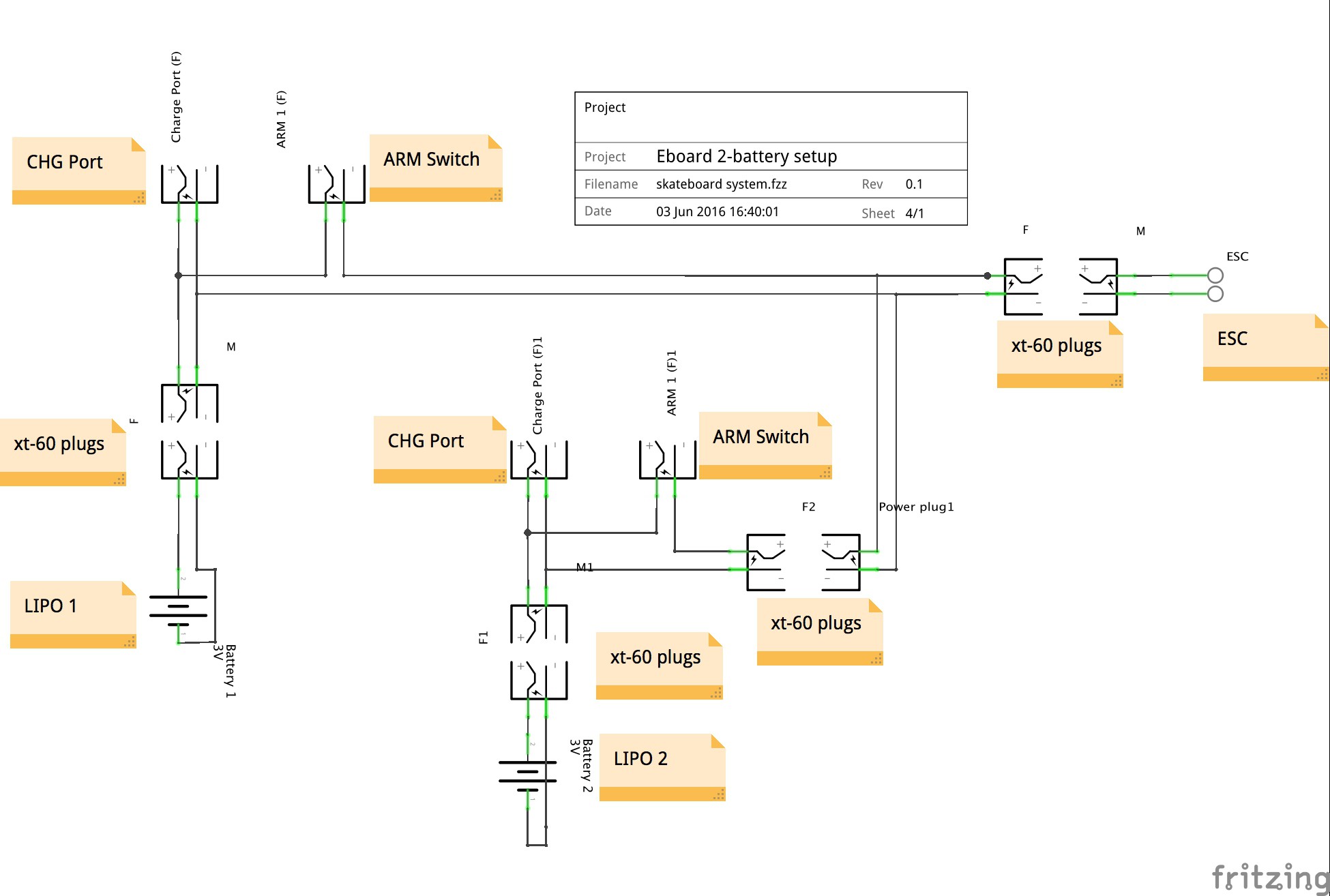
Here is wiring schematic Next time, I'll just hand-draw it.
![]()
Electric Longboard
Can we build a great board for under $400 in less than 3 weeks? (using a few pre-made kit parts)