-
It's alive!
01/20/2018 at 23:10 • 0 commentsThis took longer than expected... The macine finally placed it's first real board today! :) (A panel of 8 optically isolated USB-UART adapters). Many parts of the design has changed (some several times), an update is coming soon.
-
Video and updated documentation
08/20/2014 at 19:59 • 0 commentsI have uploaded my video for the Hackaday Prize to YouTube and uploaded my design outline and my CAD-file for the mechanical design. Look at the left side for links.
The design outline is the file to get if you want the most up to date and complete description if the project.
-
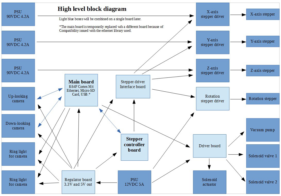
Updated System Design
08/19/2014 at 18:40 • 0 comments![]()
-
Overview of the software
08/19/2014 at 18:34 • 0 comments![]() Main MCU layered software diagram.
Main MCU layered software diagram.![]() Stepper controller MCU software diagram.
Stepper controller MCU software diagram. -
Update: Mechanical parts
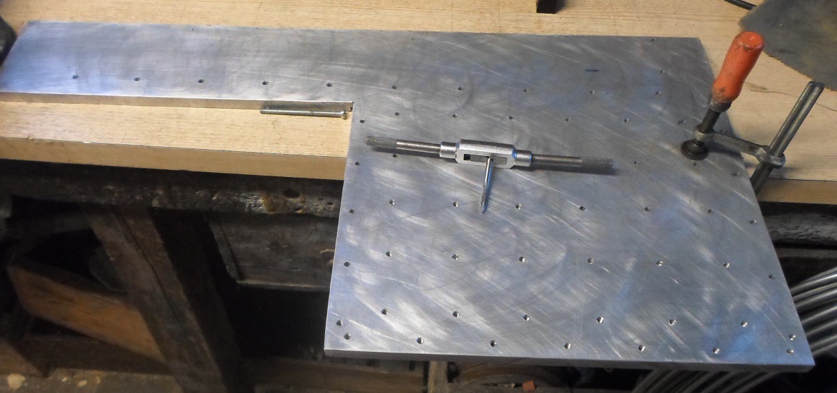
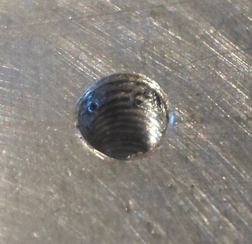
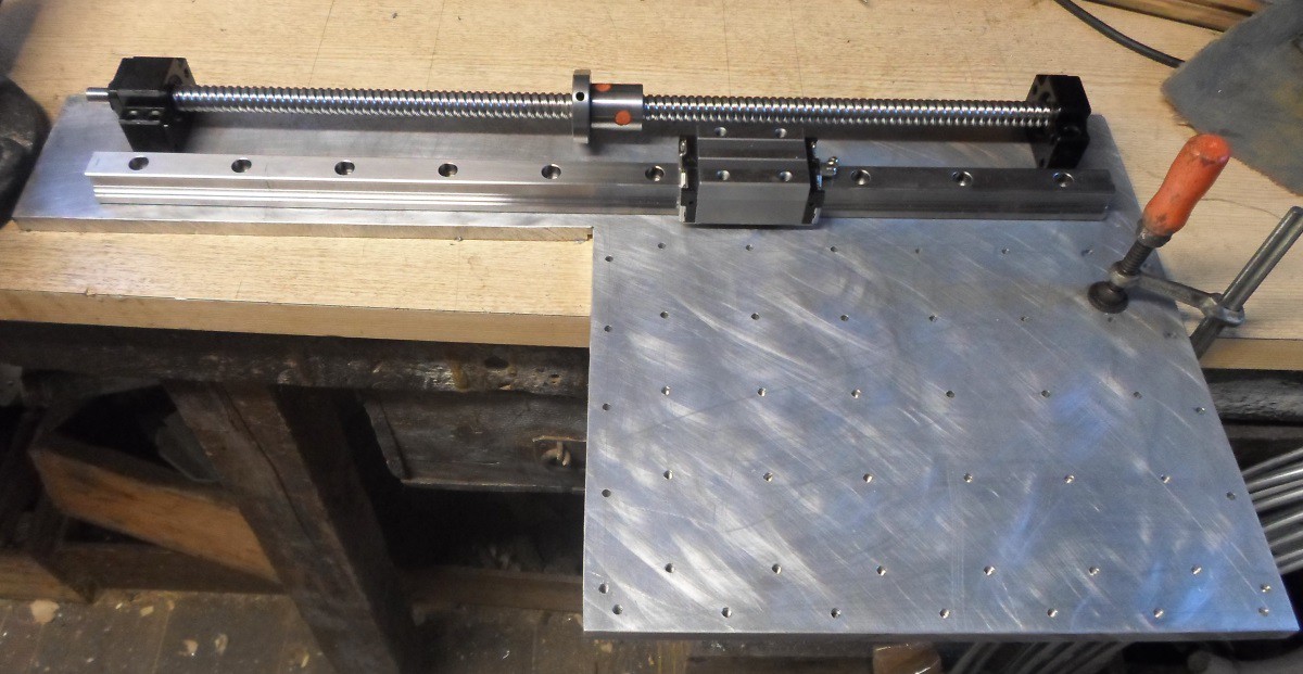
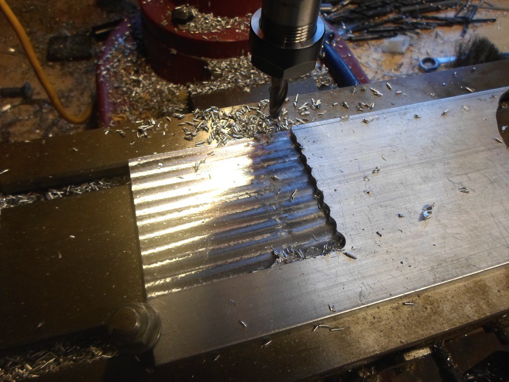
07/31/2014 at 16:19 • 0 commentsI'v been working on the base plate and some other mechanical parts of the machine. The base plate has a large number of M5 threaded holes to attach the feeders and fixtures for holding the board beeing populated. I'v finished drilling the holes, but I'v not finished tapping all yet. The Y-axis linear rail, ball screw bearings and motor mount also attaches to the base plate.
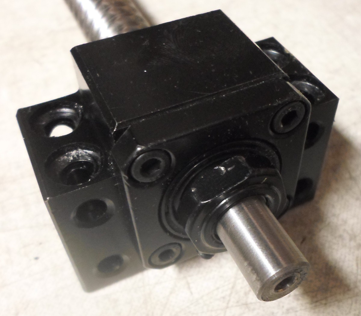
I was a bit worried about the fit of the ball screws into the bearings, but there was no problems. I left the bearings in a warm place and put the screws in the freezer. With 50 or 60C difference in temperature the bearings could be pushed on, no hammering required.
![]()
![]()
![]()
![]()
![]()
![]()
-
Update: Electronics
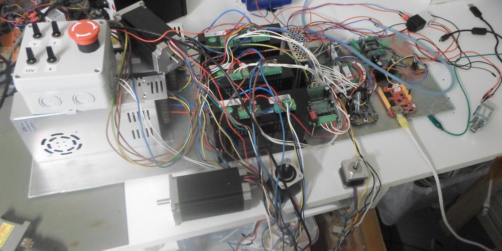
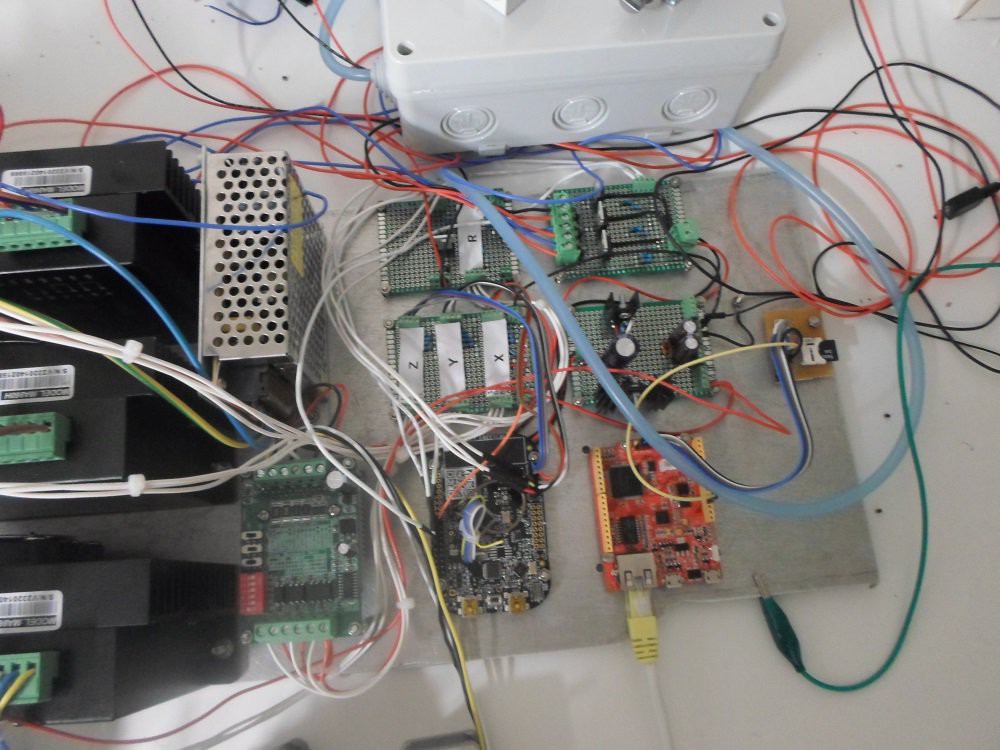
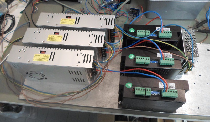
07/31/2014 at 15:38 • 0 commentsI finished hooking up all the electronics except the cameras and the limit switches about 3 weeks ago. Here's some pictures.
![]()
![]()
![]()
![]()
-
Progress update
06/24/2014 at 08:45 • 0 commentsStepper driver
I have finished the firmware for the stepper controller. This is a separate microcontroller which receives commands from the main microcontroller over UART. Each command consist of which axis to move, which direction and how many microsteps to move. The stepper controller calculates ramp up timing etc. Step generation is the only part of the firmware where timing is critical, so keeping it separate simplifies the rest of the firmware.Change of main MCU
I have switched to a LPC1768 based Arch-Pro board for the main microcontroller. Ethernet is now working reliably. Since this board doesn't have a socket for SD-cards I made a small board with a micro SD-card socket.Other..
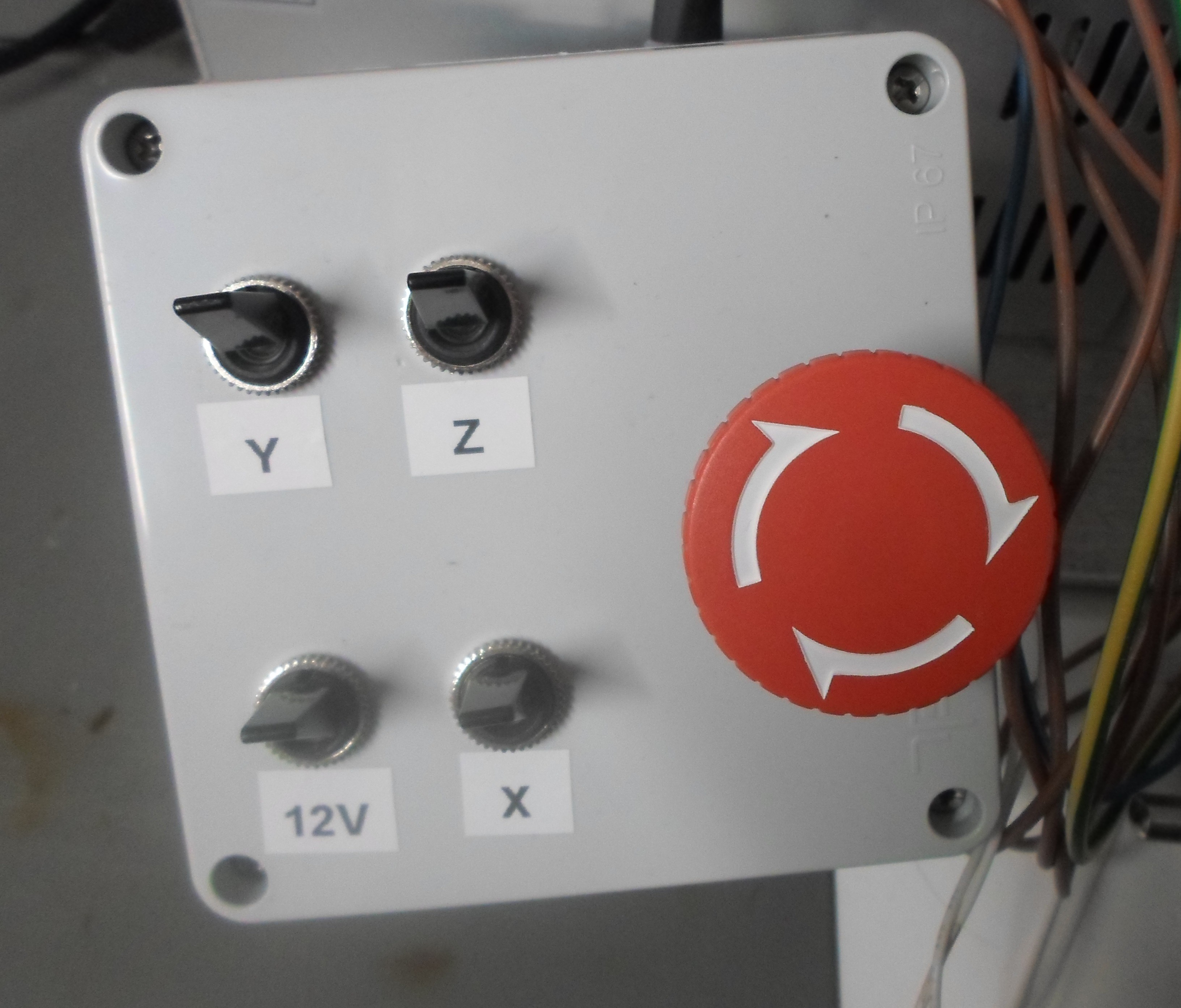
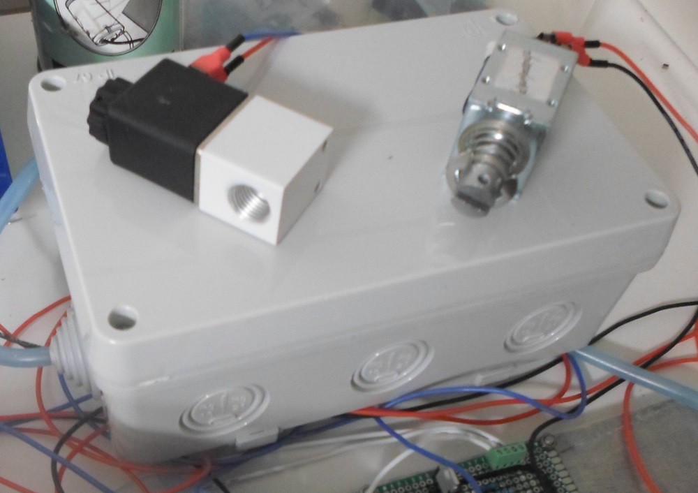
I have made a box with individual power switches for each power supply and an emergency stop switch. I'v (somewhat) sound proofed a box for the vacuum pump.I'm still waiting for the ball screws to arrive. I would like to have the ball screws before I start machining the parts so that I can verify that the dimensions I have based my plans on are correct. I'm also waiting for some ER20 collets for the mill. Once I have these I can do all the machining in a day or two.
-
Received more parts
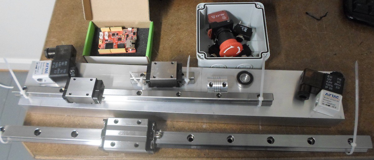
06/19/2014 at 17:50 • 0 commentsI have received most of the parts I need for the project, except the ball screws and bearings.
![]()
-
Hardware progress
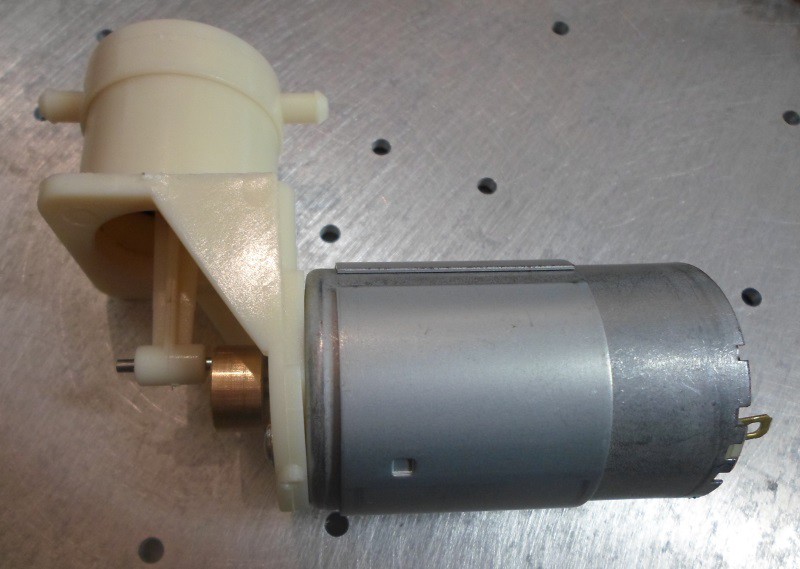
06/15/2014 at 19:56 • 0 commentsI have received the vacuum pump. I have tested it and there was no problem picking up components, so it looks like it's large enough. It's a bit noisy, but not too bad. I will mount it in a box to dampen the sound a bit. The power for the pump will be controlled by PWM to keep it running as slowly as possible to make it last longer and to reduce noise.
![]()
I cut a aluminium plate to size and drilled holes to mount all the power supplies, stepper drivers and all the boards. I'm mounting everything like this to have it easily accessible for probing and modifications. In the finished version all of this will most likely go into the base of the machine.
![]()
I'v cut out the base of the machine from a 12mm aluminium plate. (No picture yet.) Next I will drill and tap all the holes needed to mount feeders, the Y-axis linear rain, stepper mount, bearing blocks and the PCB holding fixtures. I will cast an epoxy-granite composite base under the plate, but I have not decided if I'm going to do it before assembling the machine or as an improvement later.
-
Software progress
06/15/2014 at 08:15 • 0 commentsI'v been working on the software and have made some progress. I have decided to run the software on two micrcontrollers instead of one, that way I can separate the timing critical step generation for the stepper drivers from everything else. The MCU controlling the steppers is a Cortex M0+, for prototyping I'm using a FRDM-KL25Z board. The stepper controller is about 50% finished. My Salea logic analyzer turned out to be very useful for this, I use it to check the timing of the signals from the MCU to the stepper drivers.
Support for Ethernet on the K64F by the mbed libraries has turned out to be unfinished/buggy. Because of this I'm going with an LPC1768 MCU on a Seed Studio Arch-Pro board. This MCU has some disadvantages, such as lower frequency, no FPU and less RAM, but I think the advantage of stable libraries outweighs this. For this project only the smaller RAM matters as it can't hold a complete picture from the camera in memory at once. My algorithm for finding the location of components in the images doesn't require the whole image to be in memory so this is not critical but more memory would be nice. I may switch back to the K64F if and when mbed support improves.
Pick and place machine
A pick and place machine optimized for small runs of different boards. Up/down looking cameras. Large number of feeders. Fast. Web interface
 ZeptoBit
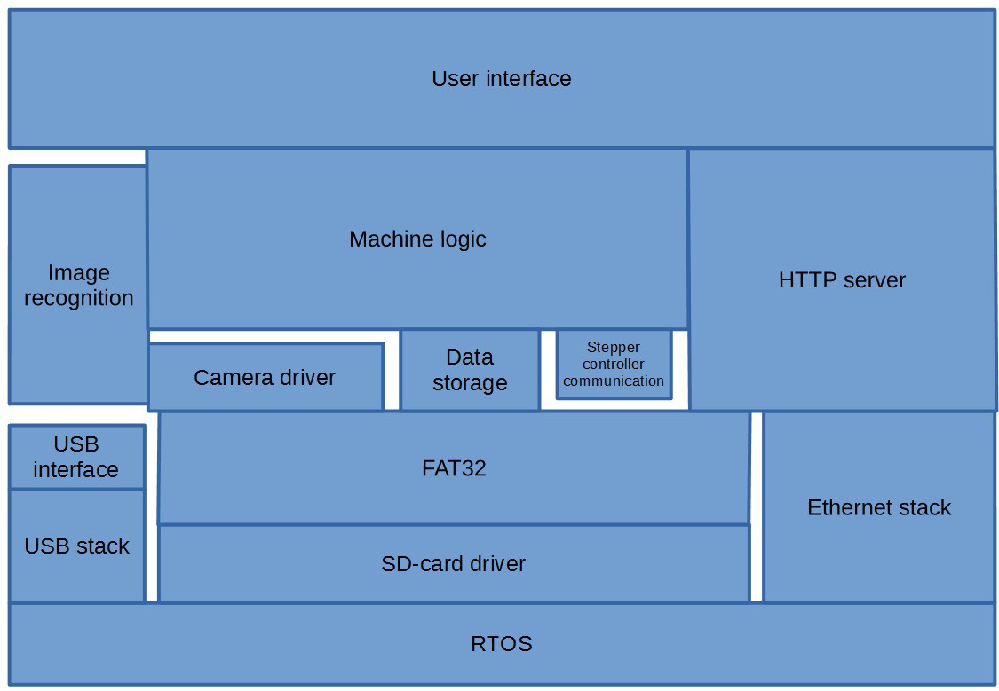 Main MCU layered software diagram.
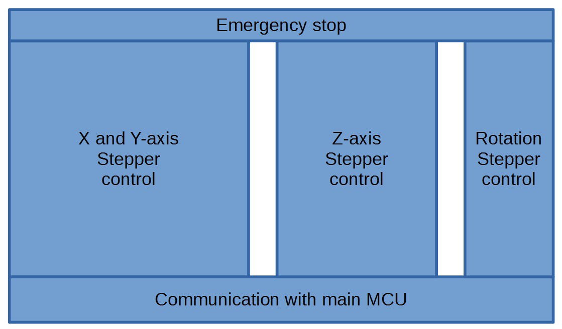 Stepper controller MCU software diagram.