 Saimon
-
1Get the PCB
To make one I2C Encoder V2, the first thing that you need is the PCB. On GitHub or in the Files section, there are the gerber files.
The PCB is 4 layer, this makes a bit complicated to do at home, for this reason the best option is to send the gerber file to some PCB manufacturing.Once you have the PCB, you can start to solder the components.
![]()
-
2Start to solder the MCU
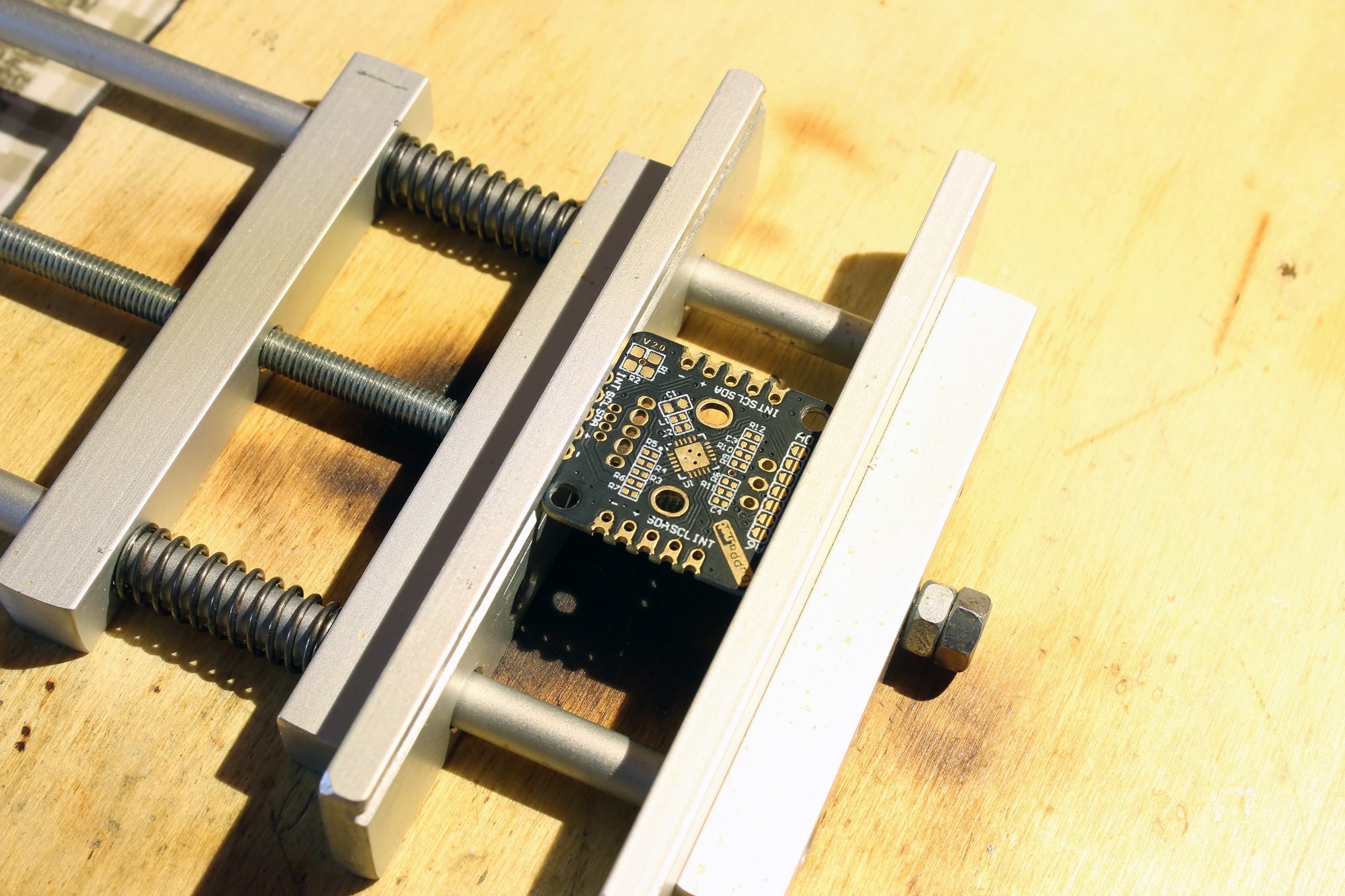
The first component that you need to solder is the MCU. The MCU is the PIC16F18345 and the package is a 20 pin QFN package.
There are many tutorial about soldering the QFN chip, my technique is the following:- Tinning all the pad
- Add flux
- Place the chip
- with the hot air melt the tin
- Necessary to add extra tin if some pads looks not soldered, or remove the extra tin
- Clean

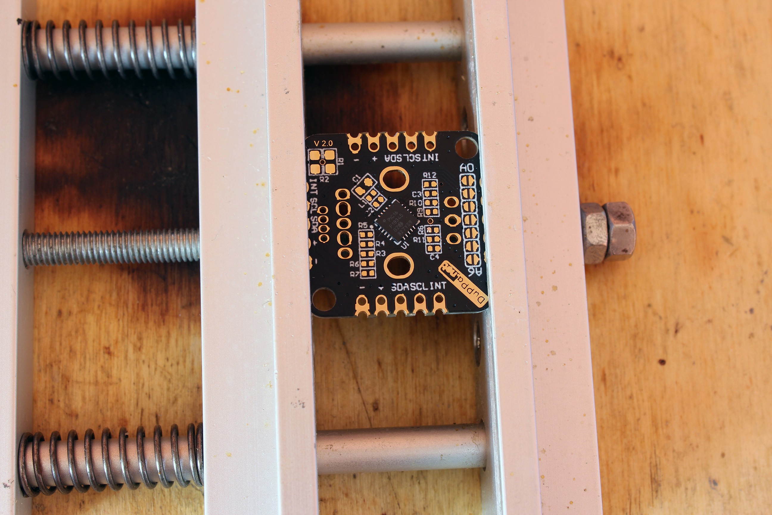
All the pads of the MCU must be soldered. ![]()
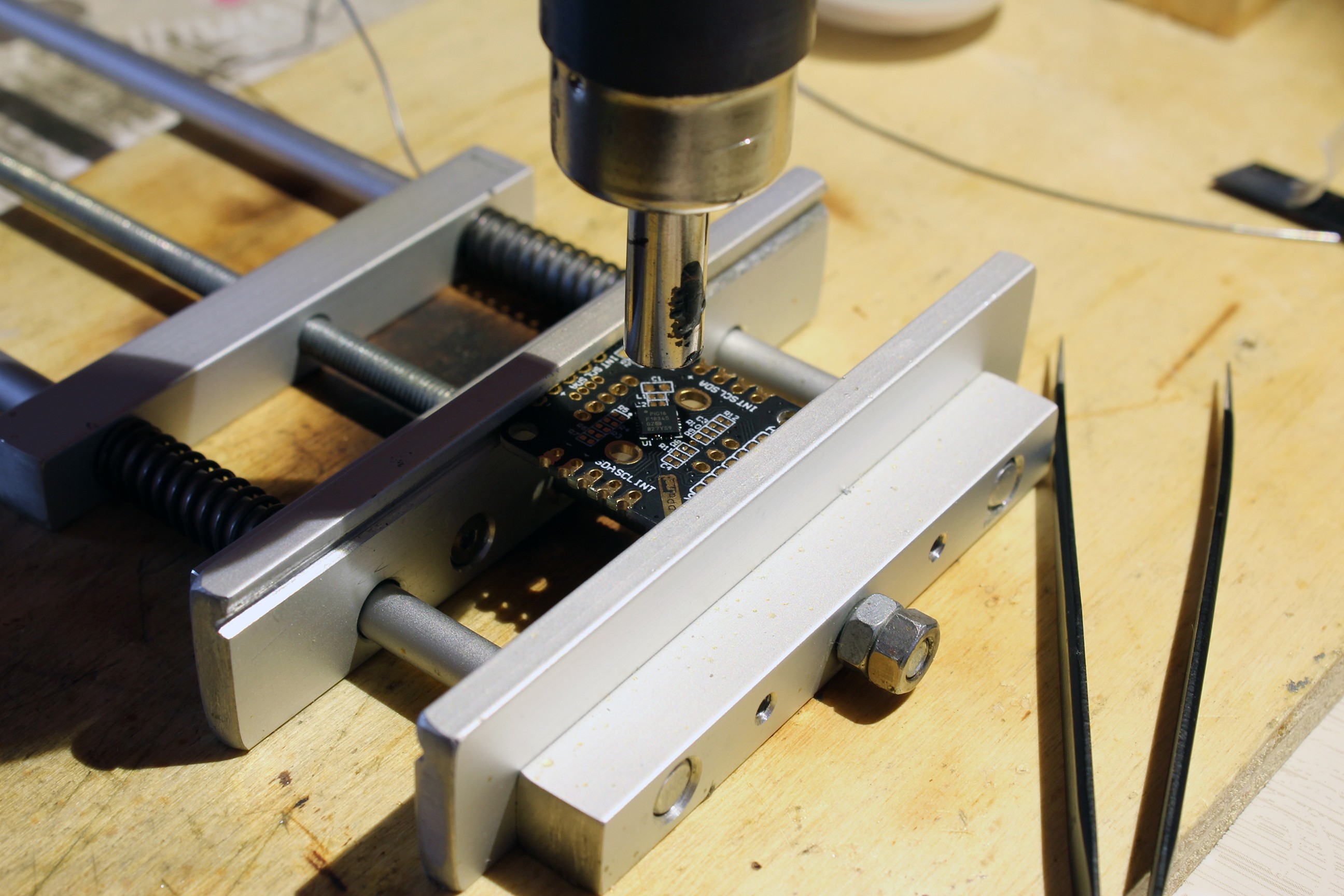
With the hot air to finish to solder the chip ![]()
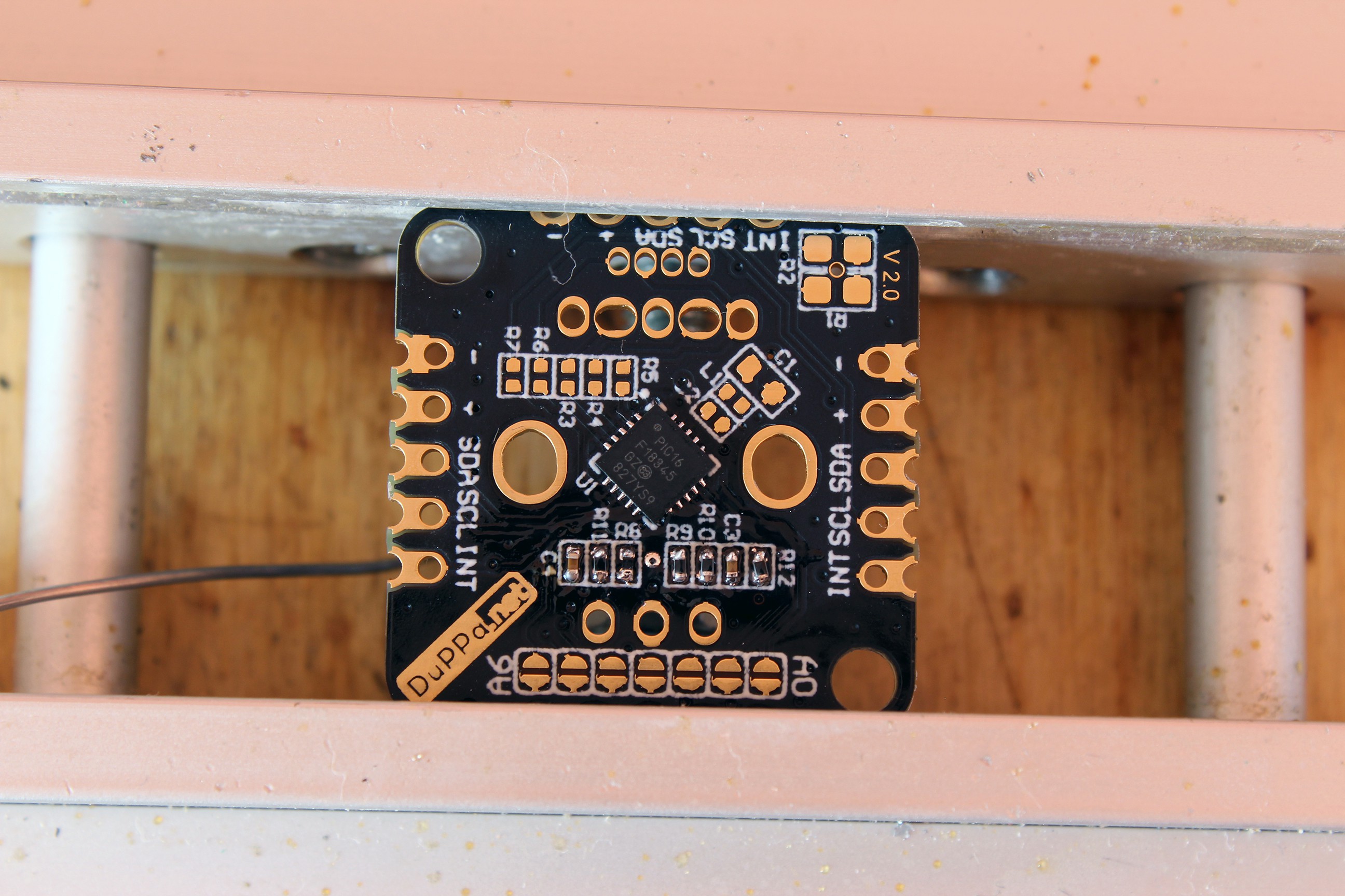
MCU successfully soldered and cleaned -
3Start to solder the passive componets
Once the MCU is soldered, it means that the difficult part is done.
Now you can start to solder the capacitors and the resistors. My method is the following:
- Apply the solder only to one pad
- Solder the component on that pad
- Solder the other pad
Generally i start with the 10k resistor and the 47nF capacitor.
That components are R8, R9, R10, R11, R12, C3 and C4.![]()
Components are soldered on one side ![]()
Components are soldered on the both sides -
4Continue to solder the rest of the componets
In the same way you can continue to solder the rest of the components.
Generally i continue with the 47r resistor, they are: R3, R4, R5, R6, R7.
![]()
47r resistors are soldered Now the last 3 components to be soldered are C1, C2 and L1.
![]()
All the components are soldered -
5Optionally components
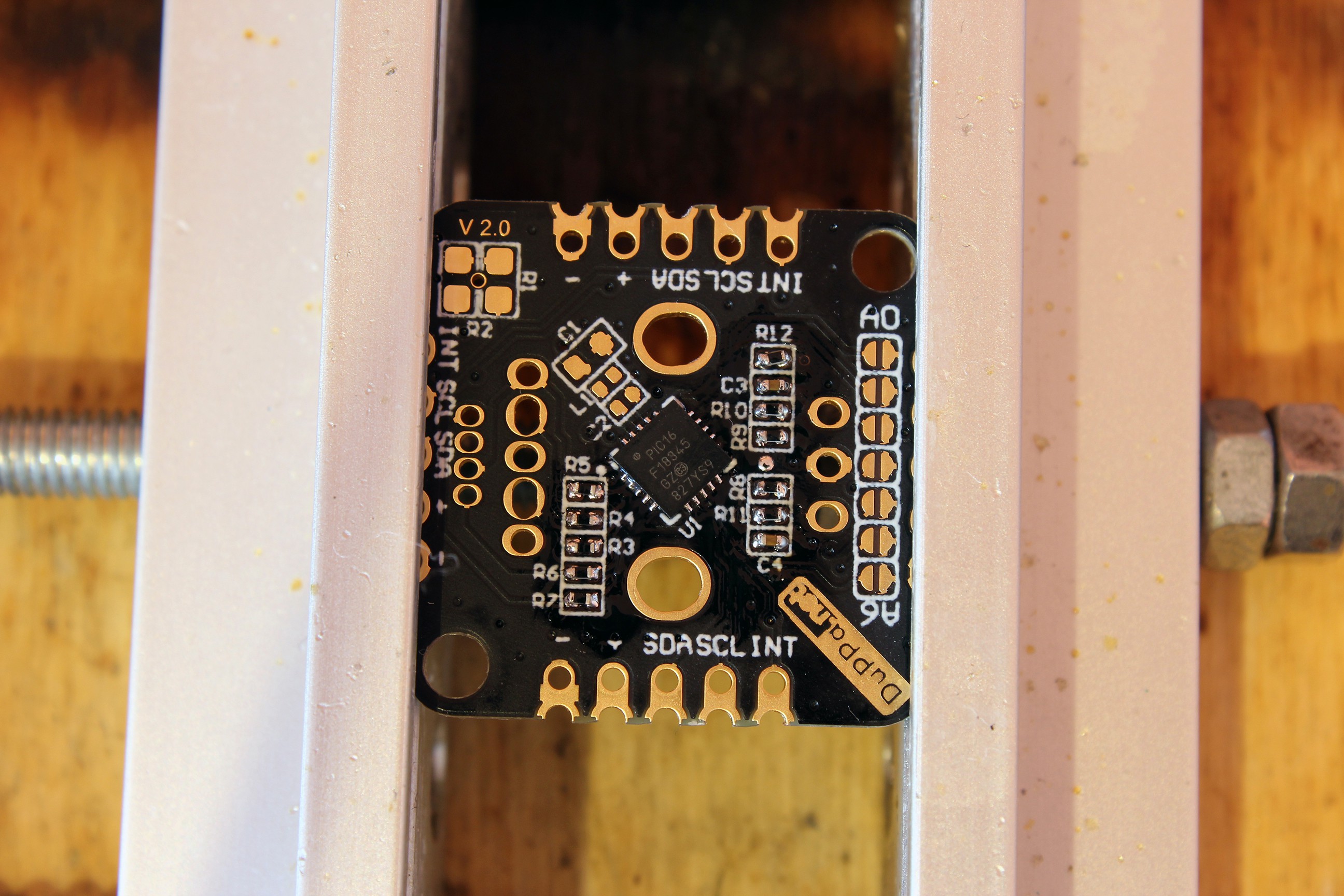
At this point, if you need you can solder the pull-up resistor and the connectors.
![]()
Pull-up resistor and connector are soldered -
6Prepare for flash the firmware
Now you have an I2C Encoder V2 board! But without the FW it is just a PCB with a MCU soldered.
In order to flash the FW inside of the MCU, you need a PIC programmer, i use the PICkit 3 but there are many types.
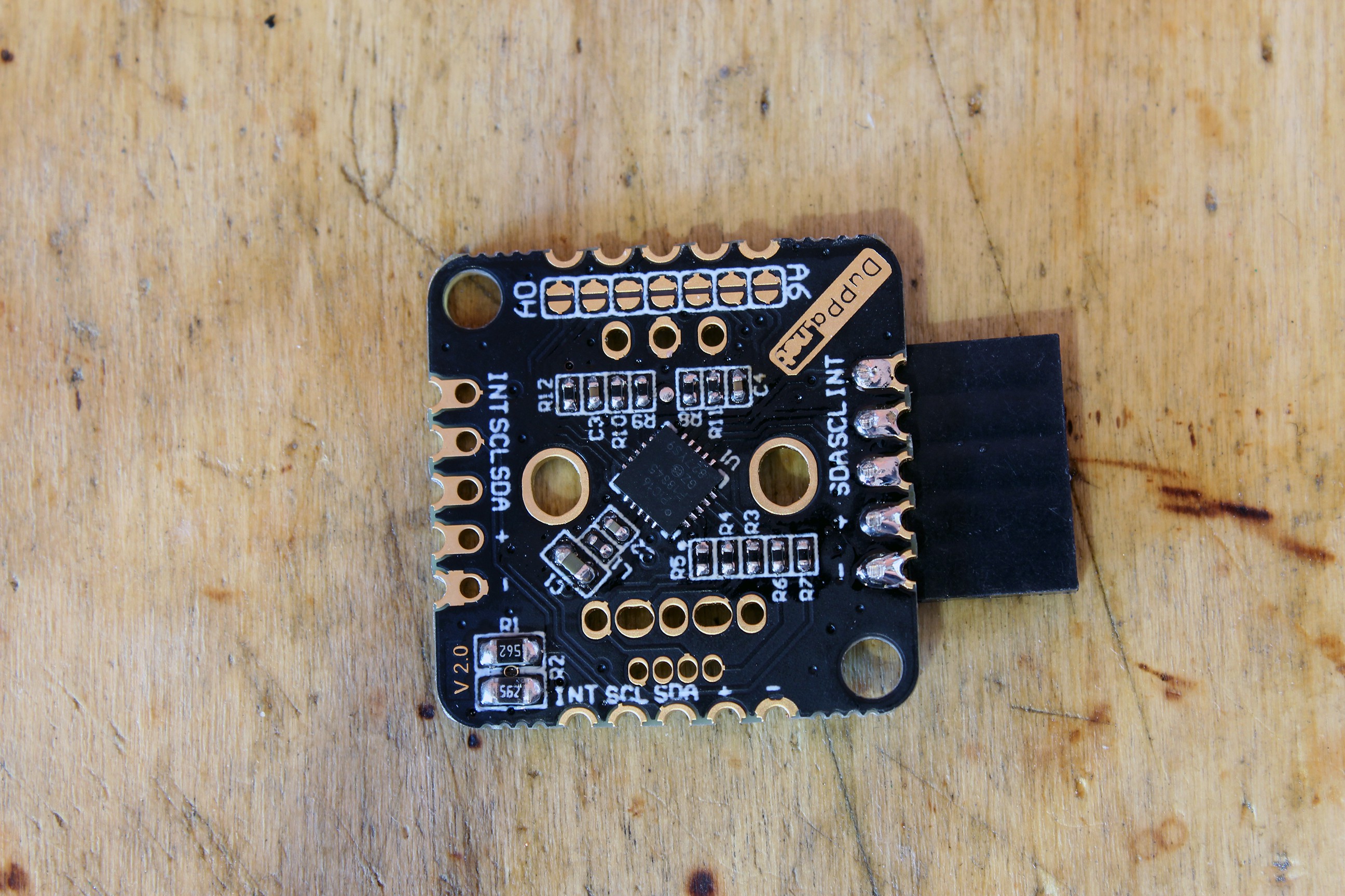
You also need to temporally solder a connector to connect the board to the programmer. The MCLR, PGD and PGC pins are 3 jumpers used for setting the I2C address.
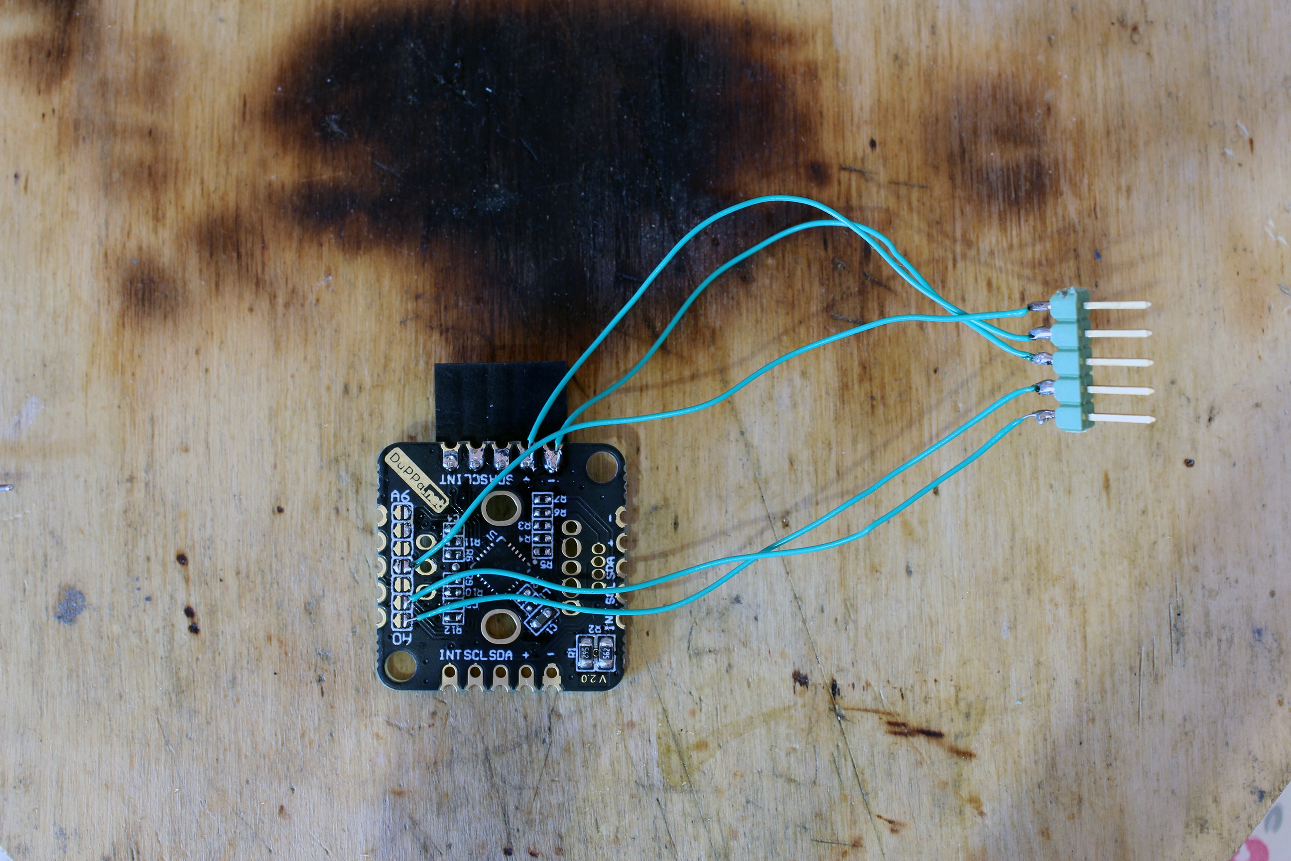
The PICkit needs 5 wires, in the following image the schematic of connection is shown:
![]()
Schematic of connections ![]()
First solder the power supply pins Pay attention not to short the jumper pins!
![]()
After soldering the data pins -
7Flash the board!
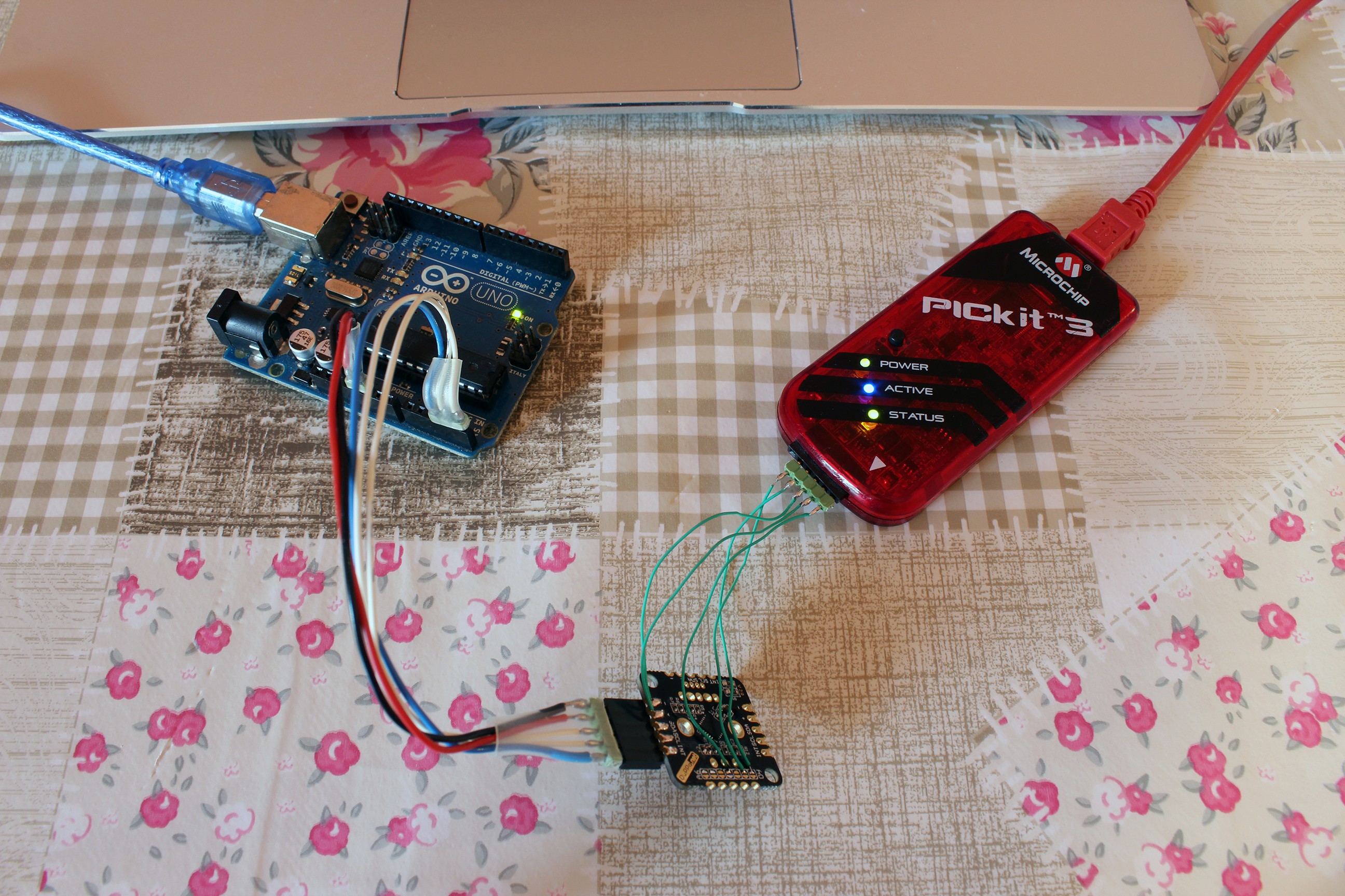
Now connect to the programmer and power on the board. In my case, i used the Arduino Uno for the power.
![]()
Connect the board to the power supply and to the programmer. At this point, you have to download the firmware and with the program MPLAB X IPE you have to flash the MCU.
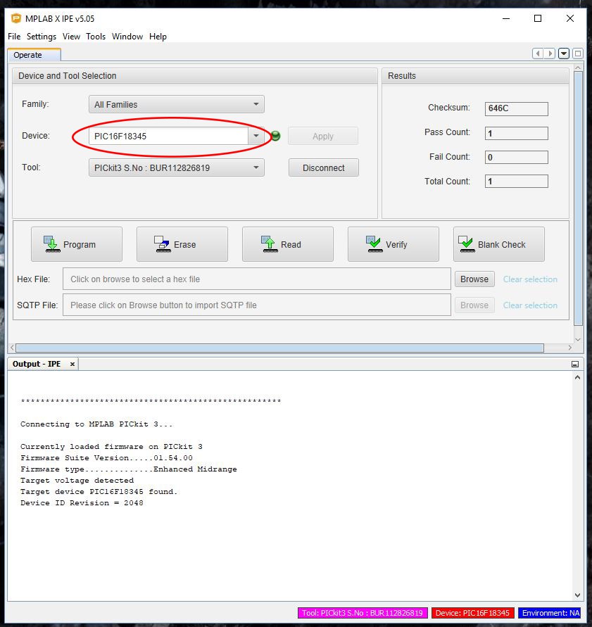
For doing that, you have to follow these steps:
![]()
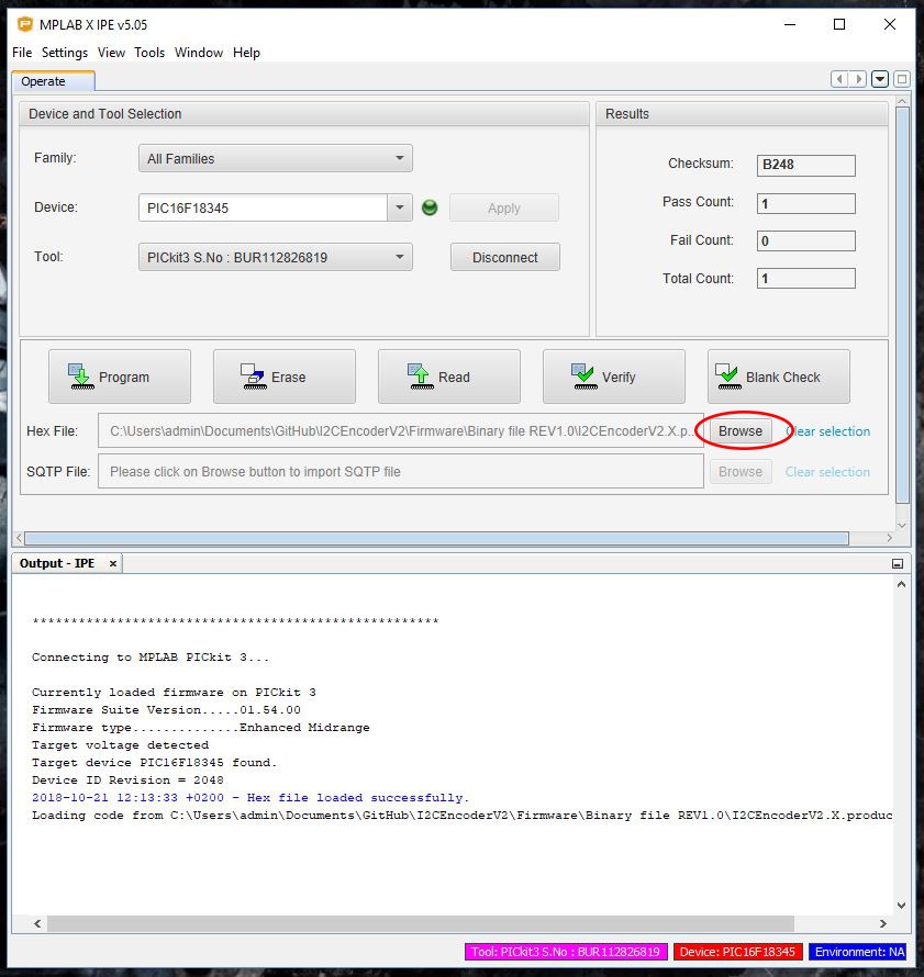
Select the PIC16F18345 ![]()
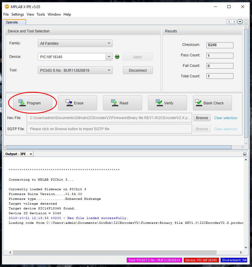
Click on "Browse" and select the .hex file of the firmware ![]()
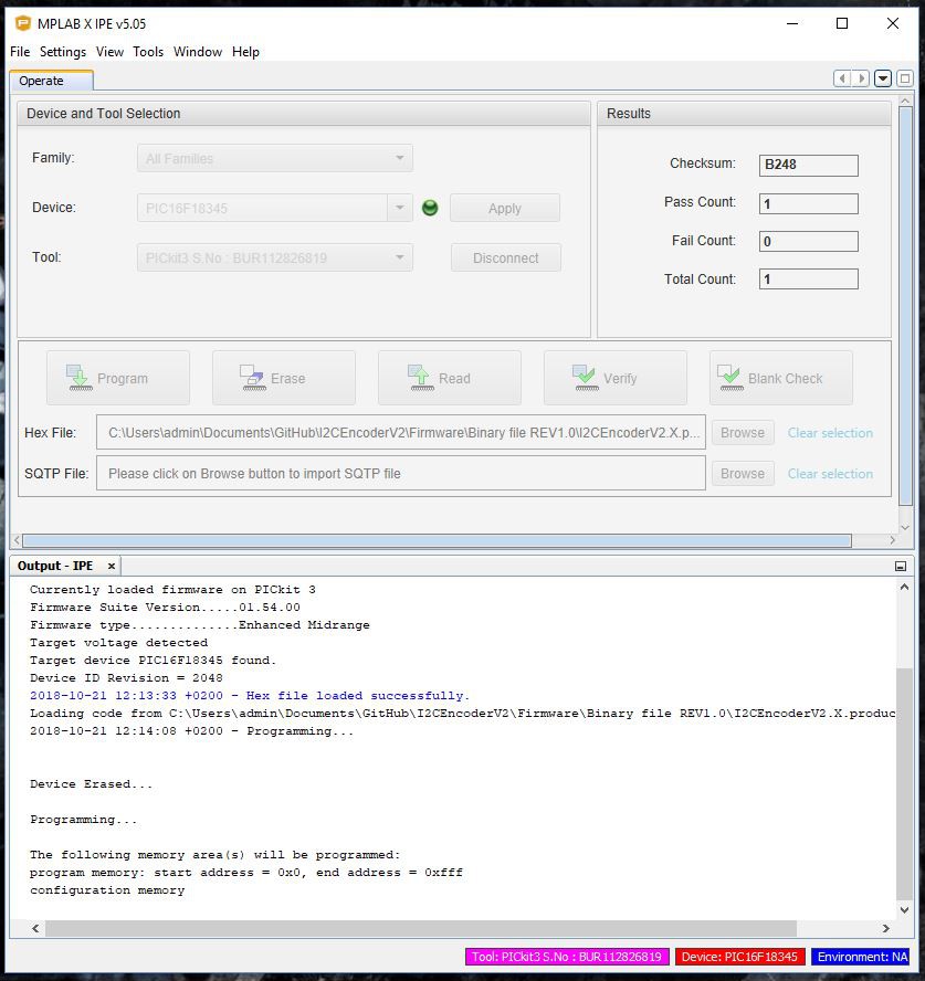
Click on "Program" for flashing the PIC ![]()
End with successfully programming. If the program fails, please check the following:
- Check if you have selected the right PIC
- Check that you are powering the board
- Check the soldering
When the programming is successful, you can remove the programming connector.
-
8End
At this point you have an I2C Encoder V2 board fully programmed and ready to be used!
Now you have only to set the I2C adress by soldering the jumpers and you have to solder your favorite rotary encoder.
I2C Encoder V2
Upgraded version of the small board for connect multiple rotary encoders on the I2C bus.


Discussions
Become a Hackaday.io Member
Create an account to leave a comment. Already have an account? Log In.