Saimon
-
New FW release!
09/20/2021 at 10:31 • 0 commentsI have made an update about the detection of the encoder rotation.
In the previous version for detecting the encoder steps and direction it was used the CLC feature of the PIC16F18345., this method works but sometime some errors can appear.
In the Mini version the detection is made in FW with the lookup table method, this way is very efficient and it make very few mistake. For this reason i have decided to use the same way also in the I2C Encoder V2. The CLC are still used but for debouncing the encoder signals.
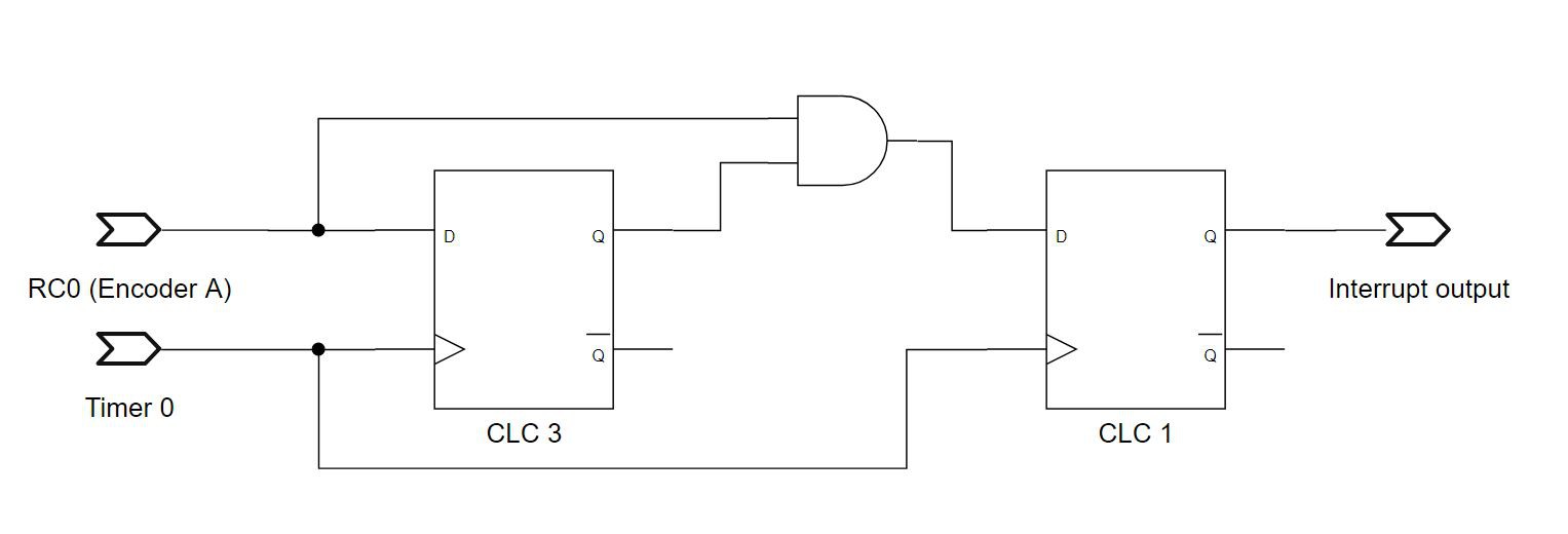
I have found this application note from Microchip where it use two CLC module and a timer for creating a robust debouncing circuit.Following the application note i have used the CLC 1 and 3 for the A signal and the CLC 4 and 2 for the B signal. The timer 0 is used for feeding the filp-flops
Here the logic:
![]()
The frequency of the timer 0 is configurable with the 8bit register ANTBOUNC, before this register was used for a similar function. The range is from 0.192ms to 49.152ms that correspond to a frequency 5200Hz to 20Hz. Each step correspond to 0.192ms.
The old functionality of the ANTBOUNC is removed, so there is no the delay when the direction it changed. This make the encoder more reactive.
-
OSHWA Certification
10/14/2019 at 20:50 • 0 comments![]()
This project got the OSHW certification!
https://certification.oshwa.org/it000004.html -
Version 2.1 is released!
08/07/2019 at 11:19 • 0 commentsOne year ago we release the I2C encoder V2, now is time to add some improvement!
We have made the I2C encoder V2.1 the new feature are the following:
Hardware changes:
- Added the jumper SJ8 for enable the pull-up resistor in the I2C bus.
- R1 and R2 are already soldered on the board with a 0402 footprint.
- Changed the value of R3 and R4 with 42.2
- Changed the value of R5 with 107
Firmware changes:
- Added the gamma correction feature.
- Added the unique code and the version registers.
- Added the possibility to enable/disable the I2C clock stretch.
- Added and extra delay after the detection of the double-push.
- Added the possibility to count absolute or relative steps
- Decreased of the 33% the power consumption.
- Changed the default value of ISTEP from 1 to 0.
![]()
Of course all the source file are available on GitHub
And the board is available on Tindie!
-
New Arduino library release!
03/13/2019 at 13:25 • 0 commentsThanks to several suggestions, especially codebeat-nl, we have updated the Arduino library:
https://github.com/Fattoresaimon/ArduinoDuPPaLibThe major update is the callback functionality with the I2C Encoder interrupts, and also the better integration with the Arduino IDE.
We will also use that repository for integrating the libraries of our future project!
-
Hidden feature on the push button detection
10/17/2018 at 11:59 • 0 commentsOn the I2C Encoder V2, it's possible to detect when the encoder switch is pushed, released and double pushed. But i have found out that i have accidentally introduced the functionality of detecting also a long push button press.
Lets check this Arduino code:
......
Encoder.writeDoublePushPeriod(50);  /*Set a period for the double push of 500ms */
......

if ( Encoder.readStatus(PUSHP)&& (Encoder.readStatus(PUSHR)==false)) {
        Serial.println("Long push!");
        /* Write here your code */
      }

      if ( Encoder.readStatus(PUSHP) && Encoder.readStatus(PUSHR)) {
        Serial.println("Fast push!");
        /* Write here your code */
      }

      if ( Encoder.readStatus(PUSHD)) {
        Serial.println("Double push!");
        /* Write here your code */
      }
In the code i'm setting a double push period of 500ms. This means that when i push the encoder the internal counter starts to count and after the 500ms i have an interrupt about the behavior of the switch.
if i have both the flag of pushed and released, means that in the 500ms i have pushed and released the encoder switch, so i have done a fast push.
But of i have only the flag of pushed, means that i have only pressed the switch ad maintained the switch pressed for at least 500ms. Then i did a long push! -
Project source file released
10/14/2018 at 20:12 • 0 commentsSince the project is complete we have released all the documents regarding the I2C Encoder V2.
On GitHub there are all the source files of the firmware and of the hardware!
Under the folder Firmware we have uploaded the hole MPLAB X project. While under the folder Hardware there all the production document, we have also added the 3D .STEP file.
The PCB project is available on CircuitMaker.
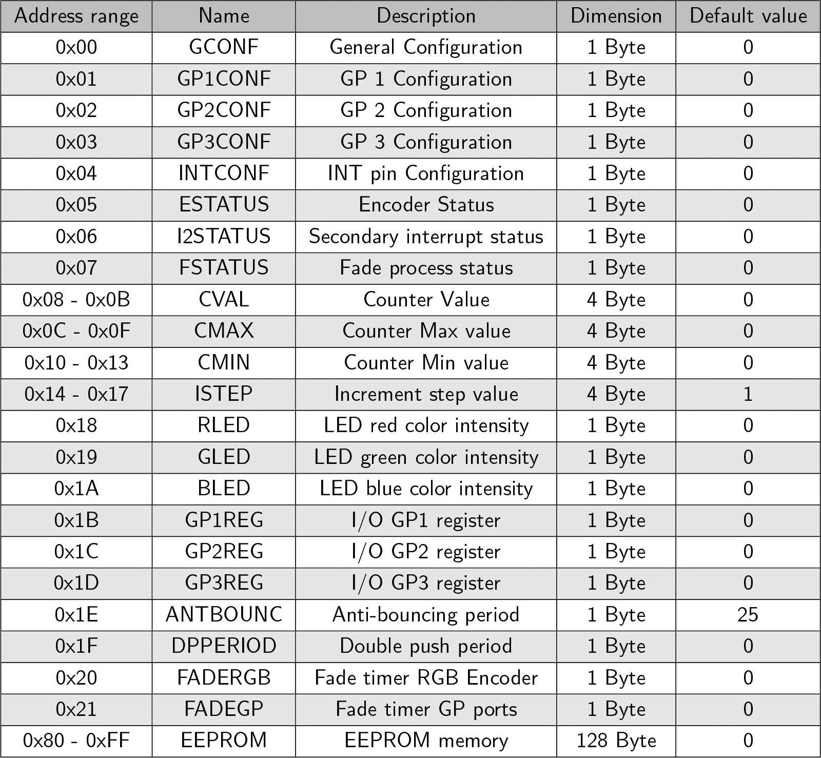
The final I2C register map is the following:
![]()
Respect to the original version we have changed several register, like the status registers, period register and the fade registers.
![]()
-
Final production version
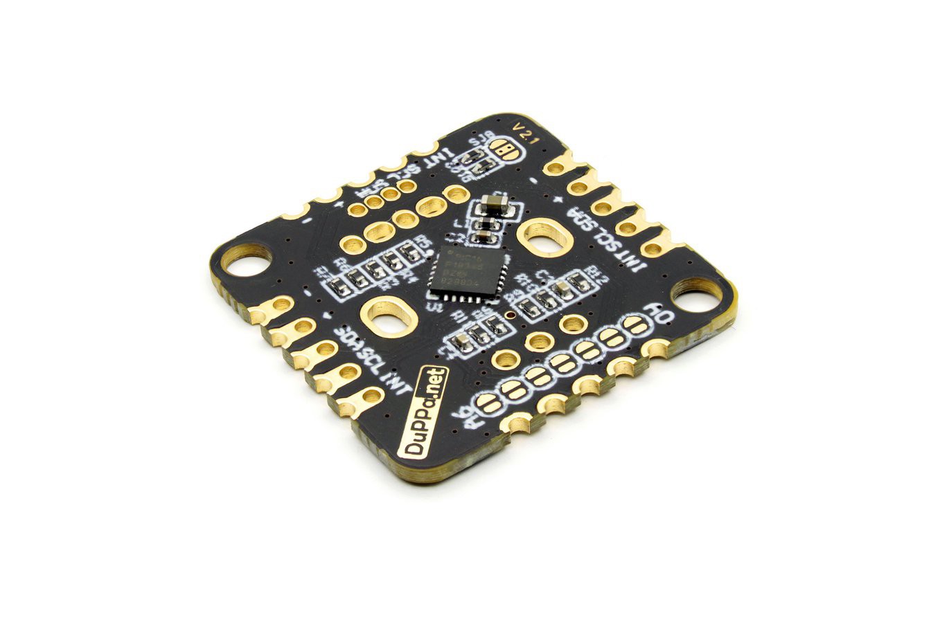
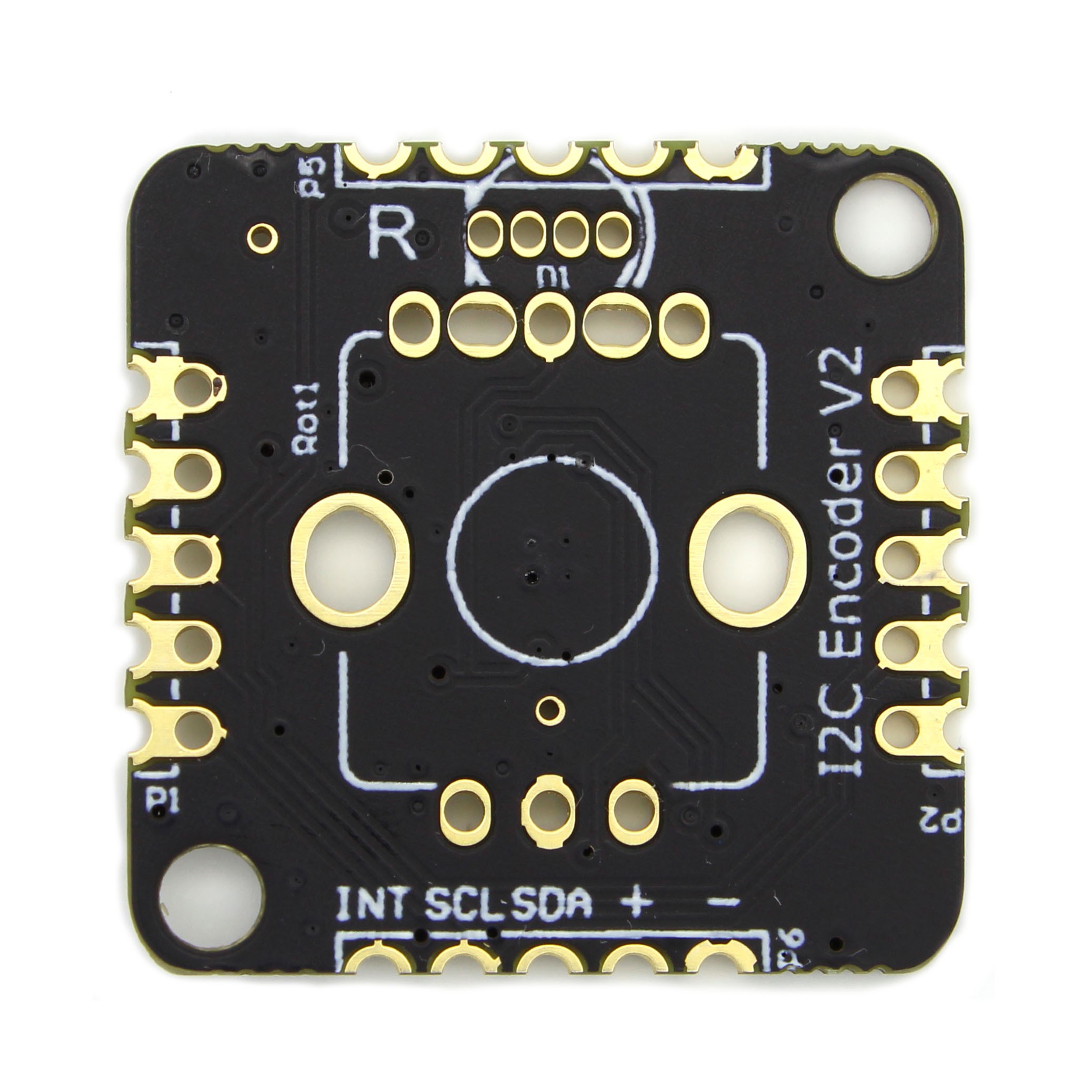
09/29/2018 at 16:32 • 0 commentsThe final version of I2C Encoder V2 is ready, we changed the color of the solder mask from blue to matte black.
![]()
![]()
Also the final version of firmware is completed, we will post soon on GitHub.
I2C Encoder V2 will be available in our Tindie store very soon, stay tuned!
-
Datasheet updated
09/14/2018 at 07:56 • 0 commentsWe have updated the datasheet with the all the feature, and we have added more descriptions. The datasheet is available on GitHub
We have changed the register status and we have added a configurable anti-bouncing register for the rotary encoder.
The firmware is still under progress. We will publish it once it is ready.
-
Feature updated
08/21/2018 at 20:44 • 0 commentsWe have updated the datasheet with the final feature. The datasheet is available on GitHub
There is an extra feature where it is possible to detect also a double fast push.
On GitHub, there is also the production file of the hardware
-
Auto fading feature
07/20/2018 at 06:32 • 0 commentsSome baker asked to add an auto-fading feature on the LEDs. And here we are!
We have added two new registers:
![]()
These two registers make it possible to set the speed of fading. FADERGB is about the RGB led of the encoder FADEGP is related to the GP pins. The value that you write inside is the step speed of the fading ramp, and it's in ms. If the value is 0, the fade feature is disabled. It meas that when the new value of PWM is written, it is immediately updated to the output.
The fading process starts when the FADE register is written. Fading process is complete according to the PWM value you have set. When the FADE PWM value is the same of the PWM value(it means that when fading is complete), an interrupt will be generated.
The following image shows the fading process according to the PWM value set.
![Example of the fading process]()
Example of the fading process Let's make an example:
At the startup, i write as:- RLED=0
- GLED=0
- BLED=0
- FADERGB=1
Now i write as: RLED=0xFF
And this moment, the ramp of the RLED starts and reaches the value 0XFF in 255ms. (the other LEDs remain OFF)
When the ramp rreaches 0xFF, i get an interrupt from the INT pin.After this, i write as: RLED=0x00. At this point, the fade ramp starts again and it will turn off the LED in 255ms, and an interrupt will be generated the end.
Here you can see an example:
In the video, every time when the encoders are rotated, the green LED turns on, while red LED (for RGB Encoder) and blue LED (for the normal Encoder) turn on when the thresholds are reached.
The yellow channel is the INT pin, while the other channels are the I2C bus. As you can see, there is no I2C traffic during the fading. There is I2C traffic only when i move the encoder and when the fading reaches the target value. I have uploaded the code example showed in the video in GitHub: https://github.com/Fattoresaimon/I2CEncoderV2
I2C Encoder V2
Upgraded version of the small board for connect multiple rotary encoders on the I2C bus.