andyknitt
-
Software Everywhere!
06/26/2014 at 15:48 • 1 commentSoftware Overview
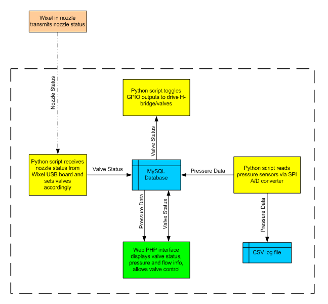
There's a lot of software that goes into this project. On the Raspberry Pi there are several Python scripts running, a MySQL database, and a PHP web interface. There is also C code running on the Wixels. Here is a basic block diagram that shows what's going on:
![]()
The heart of the system is a MySQL database that stores valve status (on/off) and pressure and flow information for each valve that's connected to the sytsem. This system is an extension of the technique explained here that allows web control of Raspberry Pi GPIO. In addition to web (LAN) control of the valves, we also want the simulated nozzle to be able to control them. To accomplish this, there is a script that constantly checks the desired status of the valves in the MySQL database and turns the valves on or off whenever a status change is detected (remember we are using latching solenoids so we supply a pulse when we want to turn a valve on or off). We can then have multiple programs or scripts reading and writing to the MySQL database as needed. There is the possibility that multiple programs could be writing conflicting values to the database. For instance, if an instructor uses his smartphone to turn a valve off while the simulated nozzle is trying to turn it on.
Eventually I'll get source code posted for everything, hopefully soon!
System Configuration
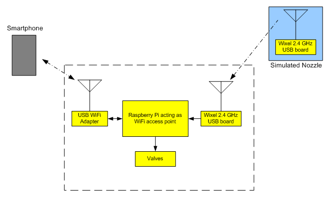
In a basic, standalone application, the Raspberry Pi can be configured as a WiFi access point to allow smartphones or tablets to connect to it. This configuration is shown here:
![]()
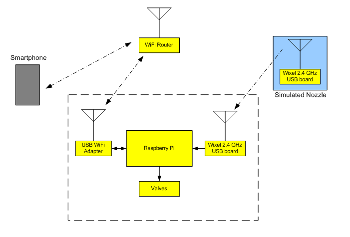
Another option is to have the Raspberry Pi connect to an existing wireless network created by an external wireless router. This could potentially allow greater range between the Pi and the smartphone devices, and also allows the connected smartphones to access the internet via the existing wireless network while still controlling the valves. Here is an illustration of this configuration:
![]()
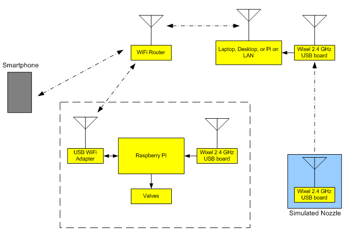
This configuration still requires that the valve control system be within wireless range of the simulated nozzle. The Wixel devices are very low power and don't have nearly the range of WiFi. This can cause problems, especially if firefighters are taking the nozzle into a metal building with the valve control system outside. Because we're using a MySQL database to track desired valve status, however, it's possible to have a remote computer on the same LAN edit that database. If a Wixel is connected to this remote computer, we can set up a remote receiver for the Wixel away from the valve control system, thus extending the range using WiFi. This is shown here:
![]()
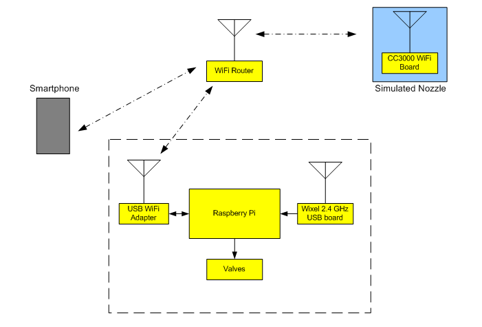
Eventually I'd like to replace the Wixel boards with a WiFi based board like this. Doing this would put everything in the system on the same WiFi network to allow the most flexibility. It also eliminates the need to make sure that the Wixel and WiFi systems are running on different channels to reduce interference. Multiple WiFi access points or WiFi repeaters could be added to the system as needed to improve range. Here's what that might look like:
![]()
-
Nozzle
06/21/2014 at 03:12 • 0 commentsA key part of this system is the simulated hose nozzle with a built in wireless transmitter. This simulated nozzle should have a look and feel similar to an actual firefighting nozzle, but block the flow of water in the hose. Remember that the goal of this system is to allow firefighters to take a fully charged (pressurized) hose line into a building but not allow them to flow water and damage the contents of the building. When they open the "bail" on this simulated nozzle, a valve will open to allow water to flow outside the building, thus exercising the pump and pump operator.
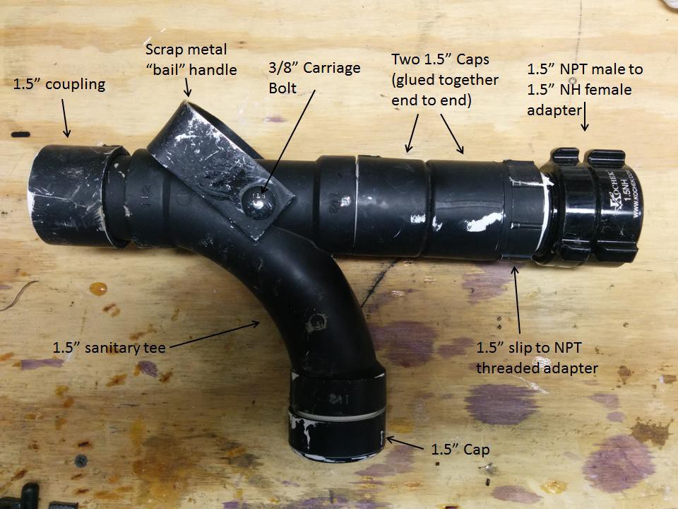
This proof of concept simulated nozzle is built mostly of 1.5" PVC pipe and fittings, along with a few other mechanical components. The electronics inside consist of a Wixel transceiver board, a cheap flashlight, a couple magnetic reed switches, and a holder for 2 AAA batteries. After assembly I spray painted it black just to make it look a little more like an actual nozzle. The picture below shows what parts were used for the exterior (the picture was taken after it took some abuse in a training exercise):
![]()
Most of these parts can be found at any local hardware or home improvement store, with the exception of the 1.5" NPT to NH threaded adapter. That piece adapts from tapered pipe thread (national pipe thread, or NPT) to fire thread (national hose thread, or NH) so that the nozzle can be attached to the end of a fire hose. NH threads use a gasket for sealing as opposed to pipe threads which must be sealed with pipe dope or teflon tape. This adapter can be purchased at any local firefighting supply company.
While several of the joints in this simulated nozzle are glued together, several others are left dry and fastened with drilled holes and bolts. This allows the nozzle to be partially disassembled for easy access to the interior parts. The pictures below show how the nozzle is taken apart to gain access to the battery holder and the other parts mounted inside. The nozzle "bail" handle is made out of a piece of scrap metal that I bent in a vise to the shape I wanted and then drilled to accept a carriage bolt. One of the round drill holes was filed square to accept the carriage bolt head, which forces the bolt to turn as the bail handle is moved.
![]()
![]()
The heart of this simulated nozzle is a Wixel programmable USB wireless module with an attached magnetic reed switch from sparkfun. The Wixel code is set up to simply transmit the status of the reed switch to a companion Wixel. The reed switch is activated by a magnet that is attached to the carriage bolt holding the scrap metal "bail" or activation handle of the nozzle. Here's a picture of the Wixel with a magnetic reed switch connected from one of the GPIO pins to ground:
![]() The Wixel is simply mounted to the inside of the nozzle body using double sided tape in the vicinity of the magnet on the carriage bolt. When the bail is actuated, the magnet rotates with the bolt inside the nozzle body. By fine tuning the location of the magnet and the Wixel, it's easy to get the reed switch to activate when the nozzle is "open" and deactivate when it is "closed". Power is supplied to the Wixel by two AAA batteries in a holder that's mounted in the "pistol grip" of the nozzle (the PVC sanitary tee). A slide switch has been superglued to the AAA battery holder to allow power to be turned on and off without having to remove the batteries. This battery holder and switch are covered by a PVC cap when in use so that the switch can't be accidentally deactivated as the nozzle gets drug, banged, and beaten around by ambitious firefighters.
The Wixel is simply mounted to the inside of the nozzle body using double sided tape in the vicinity of the magnet on the carriage bolt. When the bail is actuated, the magnet rotates with the bolt inside the nozzle body. By fine tuning the location of the magnet and the Wixel, it's easy to get the reed switch to activate when the nozzle is "open" and deactivate when it is "closed". Power is supplied to the Wixel by two AAA batteries in a holder that's mounted in the "pistol grip" of the nozzle (the PVC sanitary tee). A slide switch has been superglued to the AAA battery holder to allow power to be turned on and off without having to remove the batteries. This battery holder and switch are covered by a PVC cap when in use so that the switch can't be accidentally deactivated as the nozzle gets drug, banged, and beaten around by ambitious firefighters. ![]()
What about that flashlight I mentioned earlier? The intent is that when the simulated nozzle is "opened", it would produce a beam of light to simulate water spray, and also produce a spraying water sound. This gives students and instructors visual and audible cues that water is "being sprayed" even though it really isn't. In a long-term "elegant" solution, these visual and audible cues would be controlled by the same microcontroller that is transmitting the wireless data. In this "quick and dirty" proof of concept though, I did something much easier and "hackish" just to demo the idea. I took a cheap LED flashlight (the kind you find in the checkout aisle for $1.99) and connected another one of those magnetic reed switches across the switch contacts in the tail cap. I then stuffed the flashlight into the front of the nozzle using some water pipe insulation as a spacer. After adjusting the flashlight by moving it in and out away from the magnet on the carriage bolt, and by rotating it, I could get the light to turn on when the nozzle is "opened" and turn off when it is "closed". Like I said, kind of hackish, but it works as a demonstration.
![]()
So, how does it work? Quite well, actually! Transmitter range is similar to other low power 2.4 GHz devices. I would eventually like to migrate from using the Wixel to using a WiFi-based solution like the TI CC3000, but I had some Wixels on hand and they are easy to work with.
I'll post the code for the Wixels (along with all of my other code and design documentation) when I can get things organized a little better. If you have questions or suggestions for improvement, feel free to leave a comment!
-
H-Bridge Latching Solenoid Control
06/07/2014 at 21:28 • 4 commentsSince the brains of this project is a Raspberry Pi, we want to be able to control the valves from the Pi somehow. Since the valves are simple on/off valves, using the Pi's GPIO pins is a logical solution. However, there are a couple problems we need to address. First, the GPIO pins can only supply 3.3V at a relatively small current, while the DC latching solenoids that control the valves are 9V devices that pull more current than the GPIO pins can source. Another problem is that the DC latching solenoids require their supply polarity to be reversed to turn the valve off.
The solution to both of these problems is an H-bridge circuit. H-bridges are commonly used to drive DC motors in either direction by reversing the polarity of voltage being sent to the motor, and are commonly controlled by microcontroller pins. In this case we won't be driving a motor, but instead using the H-bridge to reverse the polarity of the voltage being sent to the DC latching solenoid. A schematic of the circuit I used is shown below.
![]() This can look a little confusing if you've never seen an H-bridge before, so let's step through it. The two terminals of the solenoid are connected to the S1A and S1B points. If we apply 3.3V to point H1B, that will turn on NPN transistor Q2 and allow current to flow from point S1A to ground. At the same time, that 3.3V also turns on NPN transistor Q3, which pulls point H1C low, which in turn turns on PNP transistor Q4. When Q4 is on it allows current to flow from the 9V supply to point S1B. So now we have current flowing from the 9V supply, through Q4 to the solenoid coil connected at S1B, through the solenoid coil to point S1A, and from S1A through Q2 to ground. The current path is complete, and the solenoid will activate, turning the water valve on. Since this is a latching solenoid, we only need to apply 3.3V to point H1B for about 500ms. This gives the solenoid enough time to fully activate and latch, and then we can remove power.
This can look a little confusing if you've never seen an H-bridge before, so let's step through it. The two terminals of the solenoid are connected to the S1A and S1B points. If we apply 3.3V to point H1B, that will turn on NPN transistor Q2 and allow current to flow from point S1A to ground. At the same time, that 3.3V also turns on NPN transistor Q3, which pulls point H1C low, which in turn turns on PNP transistor Q4. When Q4 is on it allows current to flow from the 9V supply to point S1B. So now we have current flowing from the 9V supply, through Q4 to the solenoid coil connected at S1B, through the solenoid coil to point S1A, and from S1A through Q2 to ground. The current path is complete, and the solenoid will activate, turning the water valve on. Since this is a latching solenoid, we only need to apply 3.3V to point H1B for about 500ms. This gives the solenoid enough time to fully activate and latch, and then we can remove power. To switch the solenoid in the other direction, we apply pulsed 3.3V to point H1D. The current path is then from the 9V supply, through Q1, out to the solenoid coil via point S1A, through the coil, into point S1B, and to ground through Q5. So we now have current flowing from S1A to S1B, which is opposite of when we applied 3.3V to point H1B. This switches the solenoid in the opposite direction, turning the valve off.
We can now use two GPIO pins from the Pi connected to points H1B and H1D of the H-bridge circuit to turn a single valve on and off.
I created a PCB that contains two of these H-bridge circuits along with some analog input circuitry for reading pressure sensors. This PCB connects via ribbon cable directly to the Pi. I'll post full schematics and PCB layouts (created in KiCad) eventually. In the mean time, if you have any suggestions for how to improve this circuit, by all means leave a comment to let me know!
-
Choosing Valves
06/07/2014 at 16:13 • 0 commentsFinding water valves that will work for this project is a bit of a challenge. Actually finding valves isn't a huge problem, but finding valves that are affordable is. Here are some of the requirements:
- Support 1.5" to 2.5" hoselines
- Support maximum pressures of at least 250 psi
- Support flows of 150-250 gpm without excessive friction loss
- Cost $100 or less
- Controllable via battery power
A motorized ball valve would be ideal for this project because it would allow the valve to be partially opened or closed. This feature can be used to deliberately introduce additional friction loss, which can simulate additional sections of hose. In addition, motorized ball valves tend to open and close slowly, which minimizes water hammer. However, motorized ball valves in the 1.5" to 2.5" range are very expensive.
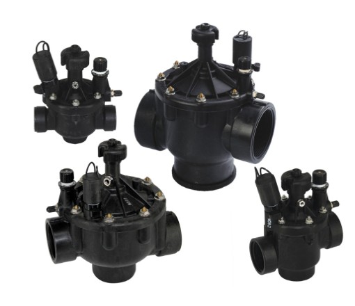
Instead, I ended up using a solenoid-controlled valve that was originally intended to be used in in-ground sprinkler systems. Finding a sprinkler valve that could handle the pressure and flow requirements was a challenge, since most sprinkler systems run at much lower pressures than fire hoses. However, the folks at www.sprinklersupplystore.com were great and helped me find the Toro P220 series of valves. These valves are rated to operate at up to 220 psi, which is a little short of my 250 psi goal. However, the 250 psi requirement is mostly just for robustness. Fire hoselines are typically operated at nozzle pressures of 50 to 100 psi. The discharge pressure at the fire truck will be greater in order to overcome the friction loss in the lines at high water flows (100 to 250 gallons per minute), but is still usually under 200 psi unless a very long run of hose is being pumped. Fire pumps are usually rated to go to 250 psi, but rarely do in actual practice. Since the P220 valves have a burst rating of 400 psi, I was ok with using them in this project even though they didn't quite meet the 250 psi operational requirement that I had hoped for. They'll still work to simulate 90% of typical fireground scenarios.
![]()
Solenoid valves are "on-off" valves. They can't be partially opened or closed. They operate by way of an electric solenoid that opens or closes a small passageway in the valve, and the water pressure in that passageway is then used to open or close the main waterway. In most lawn sprinkler applications the solenoid is operated by 24VAC, similar to what's used for HVAC controls. Apply 24VAC and the valve turns on, remove voltage and the valve turns off. Generating 24VAC in a portable, battery-powered device is certainly possible, but it makes life a little more complicated. Luckily, there are sprinkler control systems that are designed to run off of 9V battery power. The valves in these systems use a 9VDC latching solenoid instead of the 24VAC solenoid. A latching solenoid is a unique animal. When a 9VDC pulse is applied in one direction, the solenoid activates and latches. The 9V power can then be removed, but the solenoid will stay latched in that position. To switch the solenoid back to the other position, 9VDC is pulsed in the opposite polarity. This is perfect for battery-powered applications, since the solenoid does not continuously draw power when the valve is on, unlike 24VAC solenoids. To switch a 9VDC latching solenoid with a microcontroller, an H-bridge circuit is used. While this is a little bit complicated, it's not nearly as bad as having to generate 24VAC. A future post will detail the H-bridge design and how the valves are controlled.
I ended up using a 1.5" P220 series valve with a 9VDC latching solenoid for the proof of concept design. The part number is P220-26-96. While the 1.5" valve introduces some significant friction loss into the system while operating at typical fire flows, I'm using this to my advantage. By measuring pressure drop across the valve we can calculate flow, which is very useful for training. I'll write another post on friction loss and flow measurements later.
If anyone knows of a valve that would better meet the requirements for this project, leave a comment and let me know!


 The Wixel is simply mounted to the inside of the nozzle body using double sided tape in the vicinity of the magnet on the carriage bolt. When the bail is actuated, the magnet rotates with the bolt inside the nozzle body. By fine tuning the location of the magnet and the Wixel, it's easy to get the reed switch to activate when the nozzle is "open" and deactivate when it is "closed". Power is supplied to the Wixel by two AAA batteries in a holder that's mounted in the "pistol grip" of the nozzle (the PVC sanitary tee). A slide switch has been superglued to the AAA battery holder to allow power to be turned on and off without having to remove the batteries. This battery holder and switch are covered by a PVC cap when in use so that the switch can't be accidentally deactivated as the nozzle gets drug, banged, and beaten around by ambitious firefighters.
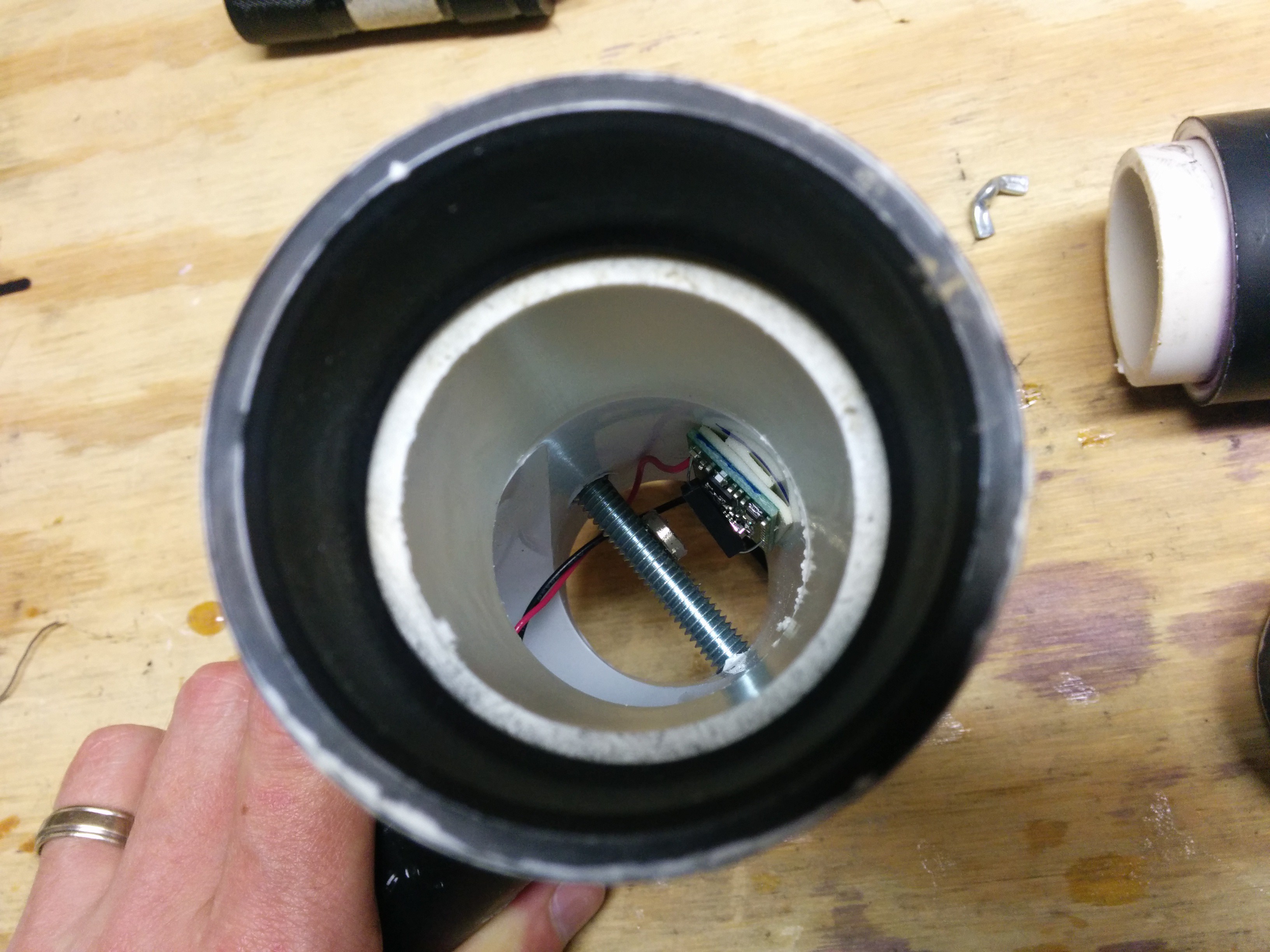
 This can look a little confusing if you've never seen an H-bridge before, so let's step through it. The two terminals of the solenoid are connected to the S1A and S1B points. If we apply 3.3V to point H1B, that will turn on NPN transistor Q2 and allow current to flow from point S1A to ground. At the same time, that 3.3V also turns on NPN transistor Q3, which pulls point H1C low, which in turn turns on PNP transistor Q4. When Q4 is on it allows current to flow from the 9V supply to point S1B. So now we have current flowing from the 9V supply, through Q4 to the solenoid coil connected at S1B, through the solenoid coil to point S1A, and from S1A through Q2 to ground. The current path is complete, and the solenoid will activate, turning the water valve on. Since this is a latching solenoid, we only need to apply 3.3V to point H1B for about 500ms. This gives the solenoid enough time to fully activate and latch, and then we can remove power.