Close
0%
0%

TyroBot

Easy to build and program walking robot. Powerful 32bit microcontroller, 7 servos, touchscreen display, and 3D printed parts

Similar projects worth following
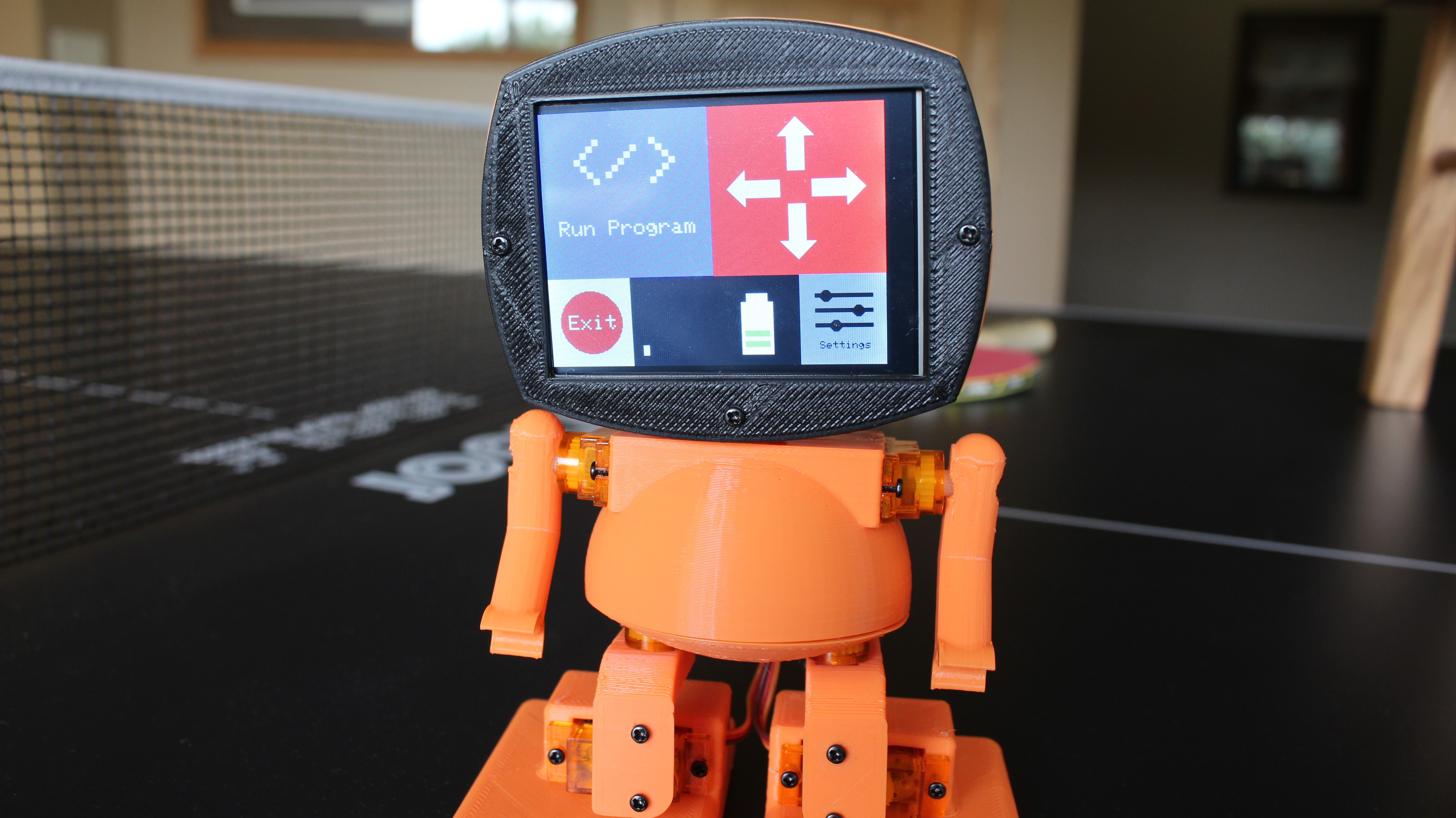
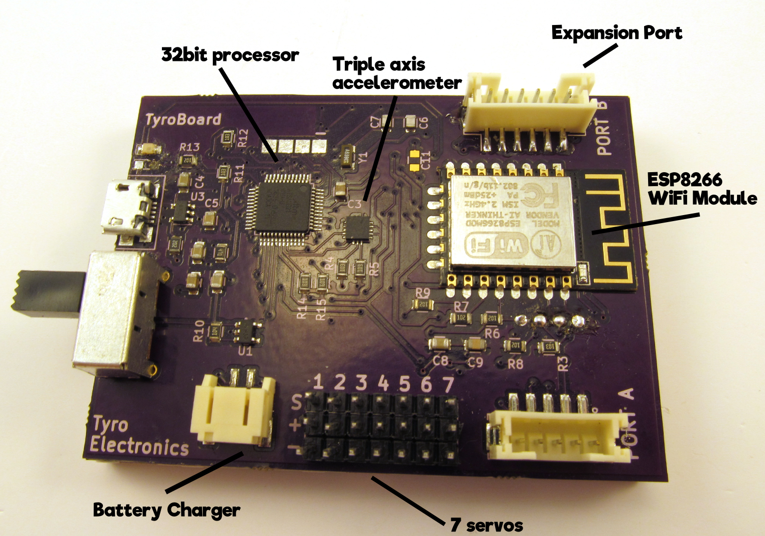
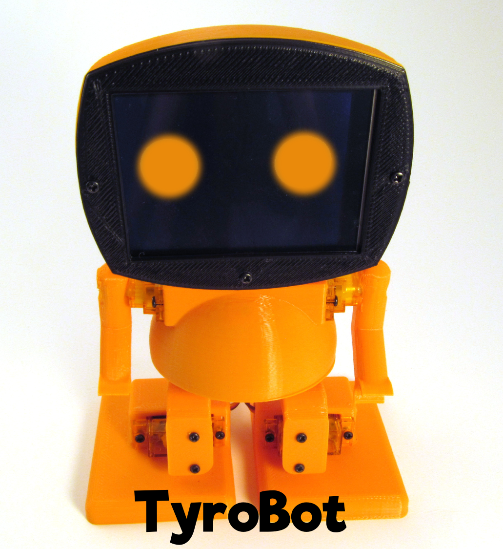
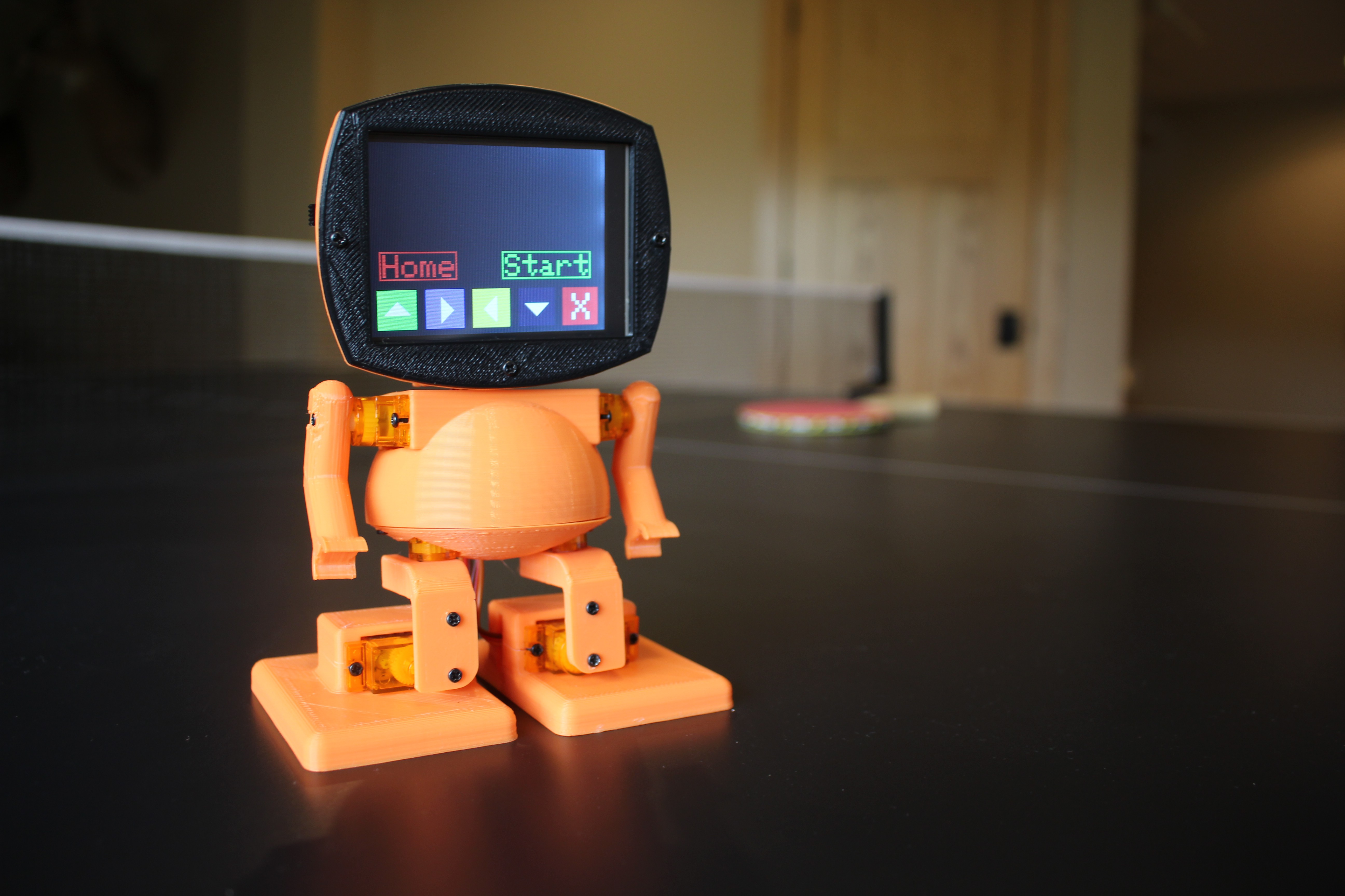
Learning to build and program robots is neither easy or cheap. TyroBot aims to change that. TyroBot is a fully functional humanoid robot built with inexpensive SG90 servos, 3D printed parts that can be printed on the smallest of beds, and a controller board using the low cost ATSAMD21 32 bit processor, esp8266 WiFi module, 3 axis accelerometer, battery charger, and 2.8in TFT touchscreen. TyroBot can be programmed right on his touchscreen face, or via the Arduino IDE using a special library. Want to build your own TyroBot? Please support our Kickstarter! https://www.kickstarter.com/projects/tyroelectronics/tyrobot-diy-humanoid-robot-kit

Project Goals

  • A robot that can walk in a straight line and not fall down.
  • make accurate turns.
  • Anyone can program it, from kids to Arduino users to pro C developers.
  • Uses a 32bit processor, the ATSAMD21G18A.
  • Entire robot can be 3D printed on a 100mm^3 bed.
  • Powered by a single cell lithium ion battery that is charged over micro USB.
  • Controlled wirelessly via WiFi on the ESP8266, hopefully peer to peer compatible so no wireless network is required.
  • Store multiple programs on board so you don't need to reflash every time you want the robot to do something different.
  • Self programmable; program on the robots face.
  • Uses an accelerometer to make walking gaits smoother and tells the robot if he has been pushed over.
  • Uses a 2.8in TFT display for running programs without a computer, configuration and more
  • 7 servos for legs, arms, and head.
How It Works

Read more »

  • 1 × TyroBot Board Custom circuitry magic
  • 7 × SG90 Servos
  • 1 × 11 3D printed parts
  • 1 × 1200mah lithium ion battery
  • 28 × 1.7M screws

  • Kickstarter Funded!

    tyspa09/02/2017 at 02:25 0 comments

    Thanks to everyone who purchased a TyroBot!

    We surpassed our goal by 150%!

    Over the coming weeks I will be busy 3D printing the parts and assembling the controller boards. 

    I will also be adding new features to TyroBot's software libraries, so if you have suggestions for cool new features let me know. There are also some exciting new hardware developments underway, so stay tuned! 

    --Tyler

  • 15 days left on Kickstarter

    tyspa08/17/2017 at 18:29 0 comments

    Hello everyone,

    A few new updates on TyroBot:

    • There are 15 days left on the Kickstarter, so if you want a TyroBot kit of your own, back now!
    • For a more detailed look on how TyroBot is assembled, check out my Instructable!
    • The design files have been updated, so now TyroBot can withstand drops from over 5 feet high. Walking off of tables will not ruin your day.

    Happy robot building!

    Tyler

  • Live on Kickstarter!

    tyspa08/02/2017 at 18:06 3 comments

    If you have ever wanted to build your own little humanoid robot, the time is now! I am crowdfunding a batch of TyroBots. Check him out on Kickstarter!

    You have pretty much two options: 

    • A complete kit including the parts 3D printed for you
    • A makers kit that lets you 3D print the parts yourself.

    TyroBot's brain is a controller board that hosts 7 servo motors, a rechargeable lithium ion battery, WiFi, a triple axis accelerometer, and 32 bit ATSAMD21 microprocessor. TyroBot is easy to control, whether that be right on the 2.8in touchscreen face, or with a simple arduino library.

  • Coming Soon to Kickstarter

    tyspa07/09/2017 at 19:03 2 comments

    Hello!

    Update 7/20/17:

    After almost 6 months of inactivity, (sorry, not much of a writer) I finally completed TyroBot and am making him into a kit that will sell on Kickstarter. It will launch in the next few weeks. More images, videos, and information about the new #TyroBot will be published then, for now enjoy the images.

    Also, congrats to @Craig Hissett on winning a $50 3D Hubs gift card for my survey!

  • TyroBot Alive

    tyspa12/12/2016 at 20:35 2 comments

    Before reading, please fill out this 6 question survey regarding my project to potentially win a $50 3D hubs gift card!

    Despite the clear lack of project documentation by me, progress on TyroBot is still underway albeit less due to school. Some main points on progress since Auguest:

    • TyroBot board v2 is functioning *almost* perfectly, but there are errors yet to be resolved.
    • TyroBot can walk in a straight line and turn, functionally equivalent to other 4 DOF bipeds.
    • Arm and head servos function properly, although no practical use, yet.
    • Accelerometer communication up and running, but forgot pull up resistors so board modification for v3 required.
    • SPI port working fine.
    • ESP8266 communication established, but concerns raised. I'll talk more on that later.
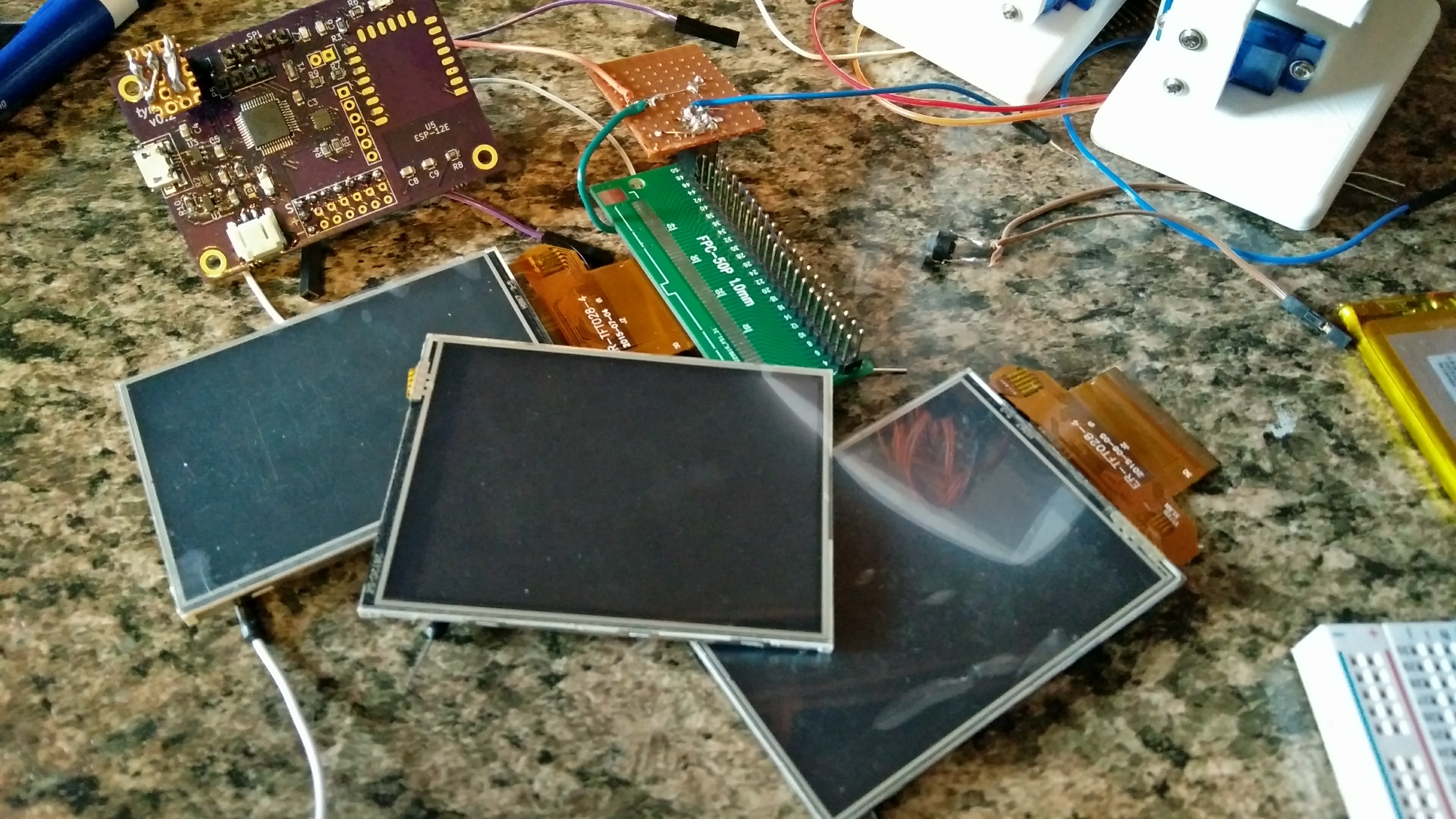
    • Touchscreen displays are a heap of trouble.

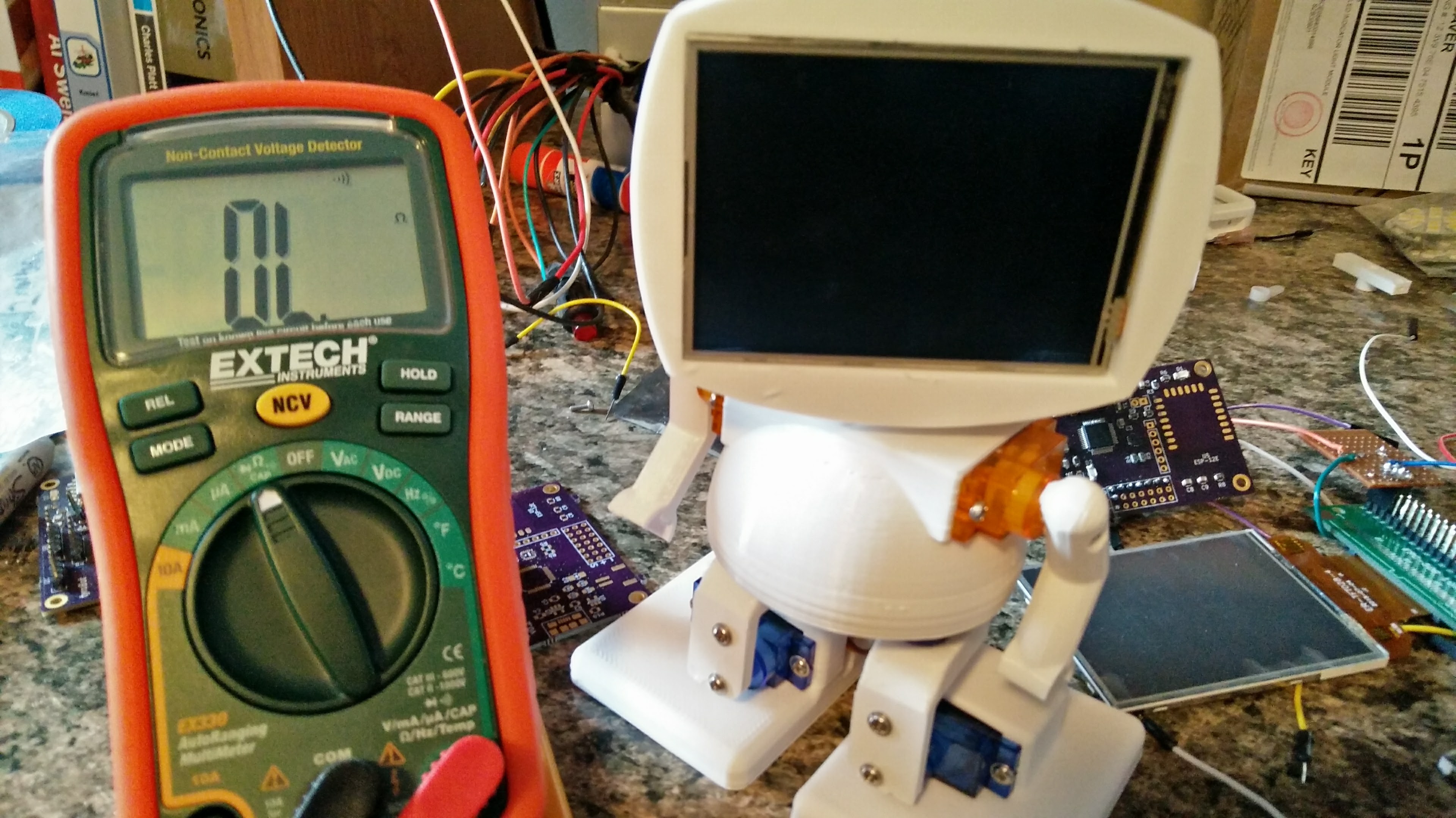
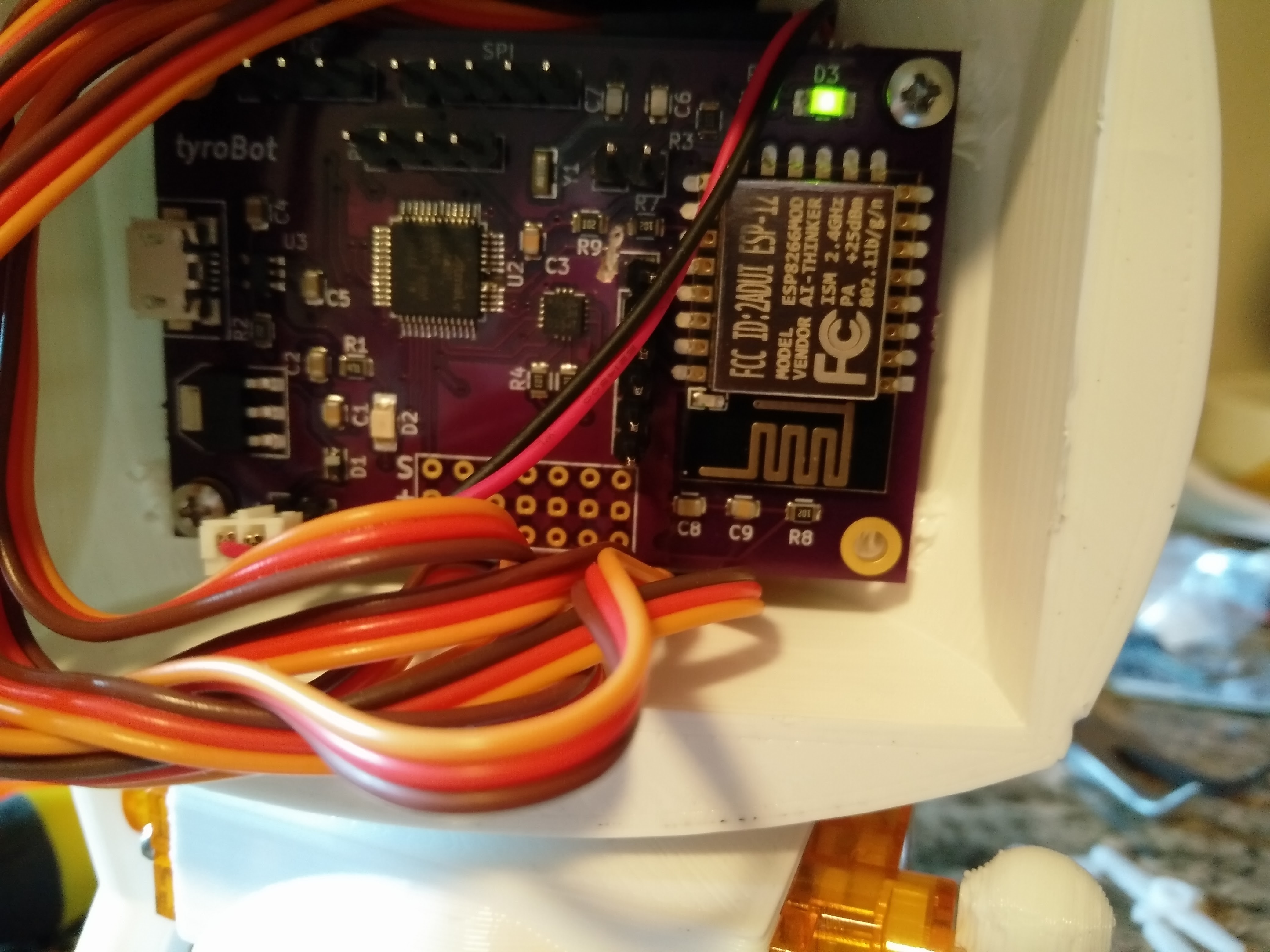
    With the board working and the robot moving around exquisitely, I decided to shift focus to the human user interface. In the above picture, TyroBot is aesthetically complete, but the touchscreen is yet to be operational and the electronics are seen in the background.

    One of the main goals of this project is usability. TyroBot in its name references the newbie. When complete, TyroBot will be printable on a bed of only 4"^3, and can be assembled with only a small screw driver. Other robots like this exist, but no robot will compare when it comes to software.

    One of the biggest advantages TyroBot will have to other robots is its software. TyroBot will not force the user to copy and paste code from stack overflow or be limited with an iPhone app. TyroBot will be programmed either from an IDE similar to Arduino (but better) or directly from the the display on the robot's face. My current challenge is getting the display to work.

    Instead of a static face like many robots, TyroBot's face will be a flat 2.8" touchscreen display. This will allow me or the user to change TyroBot's expression or robot settings without the need of an external computer or phone. I've convinced displays from ebay already on PCB's to work, and am in the process of designing TyroBot's rev 3 board to work with the displays out of the box. Instead of using the 40 pin ili9341 displays Adafruit uses, I will be using 18 pin variants like the ones found on the red ebay boards. If anyone has done this before, let me know, I need all the help I can get.

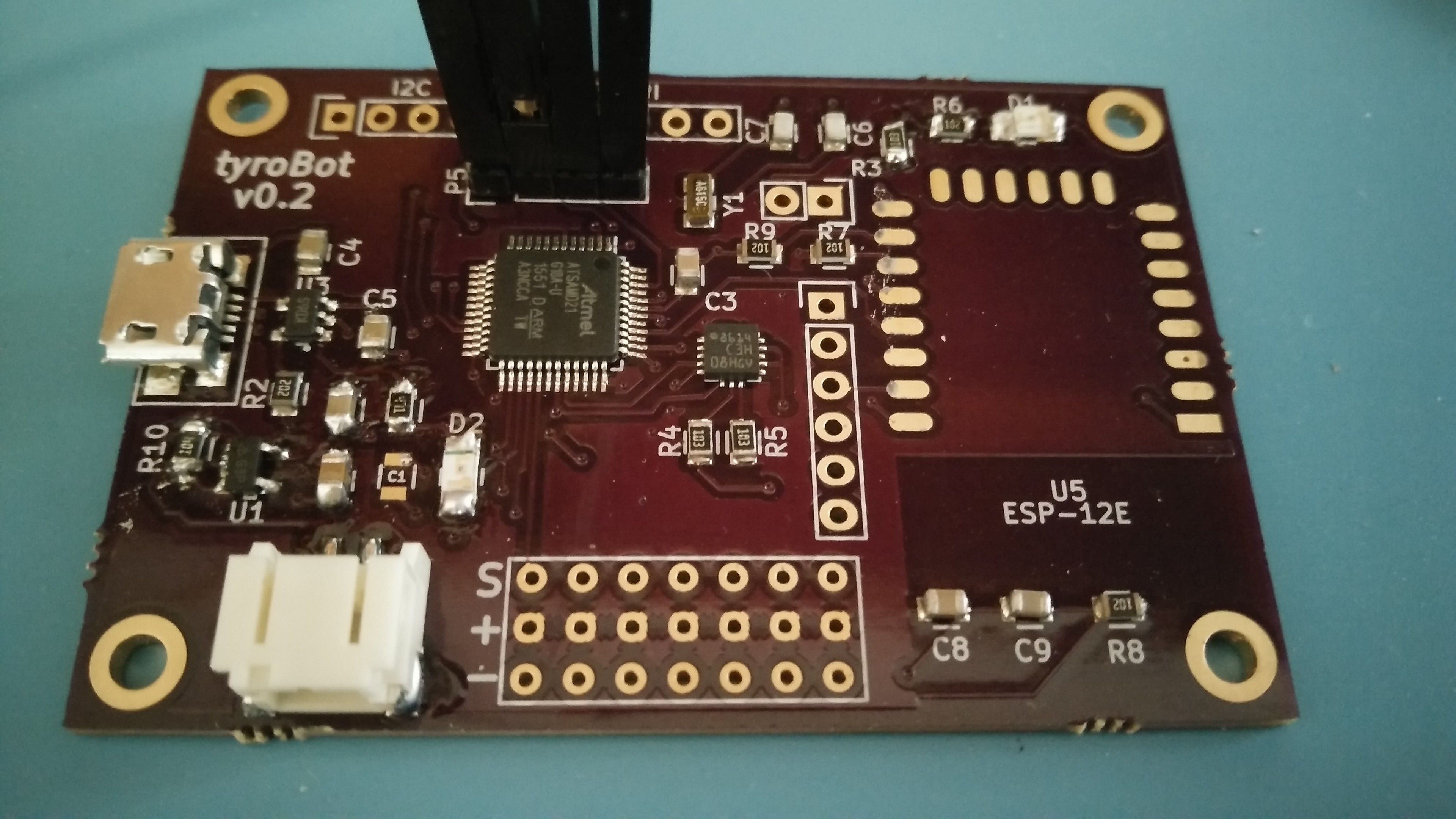
    1. Controller Board v0.2

      tyspa08/22/2016 at 12:49 0 comments

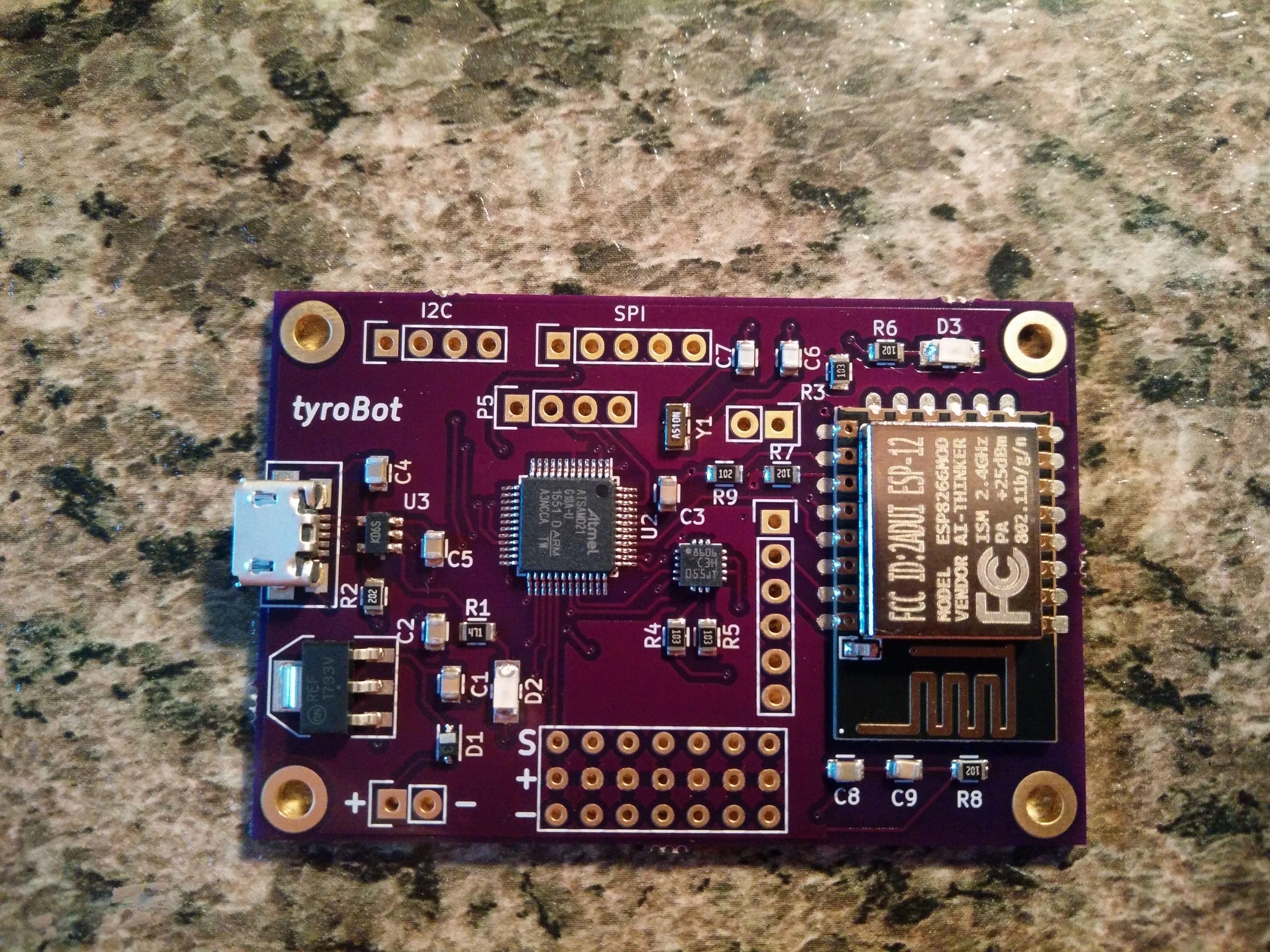
      Over the weekend I assembled the newest version of the controller board and ran some tests. The ESP8266 circuit remains unchanged from version 1, so I didn't solder in a module just in case there is something fatally wrong with another part of the circuit.

      The new regulator circuit works like a charm, the huge voltage drop found in the previous regulator is no longer present meaning longer operation times for TyroBot. The charging circuit appears to work, however I have not yet complete charged a dead battery to full capacity.

      I am still in the process of programming the ATSAMD21 and so far so good. Like I said in a previous log I don't have a Atmel ICE or J-Link debugger/programmer so I am attempting to hack the bootloader/firmware on the chip with STM's programmer, the ST-Link. Normally you would flash the chip in Atmel Studio, but the ST-Link is not compatible with the software. Instead, I have been using OpenOCD as the software and am semi-successful. I am able to communicate with the chip, but still unable to get Atmel's or Arduino's bootloader flashed. After a few hours of failed attempts I gave up and just ordered a J-Link.

      I'm pretty sure the problem is my sketchy programming setup and not the board itself. We will see in a week or two.

    2. Prototype Complete (well not quite)

      tyspa08/13/2016 at 22:24 3 comments

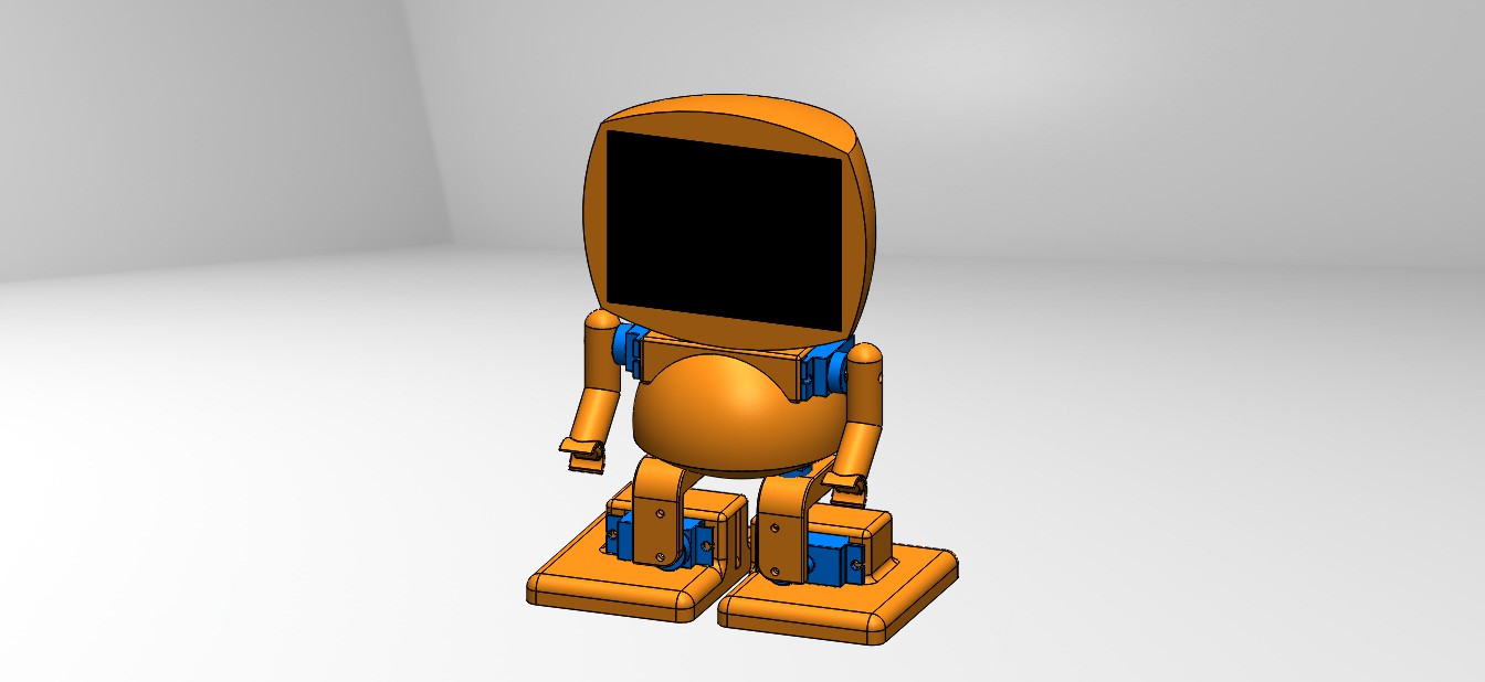
      While waiting for the v0.2 PCBs I finished 3D modeling the remaining pieces of the robot, including adding a head servo, controller board standoffs, and battery holder.

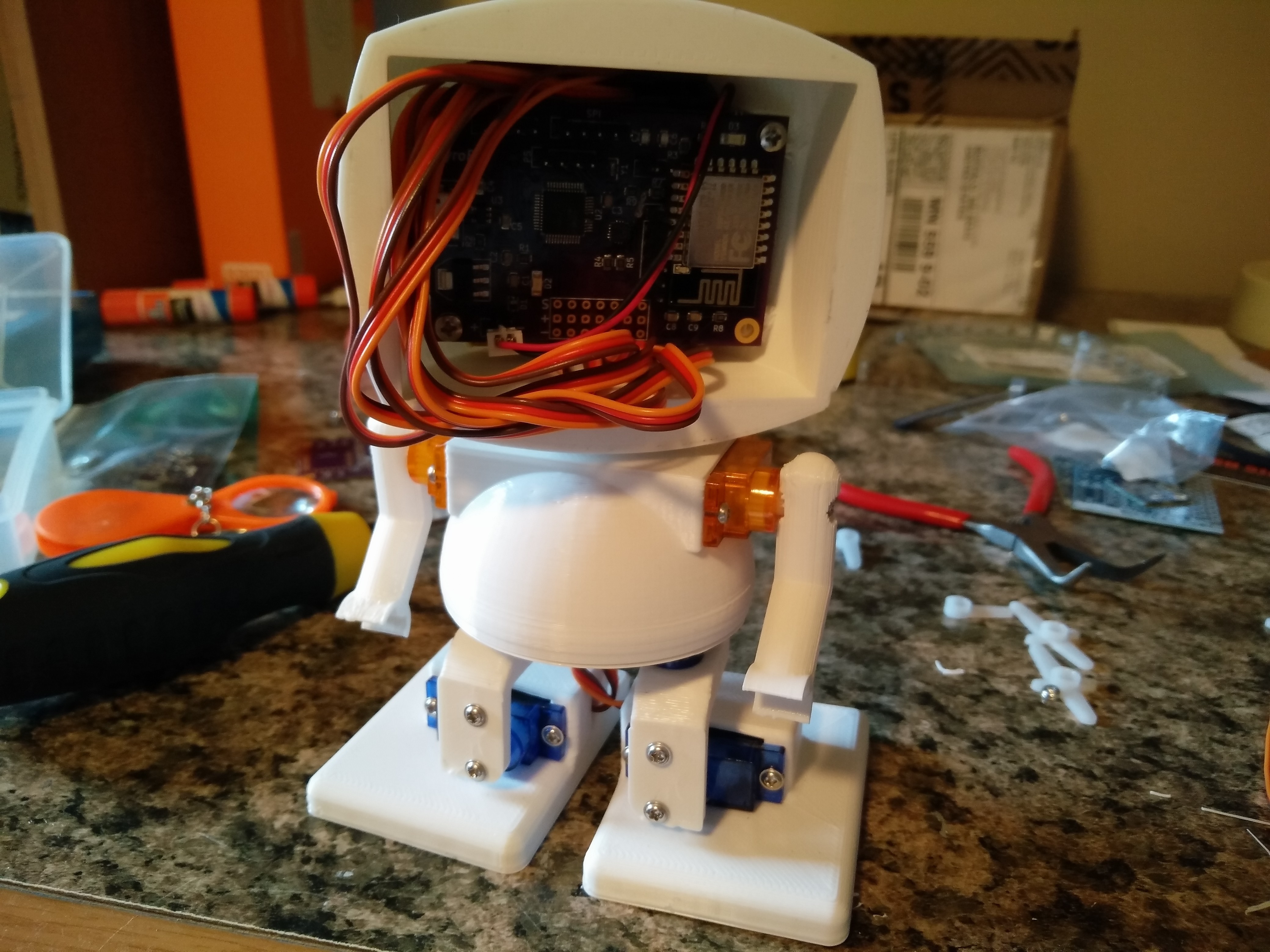
      The battery and controller board fit inside the head with plenty of room to spare. I don't have a display yet but right now getting the robot to walk around is a little more important. Once TyroBot is up and walking i'll add the display either as a separate PCB or part of the 3rd revision of the controller board.

      The controller board above can't really do anything, as only the esp8266 and the power circuit are functional. The PCBs and components should arrive around August 20th so shortly thereafter we *should* have a working robot.

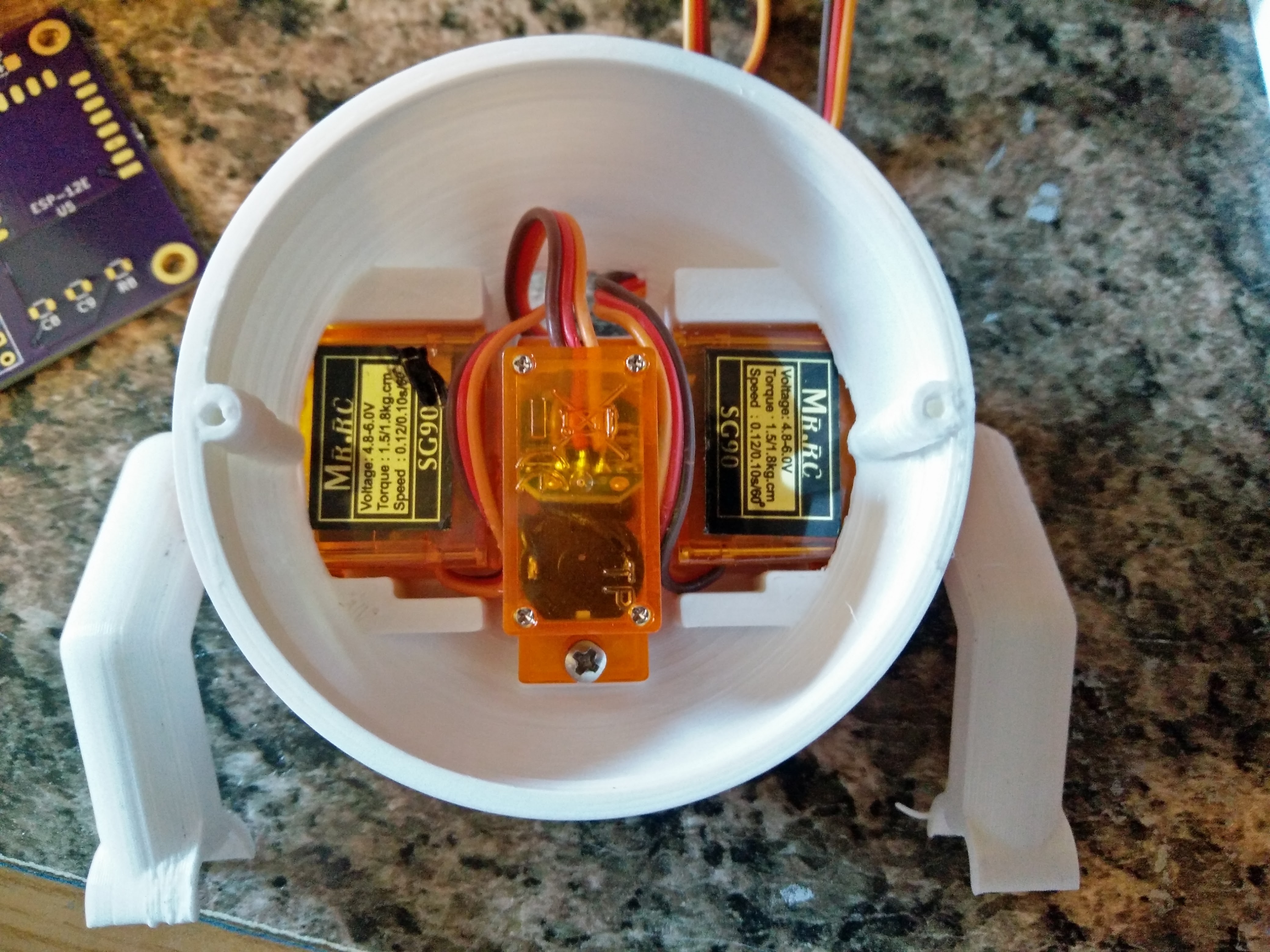
      Here we have a look inside the torso. Not very much room left for wires, so they will be routed through the back and into the head.

      Now to wait for the new controller board so I can start writing TyroBot's firmware.

    3. Controller Board fixes and v0.2

      tyspa08/04/2016 at 01:26 2 comments

      Over the past weeks I have been working with the board mentioned in the previous log. Unfortunately it didn't work 100% correctly (as expected with my talent).

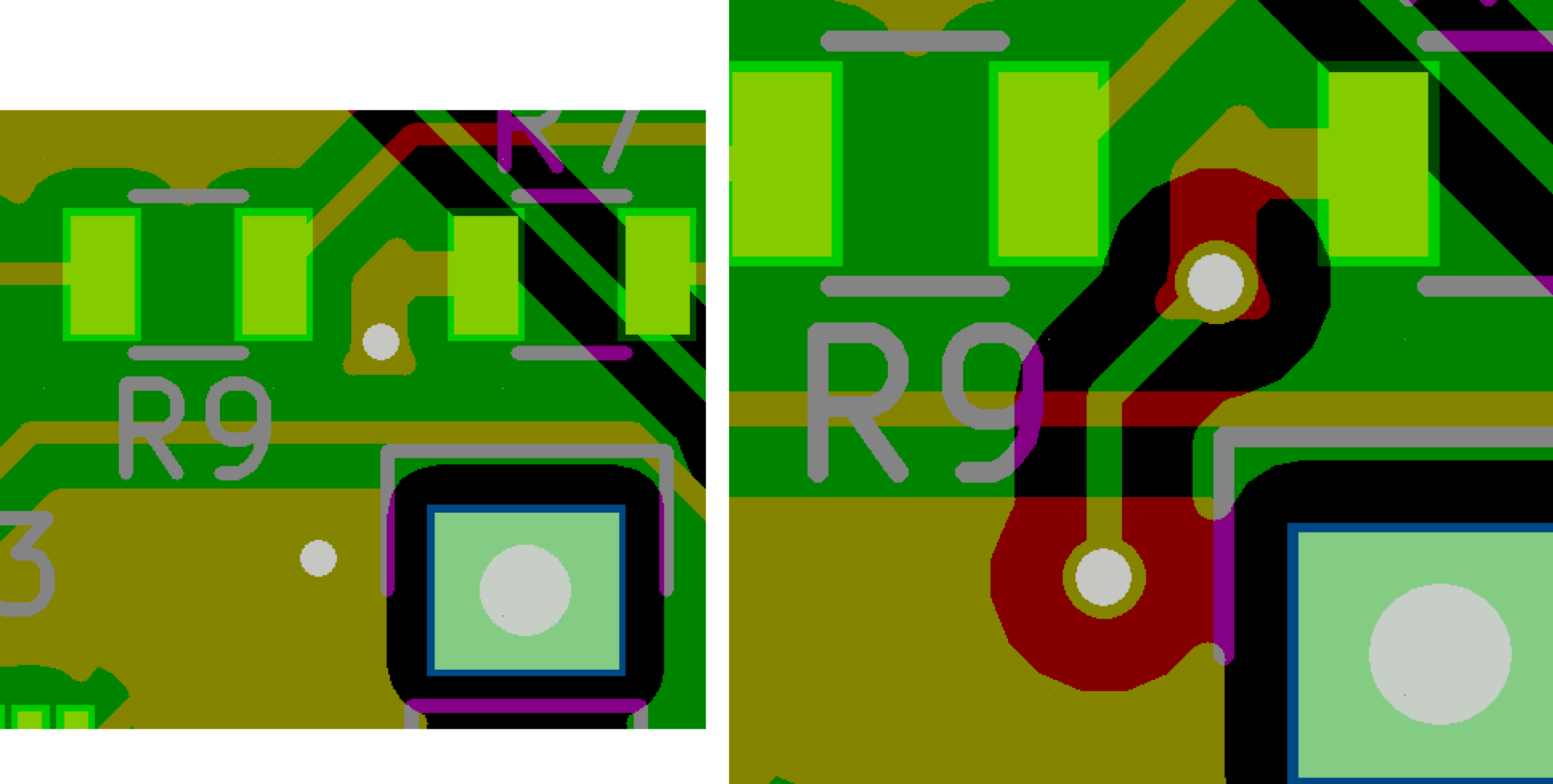
      First there was the minor problem of the VCC rail directly shorted to ground. As you can see on the right the DRC didn't notice that the back copper fill hadn't been recently done. Thanks KiCad. Luckily I didn't ruin any components and the battery was connected to a diode. I was able to fix the board by destroying the trace with a razor blade. I also cut a trace from the ATSAMD21 to the esp8266, so the ATSAMD21 is unable to reset the esp8266 automatically. This is okay for testing purposes.

      With that out of the way, I ran some basic tests.

      • The power regulator worked great, but the voltage drop is too high. After a while the board will fail to power up even though the battery is still quite full. On the next board I will use a different regulator, and maybe drop the protection diode that saved the board earlier.
      • The battery charging circuit worked as expected.
      • I was unable to connect to the ATSAMD21. This I *believe* is due to the fact I left two ground and one VCC pin disconnected with the false assumption that they were connected internally. I tried soldering wire to the pins but they were right next to each other in the middle of the chip. I accidentally broke the ground pin while trying to solder. Very frustrating.
      • I took a few days off to cool down from the above and played Pokemon Go.
      • Since the ATSAMD21 is nonoperational, I was unable to test the accelerometer. It should be fine since all I did was copy the Adafruit breakout board schematic.
      • The esp8266 booted up and worked perfectly, once I realized my FTDI breakout had the TX and RX swapped. I unintentionally swapped them twice, creating a double negative and connecting TX to TX and RX to RX.

      TyroBot Board v0.2

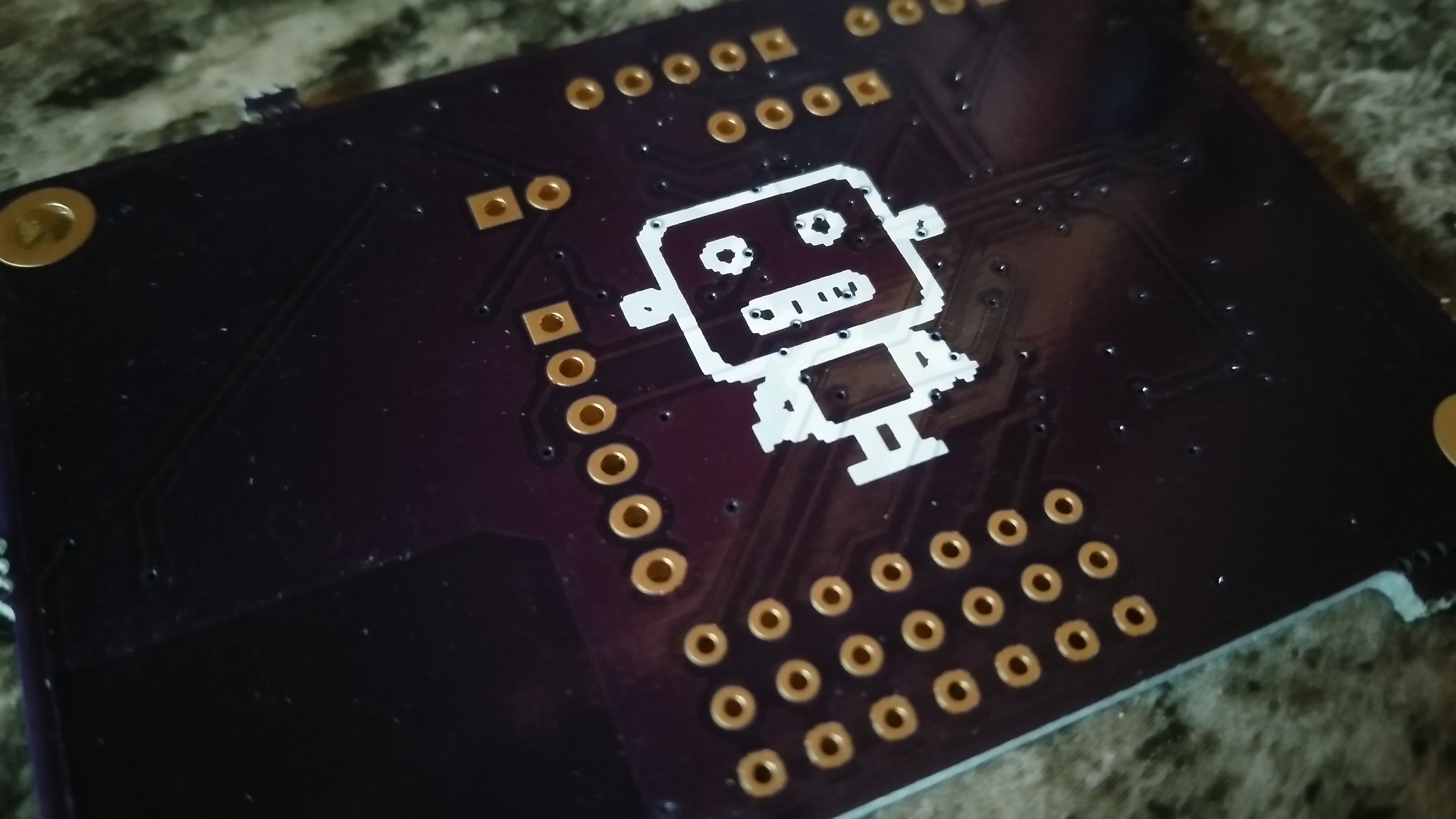
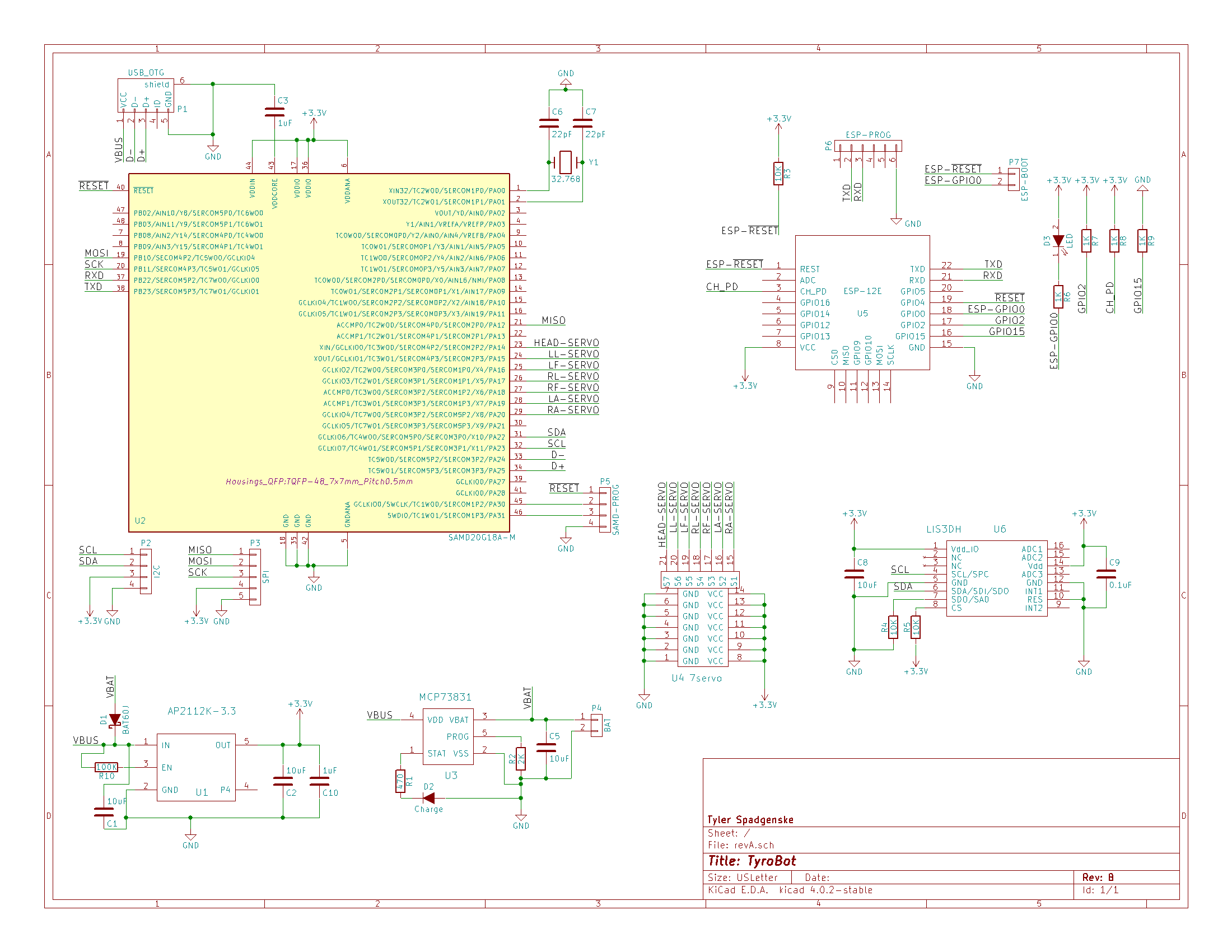
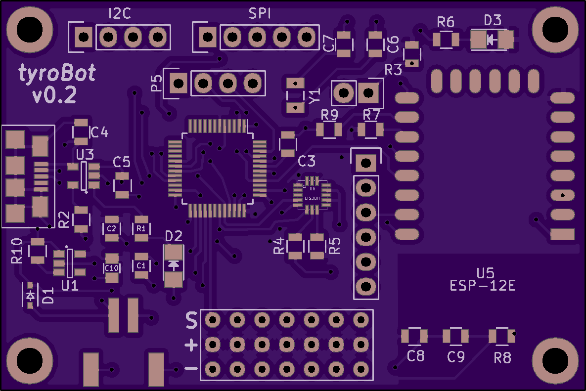
      I corrected all the mistakes mentioned above, including switching the 3.3v regulator to AP2112K-3.3. Doesn't provide quite as much current output but should be fine. I also replaced the two pin battery connector with a JST connector. The scematic and board render are below, and the design files are on Github, so if you see any more stupid mistakes be sure to let me know.


      While I am waiting for the new boards, I hope to get the 3D models in working order running off a ATMEGA328 so I am not wasting time waiting for parts.
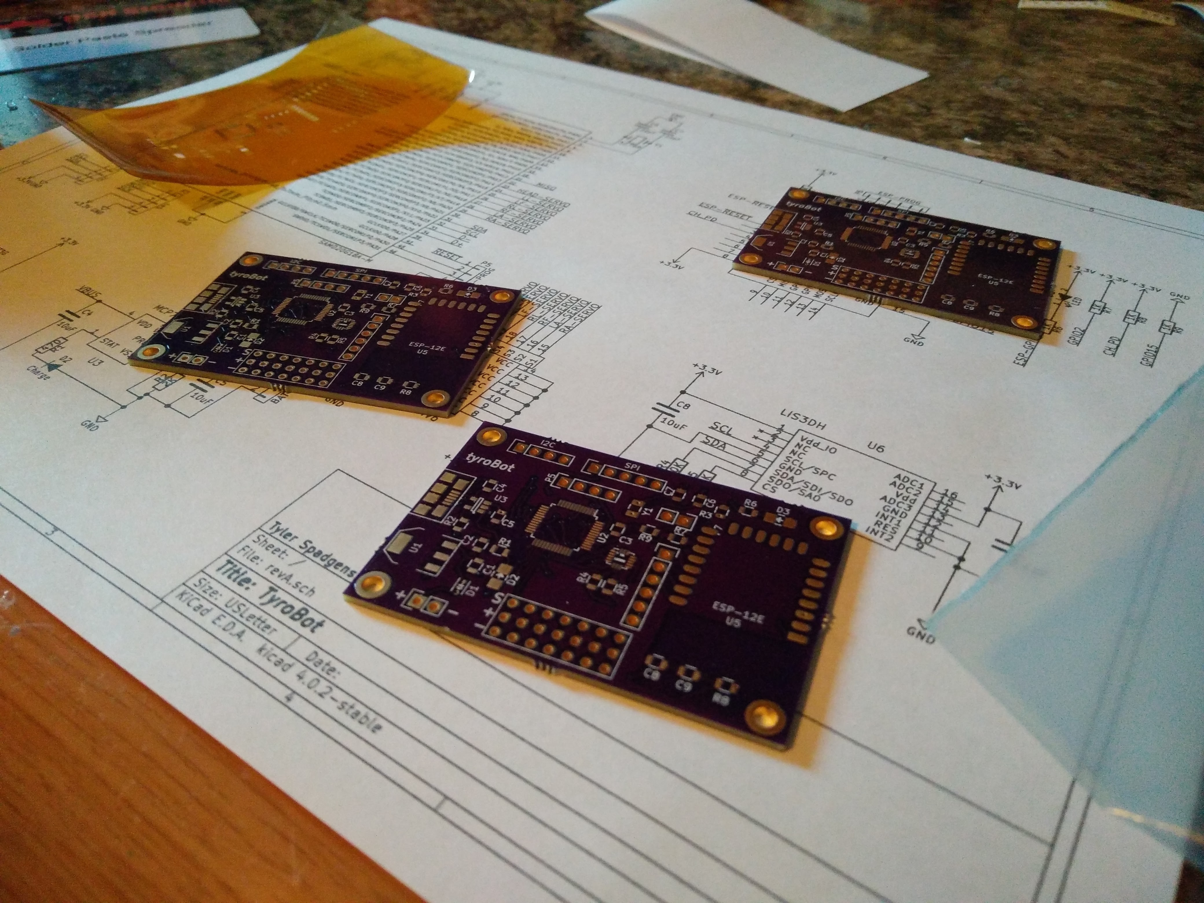
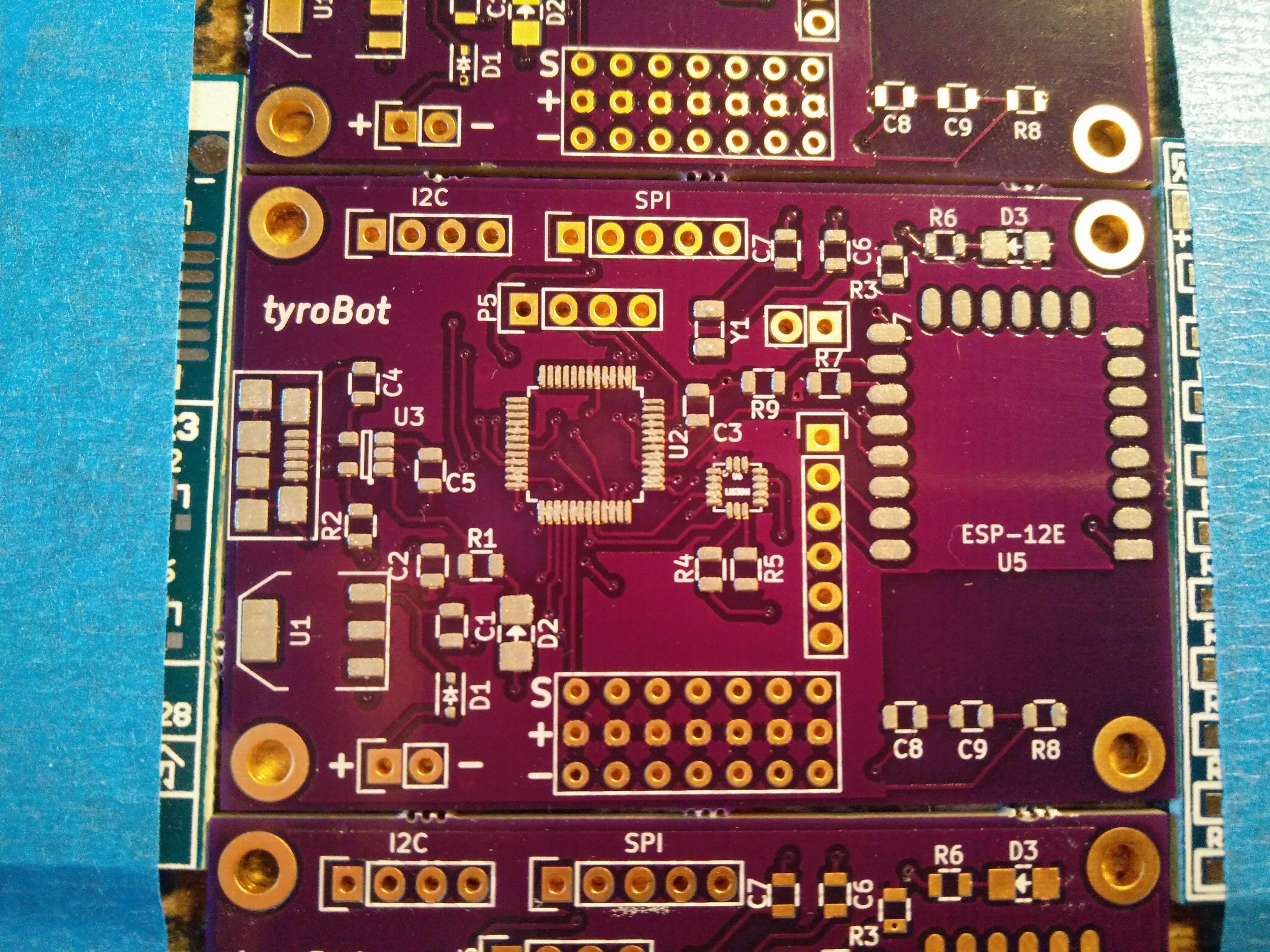
    4. Controller Board Assembly

      tyspa07/18/2016 at 23:04 0 comments

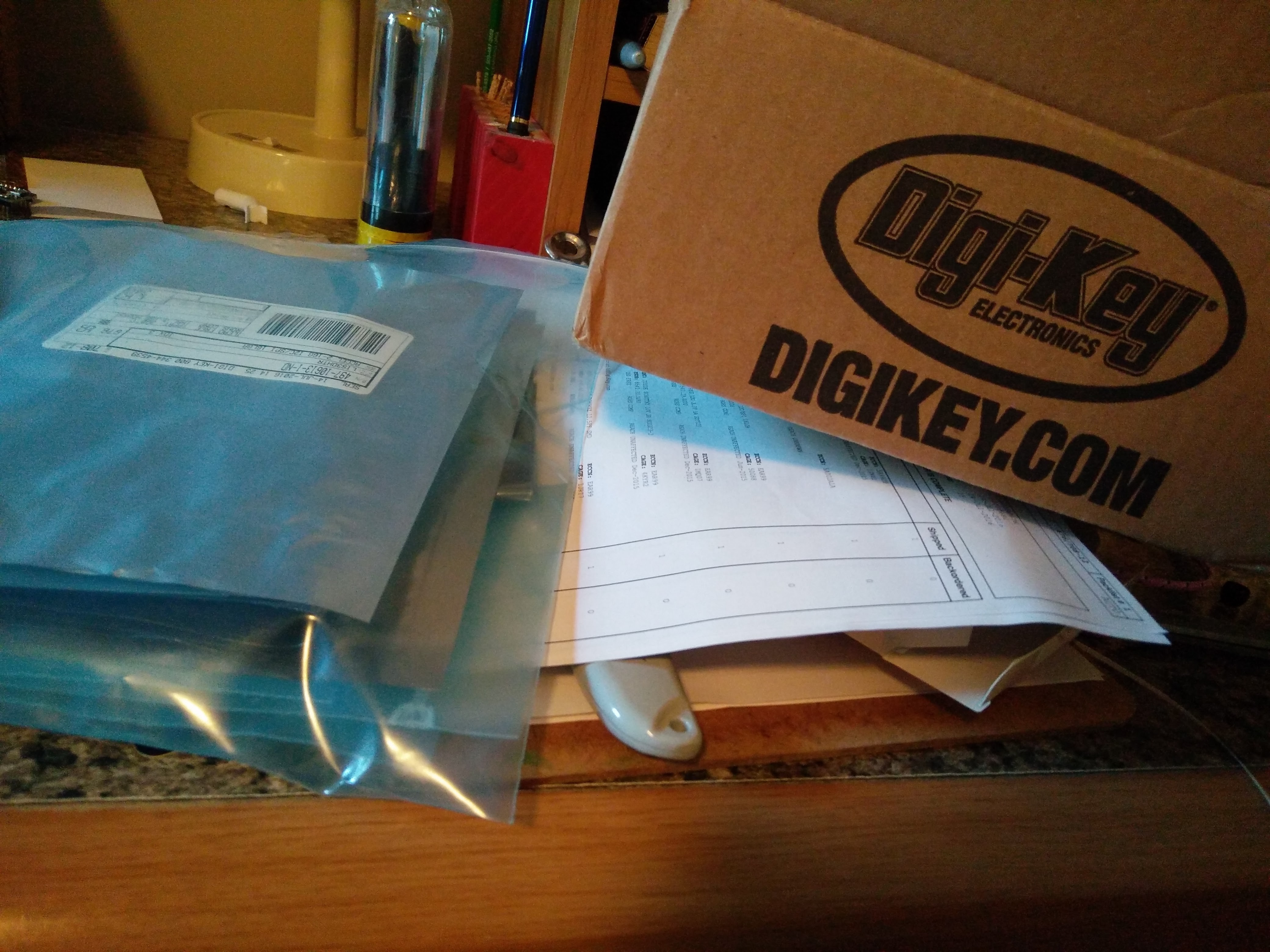
      Received the boards in the mail today from @oshpark, and I got the components from @Digi-Key Electronics on Saturday.

      Being the lazy type I purchased a stencil and reflowed the board in my toaster oven. Everything came out great, now to flash a bootloader and get coding.

      I don't have a J-Link or a Atmel ICE so I'm going to have to get a bootloader on there with a ST-Link v2. We will see how that goes...

    5. Head, arms, design files

      tyspa07/11/2016 at 19:06 0 comments

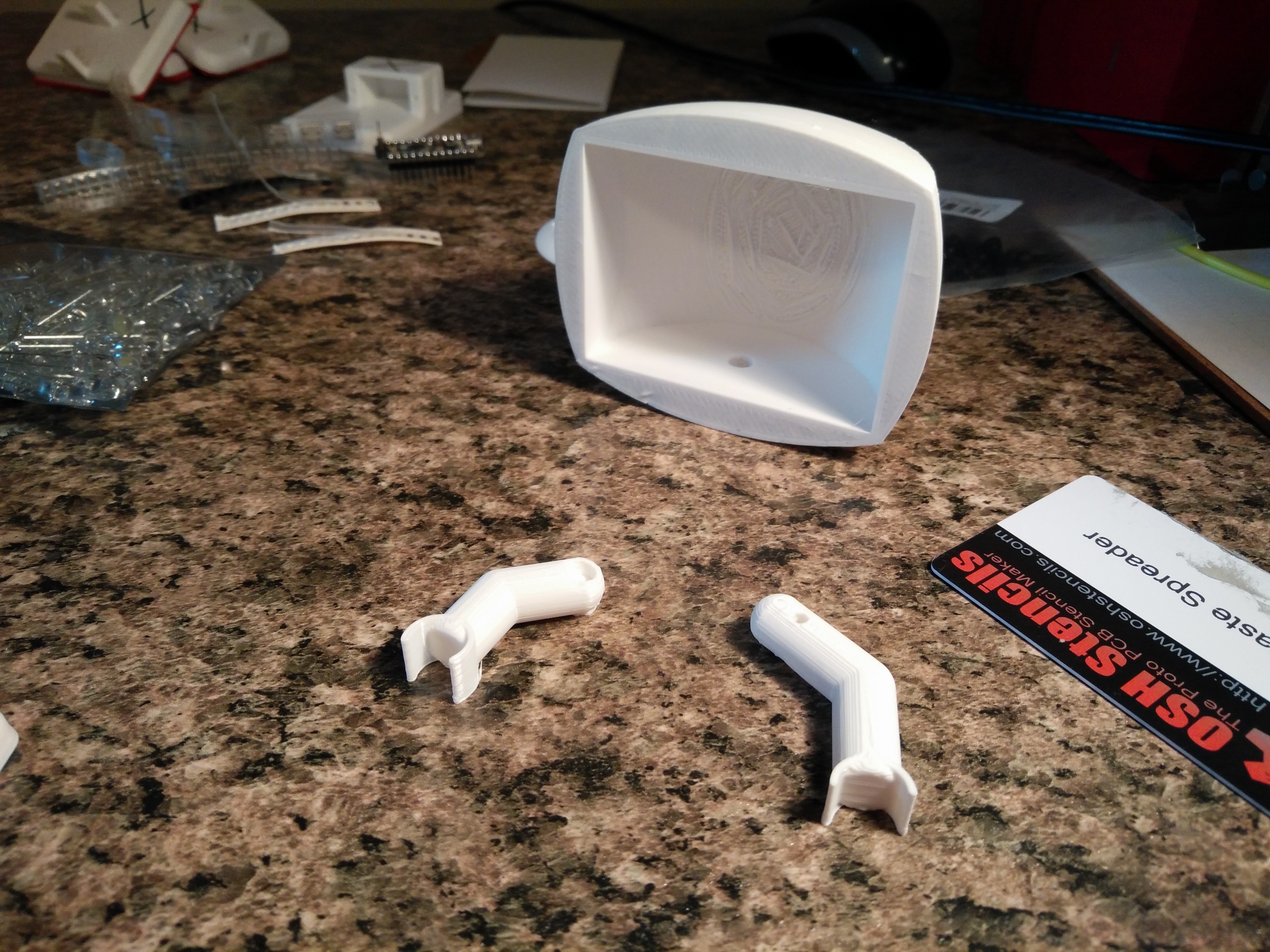
      After another week of work, I finished head and arm prototypes, ordered the controller board and parts, plus started some testing.

      I made the head kinda large, plenty of room for the controller board, battery, a servo, a 2.8in SPI TFT display with touchscreen, and maybe a Raspberry Pi Zero...

      I also did some work on the arms. They are kinda boring so I will very likely change them in the future. I also decided that orange would be a good color for the robot.

      Besides from that I ordered the controller board pcbs from OSH park and parts from Digikey. While I wait looks like i'll be doing some basic testing, display research, and trying to find SG90 servos in a color other than blue or transparent orange. Oh, and I published all the design files to github.

    View all 13 project logs

    Enjoy this project?

    Share

    Discussions

    Albert van Dalen wrote 02/11/2017 at 10:03 point

    I have made some libraries for the SAMD21, see my website, that may help you.

    SAMD21 Timer library for the SAM15x15 and Arduino Zero

    http://www.avdweb.nl/arduino/libraries/samd21-timer.html

    Fast PWM-DAC library for the SAM15x15 and Arduino Zero

    http://www.avdweb.nl/arduino/hardware-interfacing/samd21-pwm-dac.html

    Fast analogRead / 10-bit ADC for the Arduino Uno and Zero

    http://www.avdweb.nl/arduino/libraries/fast-10-bit-adc.html

      Are you sure? yes | no

    oshpark wrote 08/23/2016 at 17:47 point

    Awesome project!  We're looking forward to your further updates

      Are you sure? yes | no

    Camilo Parra Palacio wrote 06/21/2016 at 02:50 point

    Hi Tyler

    We have similar approach with Otto we also want a way of programming more simple, good idea with the accelerometer!

      Are you sure? yes | no

    deʃhipu wrote 06/17/2016 at 21:55 point

    Have you considered using ESP8266 with Micropython on it? That should be pretty easy to program and friendly to newcomers.

    Also, I'm not entirely sure how the accelerometer will help with accurate steps? Do you have a plan for that? I would love to hear more.

      Are you sure? yes | no

    tyspa wrote 06/17/2016 at 22:16 point

    I am currently deciding what the controller board will do/what features it should have. The esp8266 is definitely a viable option, haven't tried MicroPython yet but there is a Huzzah board waiting for it.

    For the accelerometer my plan (as of now) is to have it "confirm" the robots steps. The robot will walk based on prewritten code cycles, and the accelerometer will confirm the robot has shifted its weight. If the step fails, the accelerometer will know the bot is out of cycle and make sure the robot adjusts accordingly. Sounds good in theory, but we will see...

      Are you sure? yes | no

    Similar Projects

    Does this project spark your interest?

    Become a member to follow this project and never miss any updates