Over the past weeks I have been working with the board mentioned in the previous log. Unfortunately it didn't work 100% correctly (as expected with my talent).

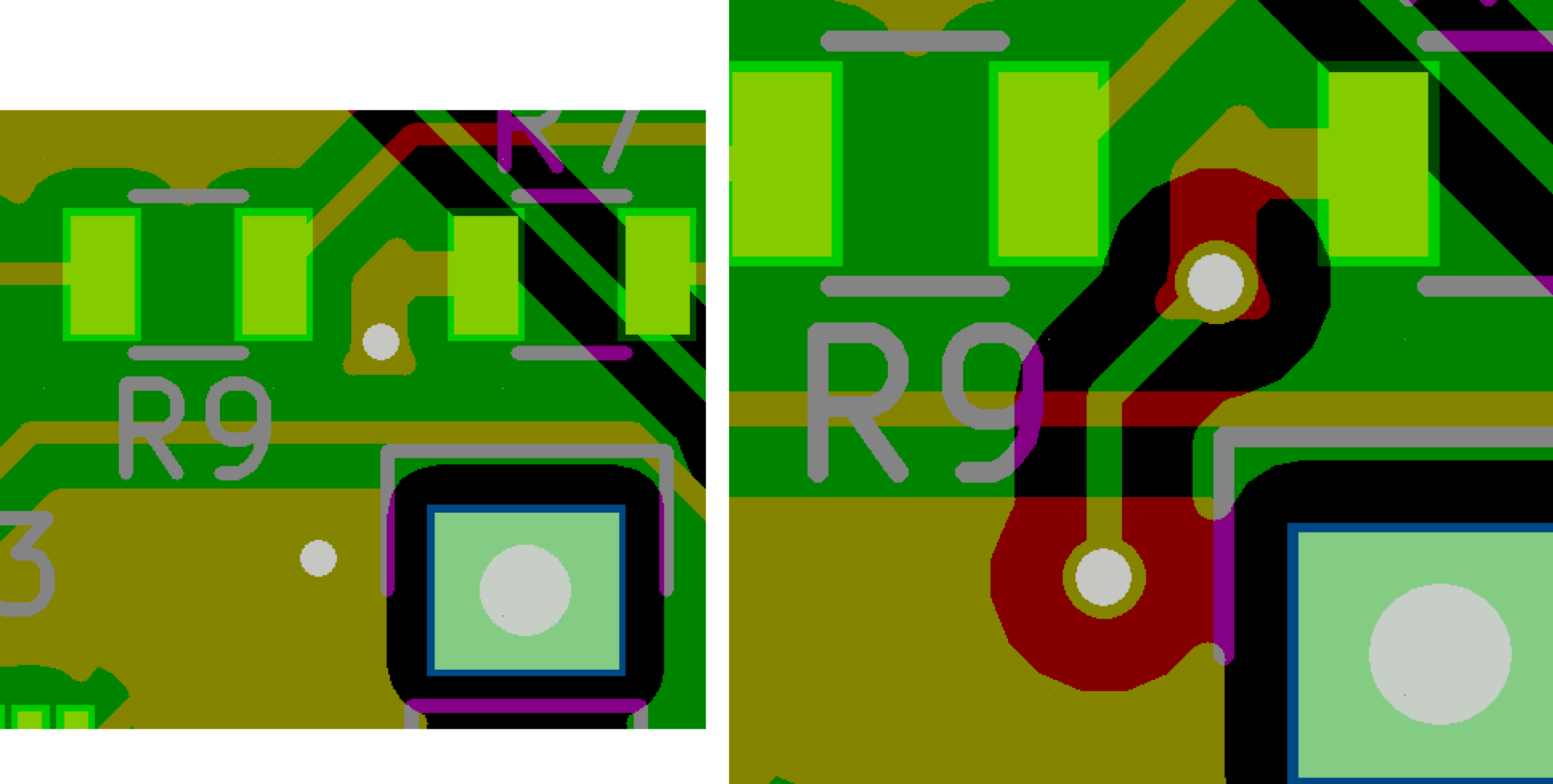
First there was the minor problem of the VCC rail directly shorted to ground. As you can see on the right the DRC didn't notice that the back copper fill hadn't been recently done. Thanks KiCad. Luckily I didn't ruin any components and the battery was connected to a diode. I was able to fix the board by destroying the trace with a razor blade. I also cut a trace from the ATSAMD21 to the esp8266, so the ATSAMD21 is unable to reset the esp8266 automatically. This is okay for testing purposes.
With that out of the way, I ran some basic tests.
- The power regulator worked great, but the voltage drop is too high. After a while the board will fail to power up even though the battery is still quite full. On the next board I will use a different regulator, and maybe drop the protection diode that saved the board earlier.
- The battery charging circuit worked as expected.
- I was unable to connect to the ATSAMD21. This I *believe* is due to the fact I left two ground and one VCC pin disconnected with the false assumption that they were connected internally. I tried soldering wire to the pins but they were right next to each other in the middle of the chip. I accidentally broke the ground pin while trying to solder. Very frustrating.
- I took a few days off to cool down from the above and played Pokemon Go.
- Since the ATSAMD21 is nonoperational, I was unable to test the accelerometer. It should be fine since all I did was copy the Adafruit breakout board schematic.
- The esp8266 booted up and worked perfectly, once I realized my FTDI breakout had the TX and RX swapped. I unintentionally swapped them twice, creating a double negative and connecting TX to TX and RX to RX.
TyroBot Board v0.2
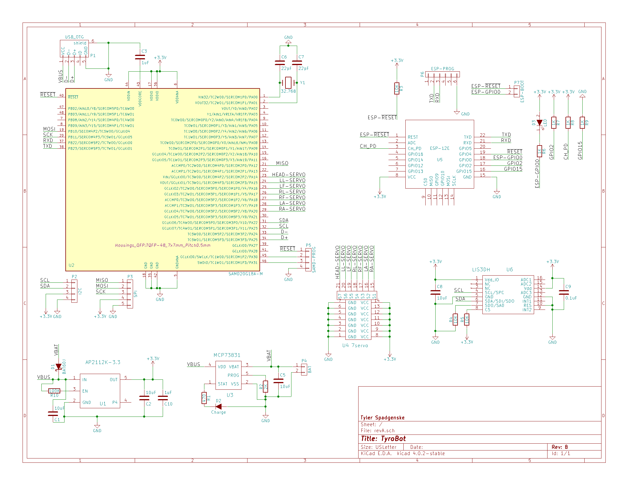
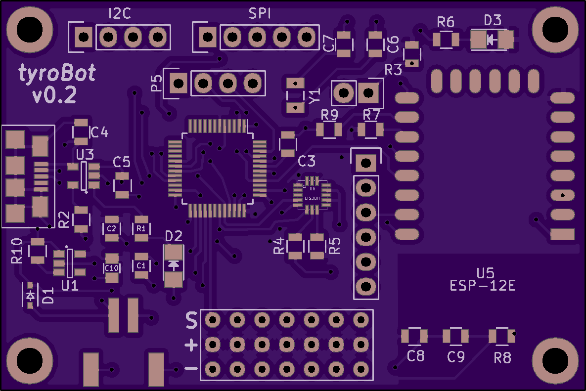
I corrected all the mistakes mentioned above, including switching the 3.3v regulator to AP2112K-3.3. Doesn't provide quite as much current output but should be fine. I also replaced the two pin battery connector with a JST connector. The scematic and board render are below, and the design files are on Github, so if you see any more stupid mistakes be sure to let me know.

 While I am waiting for the new boards, I hope to get the 3D models in working order running off a ATMEGA328 so I am not wasting time waiting for parts.
Discussions
Become a Hackaday.io Member
Create an account to leave a comment. Already have an account? Log In.
If you are using a lithium battery, perhaps it would be better to use a boost converter to something like 5V, and then regulate that down to 3.3V? This way it should support a wide range range of voltages. You can get small ready boost converter modules for lithium batteries easily.
Are you sure? yes | no
No component on the robot requires 5V, so I am going to try and avoid the use of a boost regulator. It may be necessary though to take full advantage of the batteries capacity, albeit at a current loss.
Are you sure? yes | no