-
Designing the Controller Board
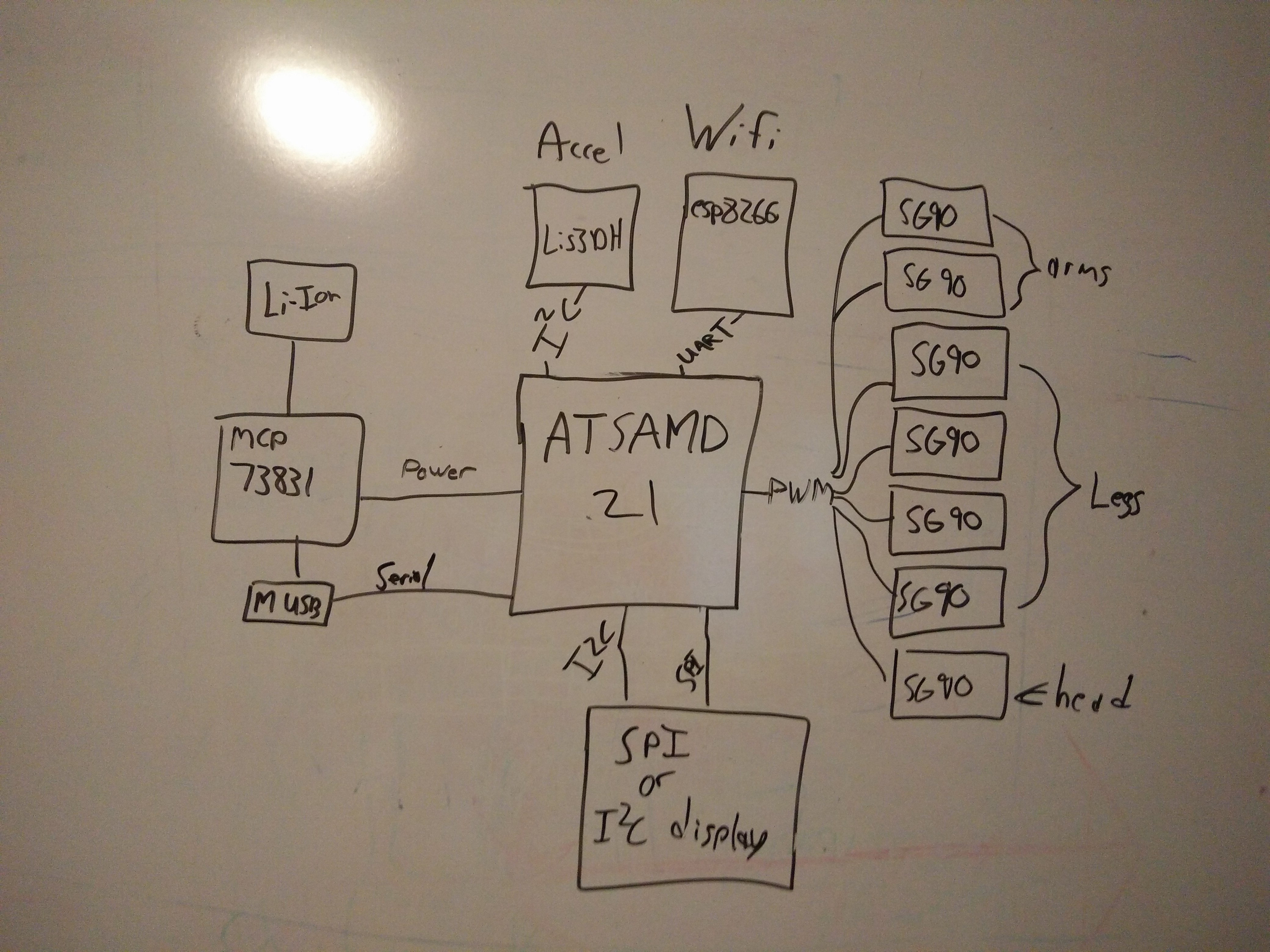
07/05/2016 at 21:29 • 0 commentsAfter some heavy research I chose the ATSAMD21 as the microcontroller for TyroBot. 48MHz, 38 io, 256KB of flash and 32KB of RAM should easily fulfill all the projects requirements. Below is the io that is going to be used.
- 7 pins for the servos (all pins on the ATSAMD21 can work as PWM)
- 1 analog in to monitor the battery
- I2C port to communicate with the LIS3DH accelerometer.
- I2C port for screen (may not be used if it is a SPI screen)
- SPI port for LCD (may not be used if it is a I2C screen, TBD)
- Serial port for communication with the esp8266
- Maybe a SPI port for an SD card slot
Below is a general flowchart of the electronics for #TyroBot
![]()
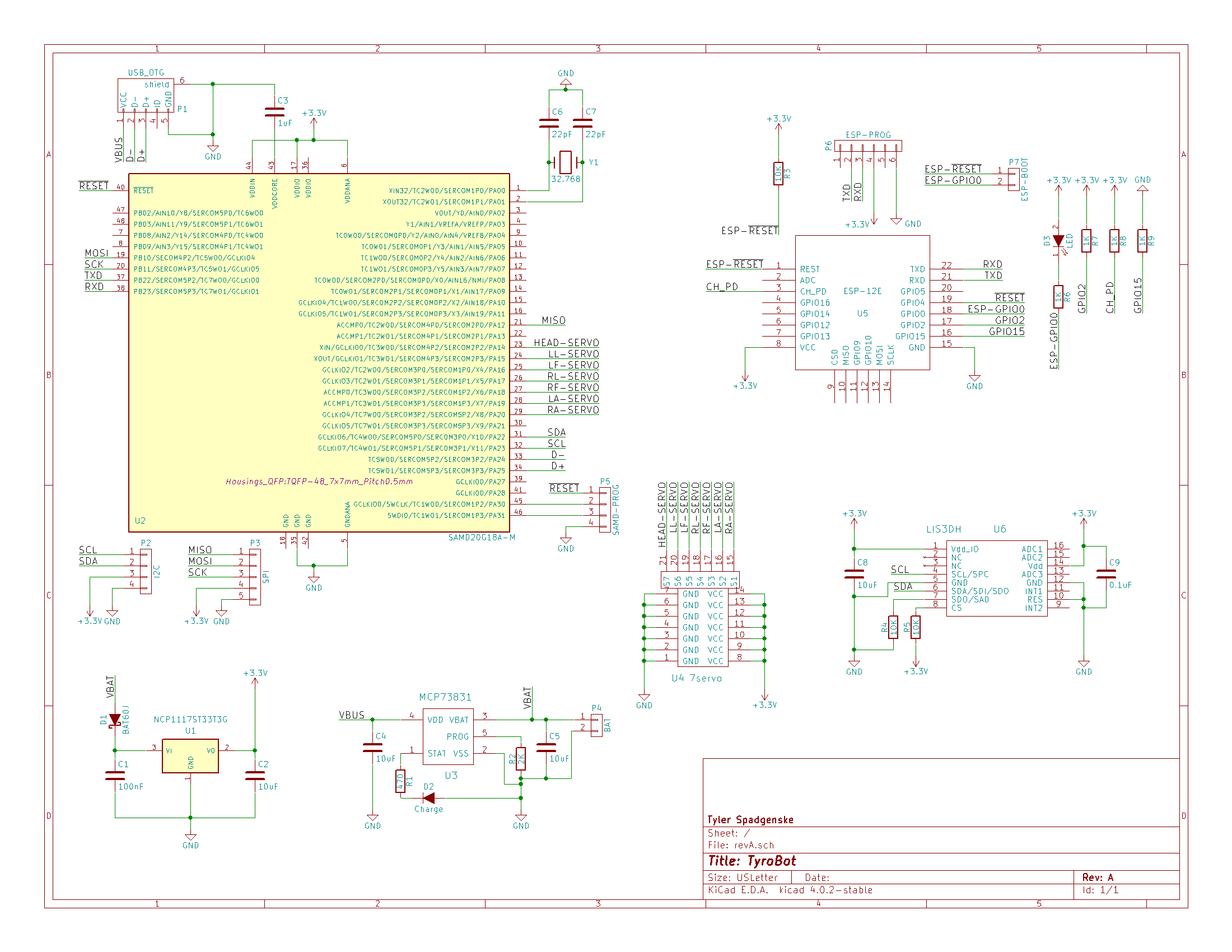
Next I drew up a schematic, slightly based off of the Adafruit Huzzah board, #mini SAM and #JACK by @Michele Perla For the charging circuit I just used the recommended application in the datasheet, which I used in my generic battery charging circuit.
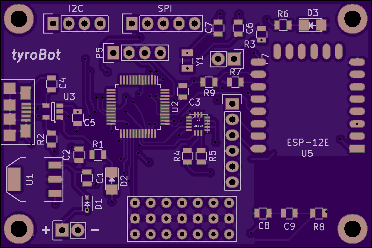
![]() I also did some layout and am currently checking for errors so I can purchase the parts from Digikey and send off the gerbers to oshpark. So if you see any flaws let me know. :)
I also did some layout and am currently checking for errors so I can purchase the parts from Digikey and send off the gerbers to oshpark. So if you see any flaws let me know. :)![]()
-
Rapid Prototyping
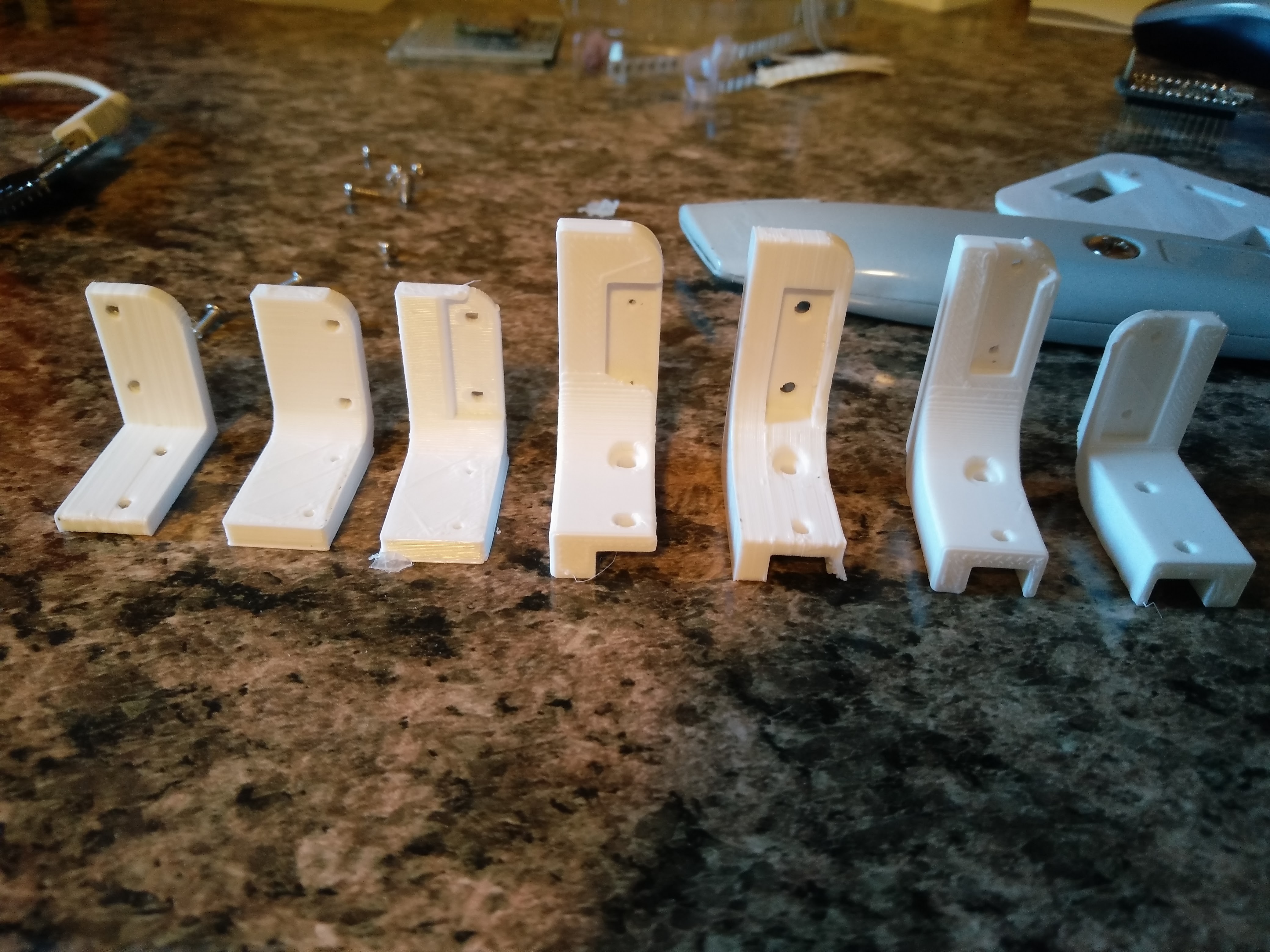
06/20/2016 at 17:57 • 3 commentsOver the past week I have been iterating the 3D printed mechanical parts for #TyroBot.
![]()
Starting from the ground up, I designed TyroBot's feet. After a few different designs I finished with a foot with the servo enclosed, and much more surface area than on BoB. The servo is screwed in with the two screws that come with the servo.
![]()
Next I spent a good deal of time perfecting the legs. I tried different sizes, hoping to get a more efficient walk cycle than that I experienced with Bob. I also wanted the servo horn to be as hidden as possible. What I ended up with is on the far left. Walking has improved but needs to be perfected.
![]()
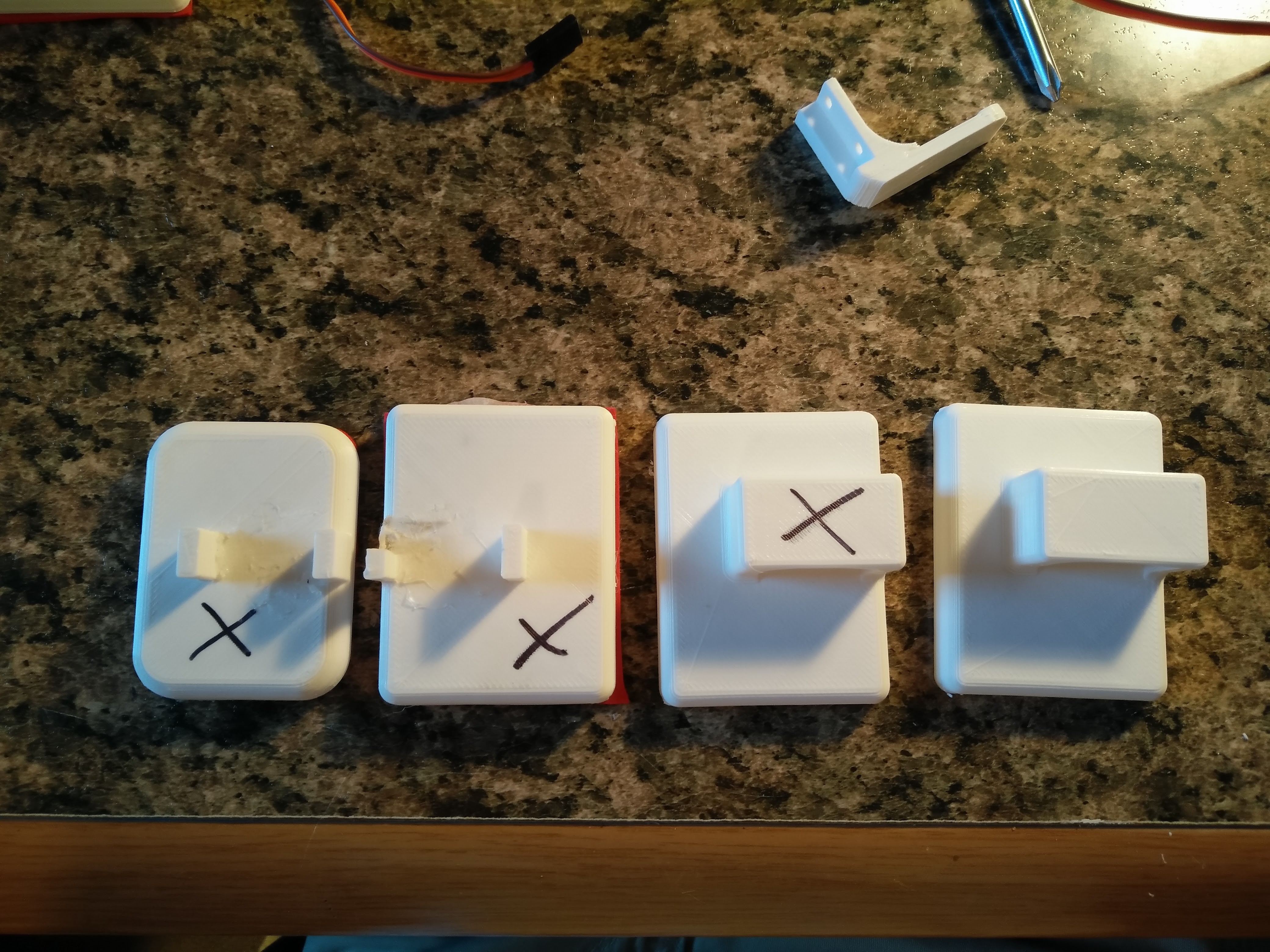
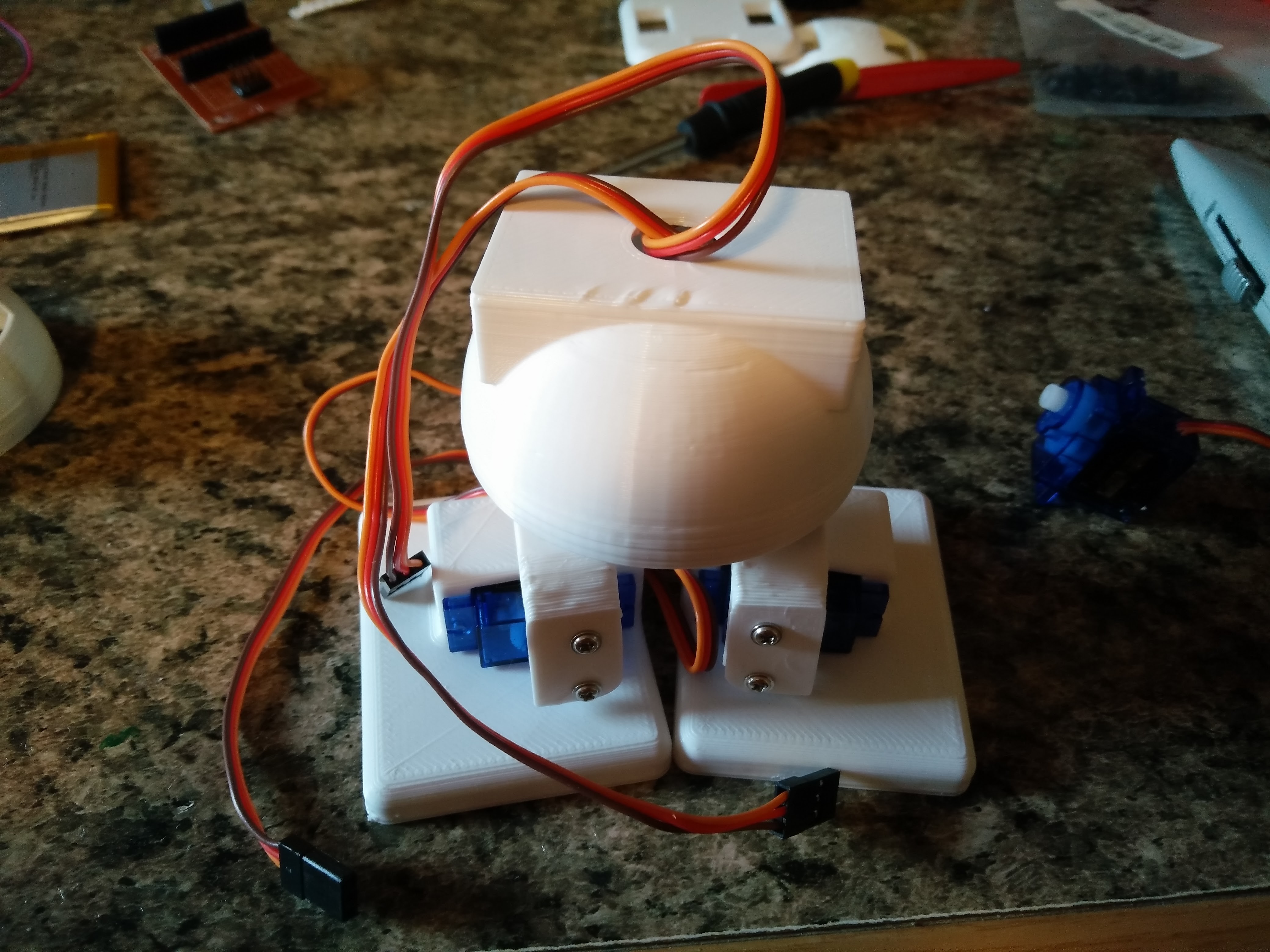
Finally we have TyroBot's body. I decided to go with a dome shape, just big enough to store the four servos for the arms and legs. There may also be room for a battery, but first I need to find a lipo that is more like a cube as most lithium ion batteries are too wide or long. Otherwise the battery will go in the head with the electronics. Hopefully weight isn't an issue...
![]()
Above we have the TyroBots current form, without a head or arms. The current plan is a have a OLED or TFT display in the head for user input, but I am still contemplating different designs. Hopefully over the next week or two I'll design the controller board and get those pcbs off to @oshpark
-
Standing on the Shoulders of Giants
06/17/2016 at 17:34 • 0 commentsBuilding a walking robot is not a trivial task, but luckily I do not have to start from scratch. For starters, the detailed project image sketch is based off of the project image for #Robotics Chat by @Radomir Dopieralski. I will also use the knowledge I gained from my 2014 Hackaday Prize Entry #ANDY: A Multi-Purpose "Humanoid" Robot
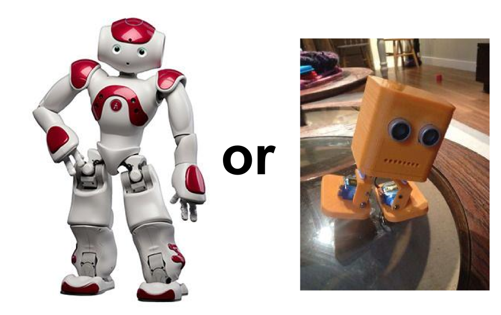
After browsing the internet for quite some time, I came to the conclusion that either you had to pay thousands of dollars to get a advanced humanoid robot (almost always using proprietary technology) or hack together your own. There are a few options in between, but still two expensive with too little support for my liking.
![]()
Of course I had to start out by building my own BOB the biped (the image on the left). I 3D printed out the files in white PLA on my Lulzbot Mini and assembled him with machine screws and SG90 servos purchased off of ebay. since pretty much all the code for BOB is based off Arduino, I used a Adafruit Pro Trinket 5V Hackaday Edition as the MCU.
![]()
I flashed the first BOB arduino sketch I could find, and lets just say things didn't go smoothly. First, the servos tried moving to a position that didn't exist, and then the robot made jerky movements before tipping over. I played with the code for an hour or two before finally giving up and looking for more code to try. Next I some code that used some heavy duty mathematics to figure out how BOB should position his steps. This code partially worked, but the robot would still tip over every 2 or three steps, or stall the servos. When the robot did take the steps successfully, it was not in a straight line at all. After modifying the foot size writing my own code from scratch, I finally got decent results.
After some more research I discovered the Zowi project from BQ Labs. Their code is heavily optimized for their Arduino derivative with Futaba 3003 servos. This is proof that you can get great results with just a 4 DOF biped, so that is what I am going to start out with on TyroBot.Although Zowi has the walking part down, the project mainly relies on the app limiting its practical use.
Conclusion
In conclusion, TyroBot will work just fine with just four degrees of freedom. It will just require a sturdy structure (which BOB lacks) a good codebase (like Zowi) and a Accelerometer to help TyroBot make accurate steps. I included a list of project goals in the project description.
TyroBot
Easy to build and program walking robot. Powerful 32bit microcontroller, 7 servos, touchscreen display, and 3D printed parts
