 Michel Kuenemann
I have built a mockup to test the algos of the BMS:
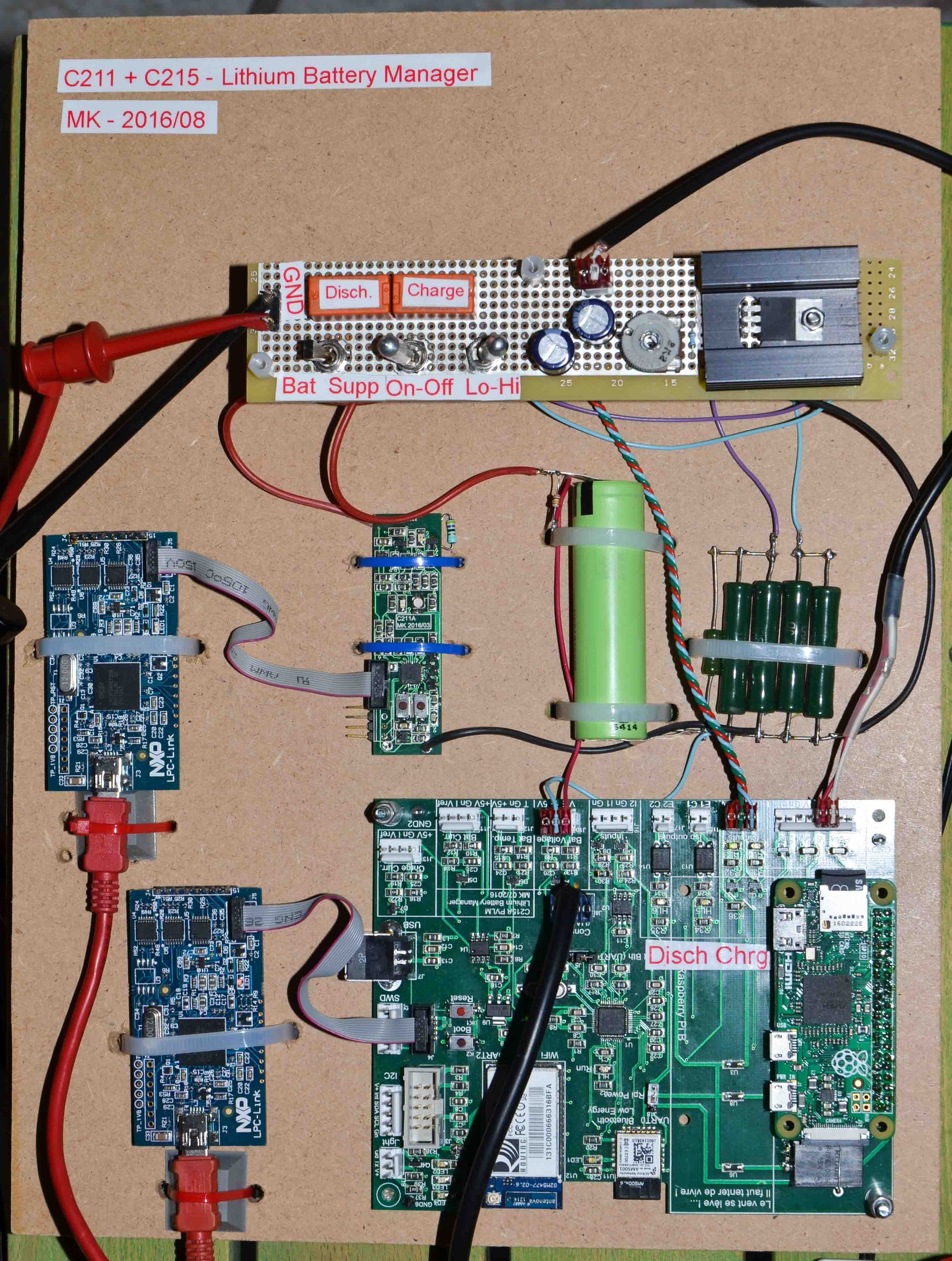
This mockup comprises one single PANASONIC 18650PF cell (in light green).
The cell is connected to the Module management board (on the left, secured with blue cable ties).
On the right of the cell 5 dark green power resistors serve to dissipate the energy of the battery .
Below the cell the Main BMS board manages the charge / discharge cycles.
The cell is charged thanks to a basic linear supply (LM317 + dissipator).
Discussions
Become a Hackaday.io Member
Create an account to leave a comment. Already have an account? Log In.