-
Website
08/25/2014 at 22:11 • 0 commentsJust created a website for the project :)
-
Parts
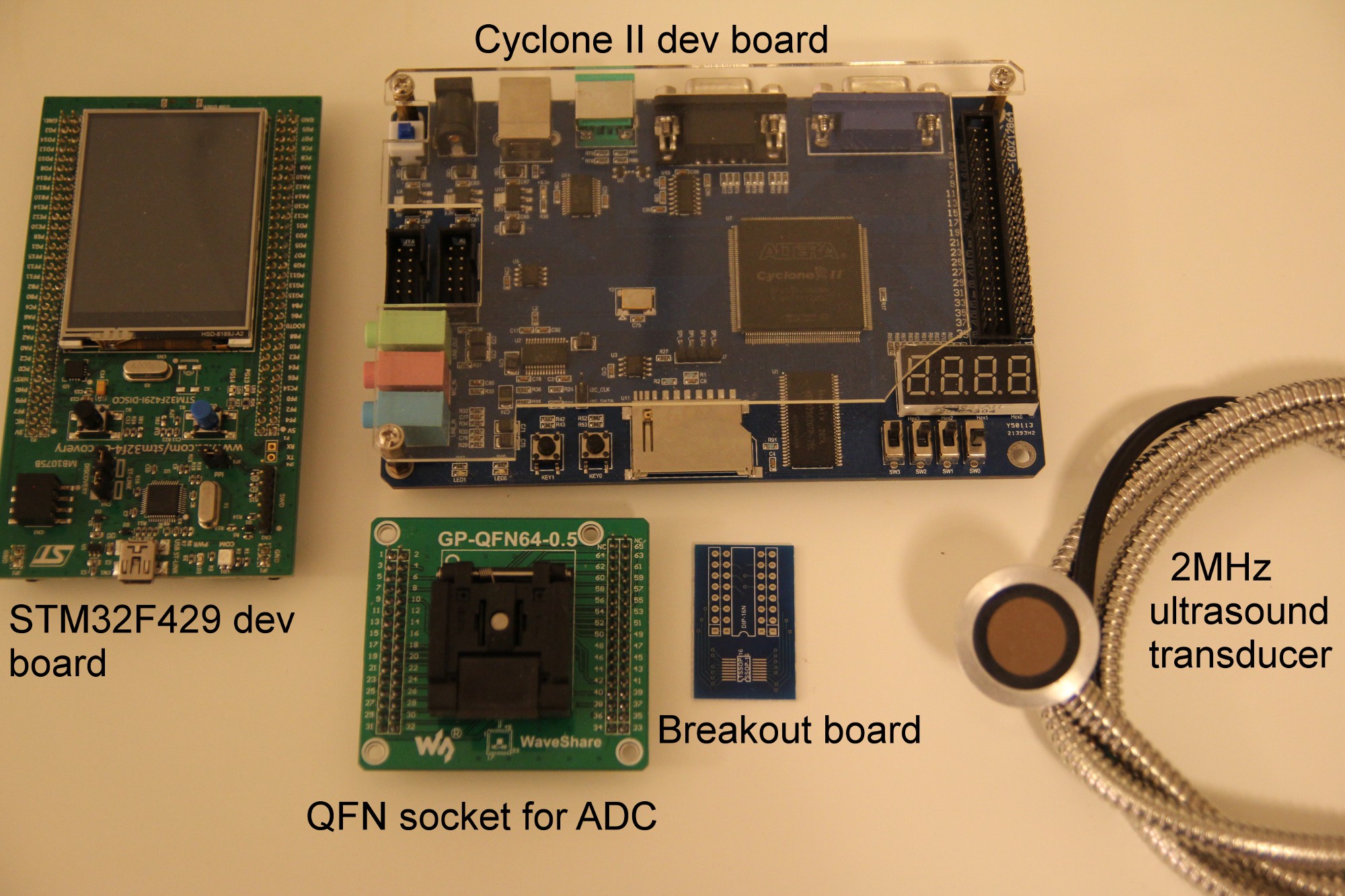
08/19/2014 at 21:19 • 0 commentsBelow is an annotated array of parts that I currently have:
![]()
One of the main components I need to obtain now includes an amplifier chip. I already have the ADC, DAC and pH chips.
Next steps:
* Assemble prototype using the above parts!
* Test ultrasound pulses are being correctly generated using oscilloscope
* Program FPGA using VHDL in order to monitor returned pulses
* Build chamber (out of a drainpipe!)
* Complete schematic design
* Get PCB fabricated!
* Assemble PCB
-
Github
08/17/2014 at 19:53 • 0 commentsI've just been working on adding datasheets for each of the main components which will be used, to a github repository for zymeter.
Click here to find it!
Additionally I've also added the KiCad components and the schematic. So you can quickly see as the schematic progresses.
-
Schematic design with KiCad
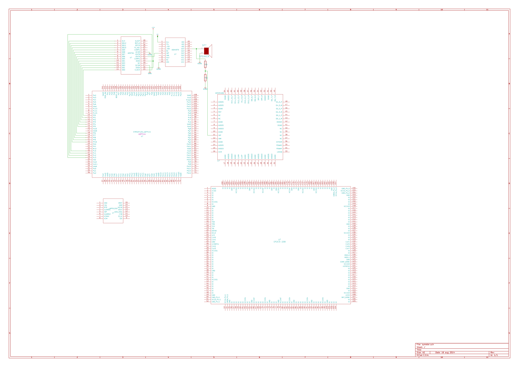
08/16/2014 at 13:46 • 2 commentsI haven't properly tried to use KiCad before. I'm mainly used to using Eagle, but it seems like knowing KiCad would be a very useful skill to have, especially as it's Open Source.
The schematic is currently in very early stages, I've added the main components though I believe.
A number of these I had to design myself. I found quite a useful webpage though, which makes designing the part a lot quicker: kicad quicklib
![]()
I will also work on adding these files to my Github repository.
I'm currently also looking more into how to use the ultrasound transducer to both emit and receive pulses. I'm not sure how the voltage levels of the pulses emitted compare to those recieved, at the moment - if anyone has got any info on this or rough figures, I would be very interested to know!
-
Chamber
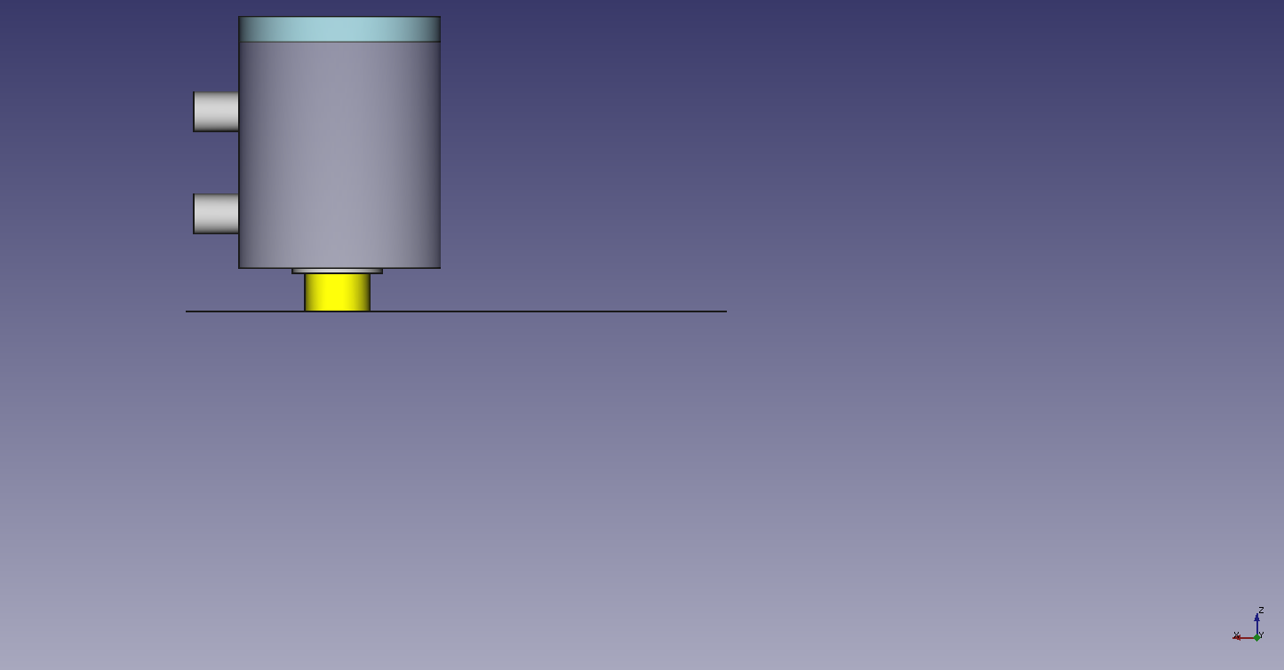
06/15/2014 at 15:40 • 0 commentsThe chamber will have two pipe connectors, in order to pump liquid through it.
At the top of the chamber will be a piece of glass, which will be used in order to create a well defined reflection of the ultrasound pulses.
![]()
In order to pump liquid through the chamber, I will likely make use of a peristaltic pump, as we don't need a high flow rate and also they help keep things sanitary.
![]()
-
Transducer CAD model
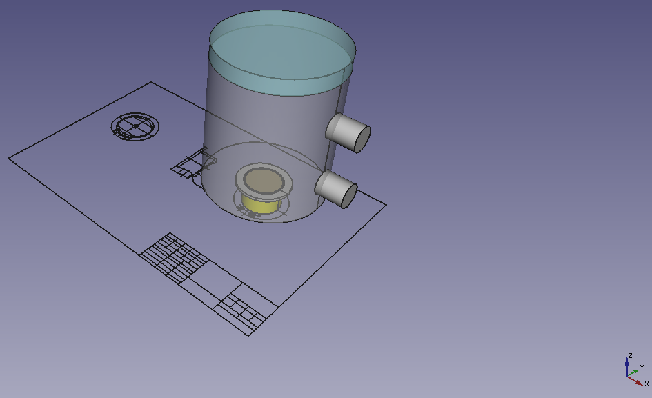
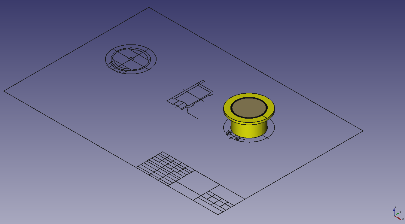
06/15/2014 at 13:26 • 0 commentsI'm currently working on creating a 3D model of the transducer and chamber in FreeCAD, based on the transducer's 2D CAD drawing, I obtained from the manufacturer.
The transducer has a 2mm thick flange, which I'm thinking of either clamping to the chamber, or making use of some form of adhesive. Ideally clamping would be best, for long term usage I think.
![]()
-
The Original Idea
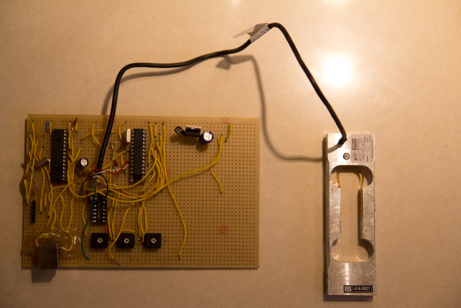
06/06/2014 at 16:43 • 0 commentsI just thought I'd show what the original approach I took looked like, when I was using the load cell. It makes use of a PIC32 microcontroller along with a differential ADC. The output from the ADC was then fed to the PIC. The PIC then output readings from the loadcell via USB.
![]()
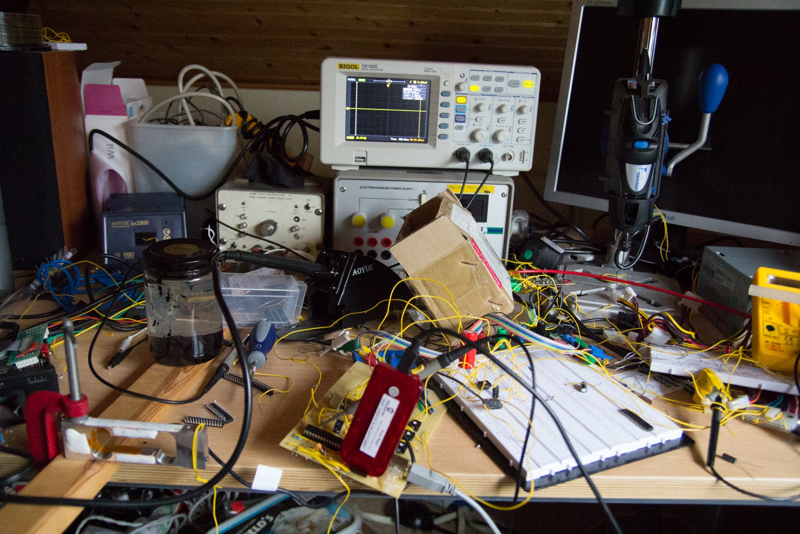
You can see the test phase below, with me programming the PIC chip.
![]()
-
Fancy hardware :)
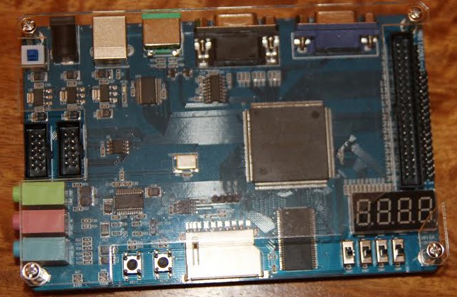
06/05/2014 at 19:25 • 0 commentsBelow is the FPGA board I will be building the prototype with (It uses a Cyclone II FPGA). You can see it has a number of GPIO pins, which I can use for the ADC.
![]()
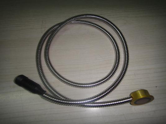
Below is the 2MHz ultrasound transducer in all its glory
![]()
-
Acquiring components
05/25/2014 at 23:14 • 0 commentsI'm currently in the process of acquiring the components I need for the project. I've added them to the list of components that I'll be using.
I'm planning on using an FPGA to process the signal from an ADC. The ADC will recieve the pulses from the ultrasound transducer. From the pulses I aim to measure both the speed of sound in the beer along with the amplitude of the pulses. By combining these two variables it should be possible to measure the specific gravity according to scientific literature.
Zymeter
A device to monitor the progress of fermentation (pH, specific gravity, alcohol, temperature)
 anfractuosity