-
Round 2, Fight!
06/28/2016 at 04:25 • 0 comments(October 2015)
With new PCBs in hand, I assembled two to get going on testing. I still need to get the IR working, and the value of the phototransistor pullups still needs to be determined. I also ordered stencils for this version of the PCB from OSHstencils, and used a mini hotplate to assemble the backside of the boards. The front side was stenciled, but I did the reflow by hand with an iron.
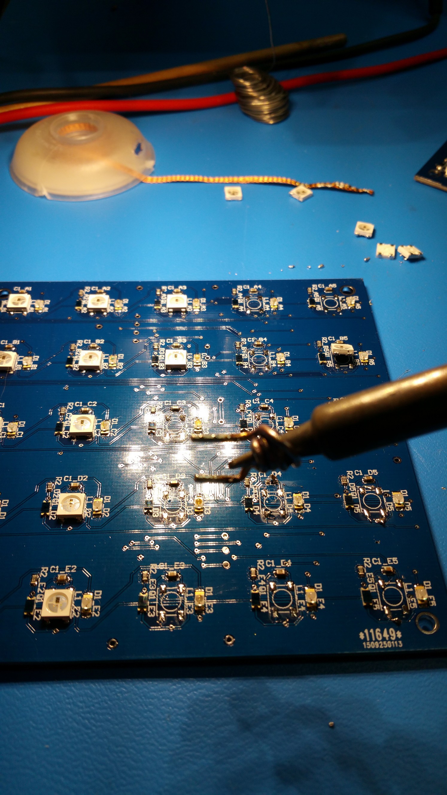
Too bad the silkscreen was wrong by 180 degrees on the Layout. Or at least I thought it was. In the end it wasn't. Unfortunately, I had assembled two boards before discovering this. I remembered a good hack from hackaday about using heavy gauge solid core wire to upgrade a soldering iron to a desoldering iron that could be used to heat two joints at once. I adapted this for the 4 joints on the WS2812.
![]()
This worked pretty well, and i was able to save many LEDs and get them turned the right way. Luckily, the WS2812 has reverse voltage protection, and I hadn't been using the 20A power supply to test them! The thing that clued me in to them being backwards was that my power supply was going into short circuit protection when I powered the board. My vintage adjustable bench supply can only put out an amp, so it tends to be picky about overcurrent.
Even after fixed the LEDs, it was still going into overcurrent protection, so something else was up. I then discovered how DirtyPCBs can be so cheap. They do a reasonably good job, but sometimes there is an etch error, and they fix them by hand if the E-test catches them.
![]()
Almost every single board had some kind of small repair like this, inked over in blue sharpie. There were a few minor power shorts that they did not catch and fix. I learned a trick as an intern at iRobot for fixing a power plane short on a populated PCB. if it's a small enough short, simply hook up to a nice big supply at the rated voltage. I had purchased a 5V 20A supply for this project (back when it was going to be 729 LED cells instead of 225). This power supply did the job in short order. They mostly turned out to be a ground trace caught on the edge of the Vcc plane. Freshly un-shorted and cleaned up, ready to repair
![]()
![]()
There were also a few cases where the solder mask relief around a pad went a hair to far and exposed the copper of a power plane. Since the footprints of the IR bits were a tad too small, I ended up with a few shorts from this too. With all the PCB errors fixed, I can finally get on to the code! -
Aziz, Light!
06/28/2016 at 04:24 • 0 comments(October 2015)
Over 5 weeks from the original shipping notification, I finally have gotten the WS2812s. Turns out the shipper shipped them China Post, when I paid for the upgrade to China DHL. It also turns out that AliExpress has a clause for unilateral changes to shipping method. Over 2 weeks of dispute resolution process later, and AliExpress forced the seller to refund the whole shipping cost. As a result, I got 300 LEDs for $13, shipped. I wouldn't recommend seeking to replicate these results, but being able to quote the rules and having screenshots to prove everything was quite handy. I'm only 2 months behind schedule now!
Now that I have some LEDs, time to get them attached to the waiting board. I had tested out the back side, and made sure all the power supplies were working (after some troubleshooting). I got the first board together and tried to test it. The color LEDs were fine, but I simply could not get the voltage for the IR LEDs and the Shift registers (separately adjustable) to reliably trigger when the IR sensors were touched. I was counting on this particular flavor of shift register to have the threshold voltages on thee inputs adjust with Vcc. They do, but the analog circuitry of the phototransistor just couldn't provide enough swing to work nicely.
I decided in the end that I would use an opamp/comparator on each phototransistor, with a global 10k pot to set the threshold on all 25 sensors (per board). I looked at various other methods and part costs, and couldn't find much cheaper than a LM339. I was not looking forward to bodging on 7 TSSOP-14 ICs dead bug style, so a new PCB rev would be needed. I hadn't used up many parts on the first boards yet, so I was able to get away with only ordering the LM339s and some more passives to keep my options open on the phototransistor pullups.
The second rev boards had the added LM339s, and removed the shift register variable power supply. I kept the adjustment for the IR power supply for brightness control, and a 10K pot was added for the IR threshold level. DirtyPCBs came through again with fast turnaround and DHL shipping to get me going before the end of October.
-
Mail call
06/24/2016 at 23:15 • 0 comments(September 2015)
Once I had the boards on order from Dirty PCB, I also put together the digikey and AliExpress orders for the components. AliExpress was by far the cheapest way to get the LEDs. I spent a fair bit of time looking at different vendors and calcuating total price per LED including shipping. I planned to use DHL China for speed, so that helped narrow the vendors. AliExpress vendors commonly do the "EBay Trick" where the cost is cheap and the shipping is expensive to show better in the listings. If you were planning to pay a lot for shipping anyway, then these can actually be pretty good deals. I ordered 300 LEDs froma vendor that claimed $4/100, and with express shipping, it came out to just above the normal price for the LEDs.
Things started arriving later in the month. PCBs:
![]()
![]()
Digikey parts added to my project box
![]()
I assebled the back side of a single board to see how thing looked
![]()
And then we wait for the LEDs...
-
PCB design
06/24/2016 at 23:01 • 0 comments(August 2015)
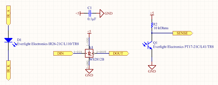
I did the PCB design as a way to evaluate CircuitMaker. I already use Altium Designer at work (occasionally), and I got into the Circuitmaker Beta and wanted to try it out. The basic LED/sensor cell is fairly straightforward. A WS2812B, a Cap for decoupling, and a LED/Phototransistor pair with supporting resistors.
![]()
The IR LEDs will be chained together to reduce the number of resistors and the power loss.
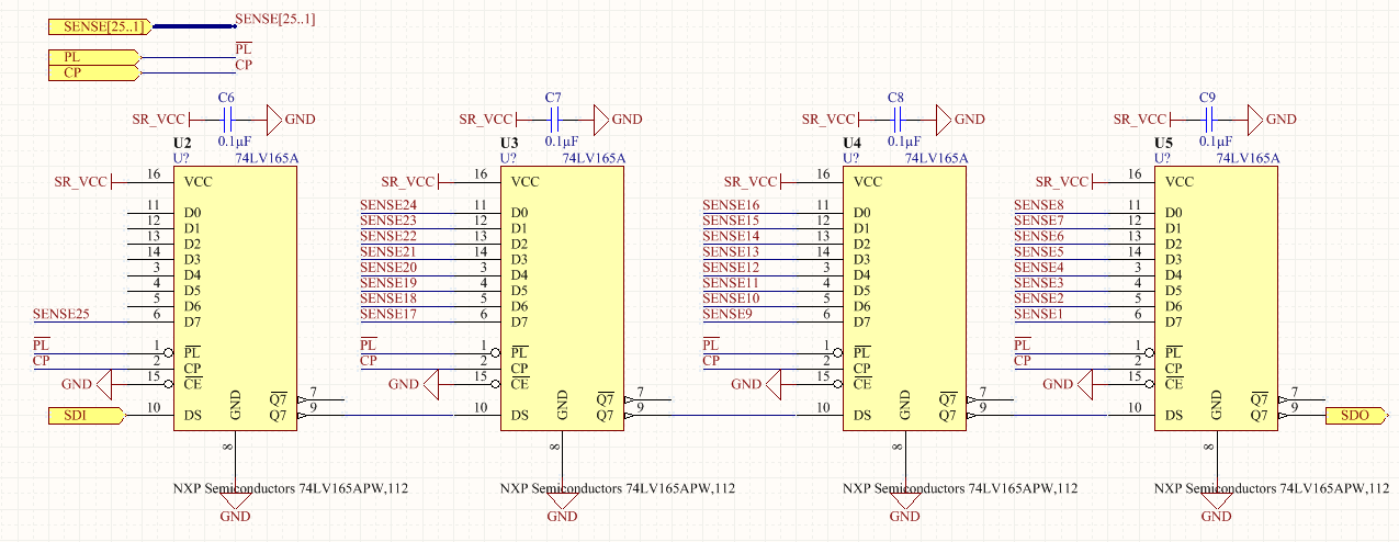
The Sense lines run to a bank of shift registers:
![]()
Unfortunately, with 25 sense lines, I needed 32 bits of shift register. Using shorter registers (but more of them) would have been more expensive.
Lastly, the power supplies to adjust both the IR LED power, and the VCC (and therefore threshold voltages) of the shift registers.
![]()
It turns out I got the power supply resister values wrong because I used the wrong formula from the datasheet, but that's easily fixed later.
Once I had the basic layout of the cells on the top and the shift registers on the back, I started the routing, which I also timelapsed. Here's the last 4 hours of routing in under 2 minutes:
-
Prototype
06/24/2016 at 03:39 • 0 comments(July/August 2015)
Erica wants to learn processing, so she asked me to create a programmable widget that she can talk to and control. She wanted a light display with the ability to interact with it via touch/proximity sensing.
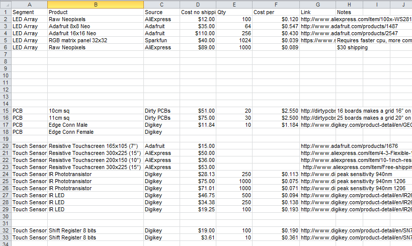
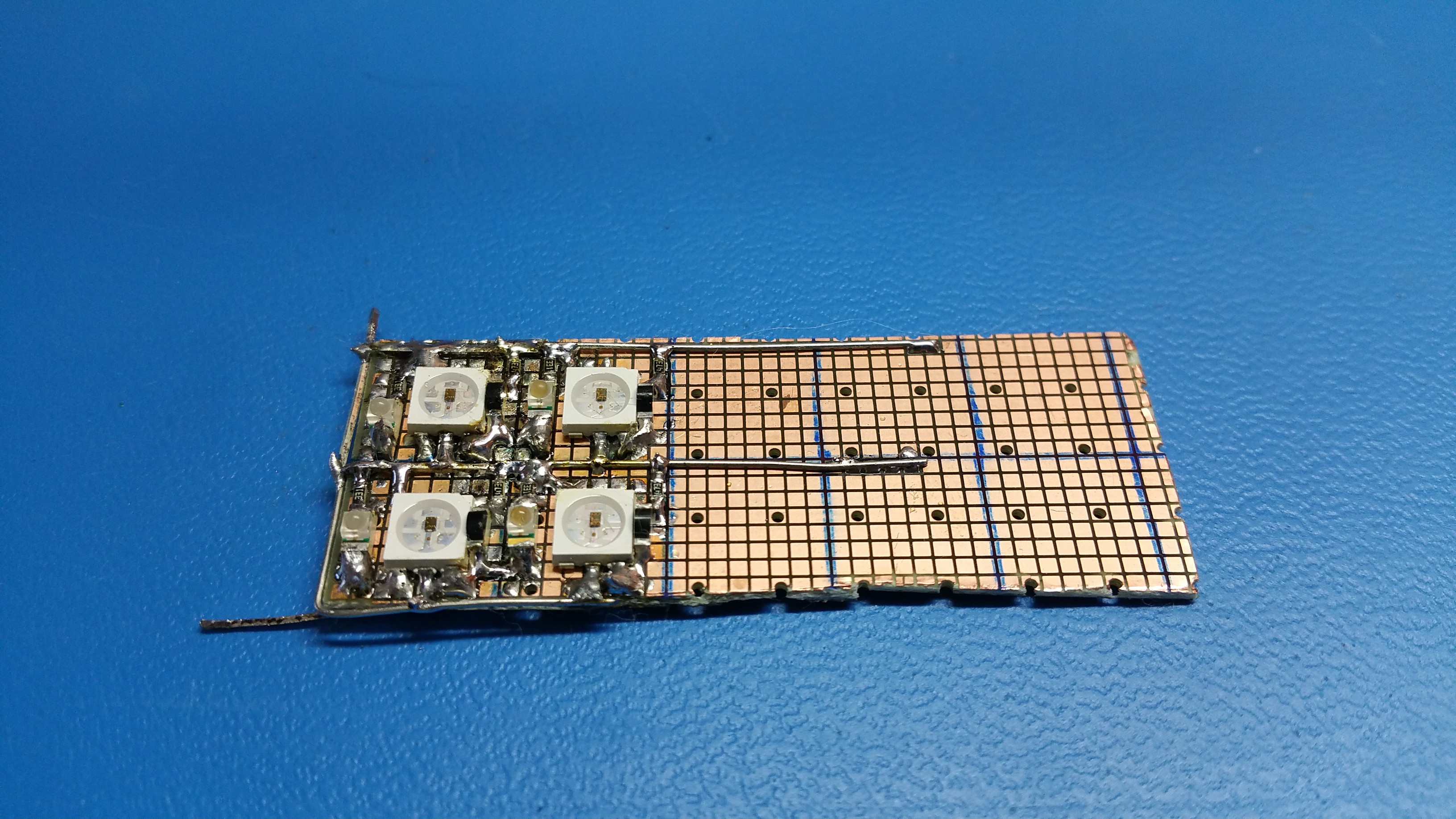
To get her started, I hooked a NeoPixel strip from adafruit to a Arduino Micro, and developed a serial interface to it in processing that she could use. In the meantime, I started looking into options for what to build. First was a process of looking at all the plausible display and sensing options:
We settled on raw WS2812B with the IR transmitters and receivers on each side. The first prototype with sensors had a 10mm cell pitch, and was made on some SMD protoboard with parts on hand. The Color LEDs were the original WS2811 (6 pin) variety, and the IR LEDs and phototransistors were leftover from a project at work.
![]()
I realized the IR LED and phototransistors would interfere with each other in this configuration, so I alternated them when I expanded the prototype.
![]()
This density was a bit much, but seemed possible. I was able to hook this up to an Arduino and show that the basic concept worked. We then worked out a cost matrix for different options and densities, to estimate total project cost (of the major components) based on this basic design, selecting Option 5 in the end.
The next post will go through the PCB design and BOM.
Interactive Color LED grid with IR touch sensing
My wife wanted some hardware to program with processing. I wanted to design some PCBs
 engunneer