I have moved from breadboard to perfboard. The schematic had a couple of components for the rain gauge and one additional ADC to compensate for the fact that the ESP8266 only has one ADC on board. These three components added a reasonable cost to the board and it was hinted that another microcontroller maybe added to the system to replace these components.
Enter the STM8S.
Hardware Modifications
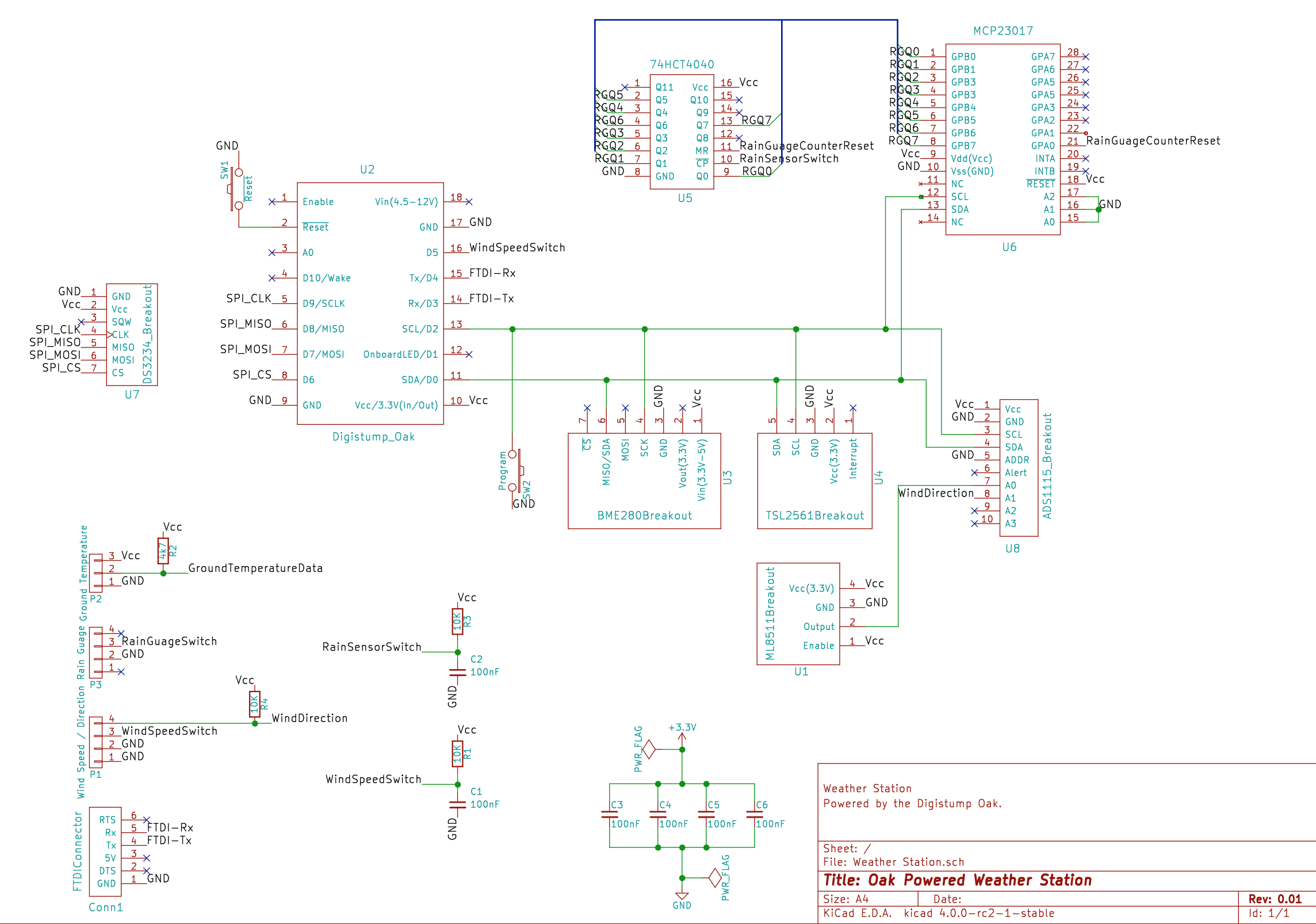
The previous version of the schematic looked as follows:

Three components are being targeted for replacement:
- 74HC4040 - counter
- MCP23017 - I2C output expander
- ADS1115 - 4 channel ADC
These components come to several pounds (dollars) worth of components. It may be possible to replace these with the STM8S and a little software.
ESP8266 Low Power Mode
A long term goal of the project is to reduce the power consumed by the system in order to allow the system to work from a battery / solar energy source. In order to work towards this goal the system should be looking to shut off as much of the system as possible when they are not needed.
Initial thoughts are that the system should collect data every 5 minutes. This means that most of the system is only required for a few seconds (say 10 seconds) every five minutes.
One exception is the rain gauge. This needs to be counting all day, every day as a sample taken at a point in time is not representative of the rain fall for a full day.
Another exception is the Real Time Clock (RTC). This needs to be running all of the time for two reasons, firstly it keeps track of the current date and time. Secondly, the system can generate an interrupt to wake the system on a regular basis.
Adding Another Microcontroller
Regular readers will no doubt be aware that I have been a regular user of the STM8S. This microcontroller is available in packages starting at around £0.72 (about $1). Even the smallest packages have several ADCs and multiple digital input / outputs potentially reducing the system costs.
One other area that a microcontroller can help is with the chosen RTC, the DS3234. This RTC can generate an interrupt when an alarm time is reached. The interrupt generated is a simple high to low transition. The ESP8266 however requires a pulse. The STM8S can help by providing this conversion, detecting the falling edge and generating a pulse for the ESP8266.
Sounds perfect.
Updated Schematic
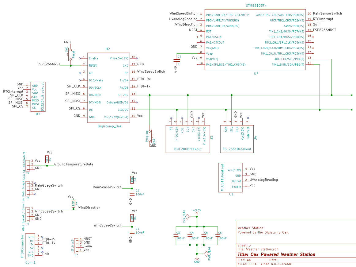
Several previous posts have shown that it is possible to perform analog conversions and also capture interrupts. This makes it possible for the STM8S to gather several sensor readings for the Oak and replace some components, namely:
- ADS1115 4 channel ADC - The STM8S has several ADC channels and the system only requires 2 so far
- MCP23017 I2C Port Expander - Several digital channels remain available even after using some pins for the ADC
- 74HC4040 Counter - This functionality can be provided through software and a digital channel
Another attractive feature of this microcontroller is the ability to act as an I2C slave device. This will work well with the other digital sensors as they all use the I2C protocol, one protocol to rule them all.
A few changes to the schematic results in the following:

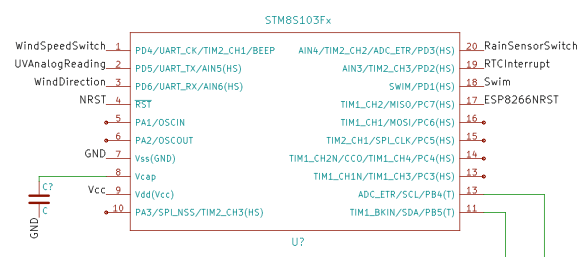
Focusing in on the STM8S:
 The STM8S should be able to take over the reading values from the following sensors:
- Ultraviolet light
- Wind direction
- Wind speed
- Rain Gauge
All that is needed now is some software. Time to break out the compilers.
Conclusion
Adding a new microcontroller adds some complexity to the software development whilst reducing the cost of the final solution.
Next steps:
- Putting the Oak to sleep and using the RTC to determine when to wake the Oak
- Reading the sensors on the STM8S
- Communication between the Oak and the STM8S over I2C
 Nevyn
Nevyn
Discussions
Become a Hackaday.io Member
Create an account to leave a comment. Already have an account? Log In.
In any field of technology, working bottom-up is an imperative, and successful architecture is the result of available opportunities well used.
Of course, using the STM8S Flash memory for frequently changing data isn't feasible (although writing 1000+ times should be no problem, as long as you don't expect the memory to stay with specs).
A possible decomposition of the connected data logging problem might use the STM8S003F3P6 as a low-power, highly reliable data acquisition and aggregation front-end, and use the ESP8266, with it's huge serial Flash memory, as a data handling back-end (temporary storage, and opportunistic transfer, e.g. using MQTT). The ESP-14 allows for controlling the ESP8266 power supply through the STM8S, which should bring the average power consumption to a small fraction of a mW.
As for communications, and debugging: the role of the ESP8266 would allow for a "devide and conquer" approach, where only the back-end functions need to be tested. Of course, the sensor interface code would have to be re-implemented for STM8S, but seen the often poor code quality of Arduino libraries that wouldn't always be a bad thing.
As for hobby work with STM8S, sharing experience is always a good thing. Maybe you find the time to look into my stm8ef project, here and on GitHub.
Regards,
Thomas
Are you sure? yes | no
The STM8S in the ESP-14 looks to be the STM8S003 which if memory serves has a low number of write cycles, 100 I think for the program memory space. I can see this being a great module if you have already finished developing your application but it would be restrictive otherwise. Having said that, develop with something like the 103/105 connected to the ESP12 via serial and then just change the chip type for your deployment.
I am using the Arduino SDK as this allows me to use prebuilt libraries for the I2C sensors I have. The benefit of the Oak is that it has a large amount of memory available to me (1M compared to 8K). So I can fit a large amount of code into the microcontroller. It is this space that allows me to use the Arduino libraries. It does look like you could re-programme both the ESP8266 and the STM8S independently, I am guessing that PD5/6 are connected to the ESP8266 UART in order to allow the use of the AT command set. You could replace the firmware in both and use a simple serial protocol to communicate between the two microcontrollers. In fact this is how I thought about doing this originally but I wanted the serial debug information from the ESP8266, hence I went for I2C as the communication method.
Interesting little combination.
Also, nice to see I'm not the only one in the world using the STM8S for hobbyist work.
Regards,
Mark
Are you sure? yes | no
I was looking into using the ESP-14 for similar reasons, and I'd be interested in your thoughts.
Are you sure? yes | no