Jeremy g.
-
Beating down I2C
08/09/2016 at 07:16 • 0 commentsFinaly.. after a small break, playing some much needed video games. I finaly got i2c to play nice with the samd09 not using asf drivers.
It's still a bit finicky, I have to get the wait states right (delays) since the eeprom takes a while to write each byte.
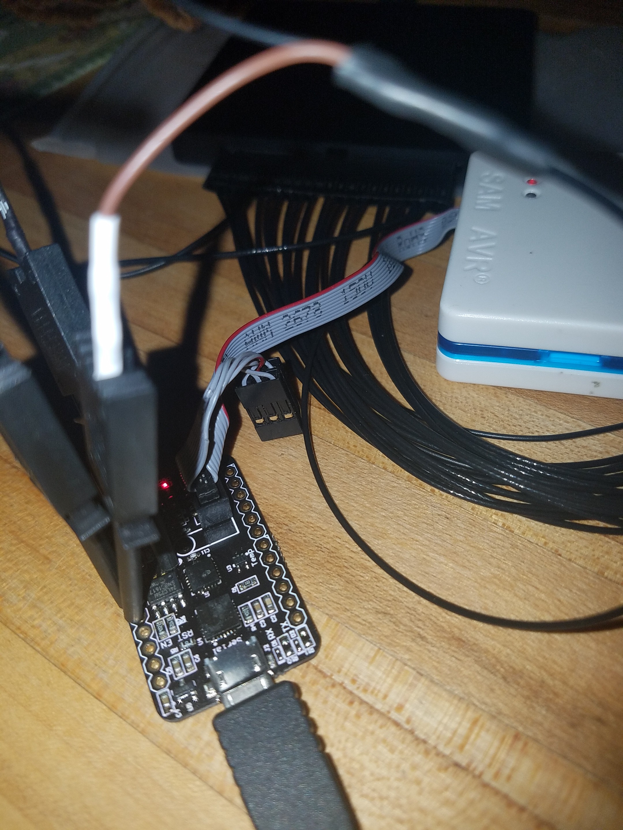
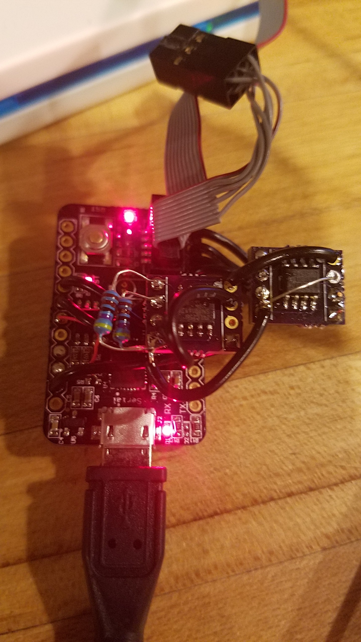
New board
![]()
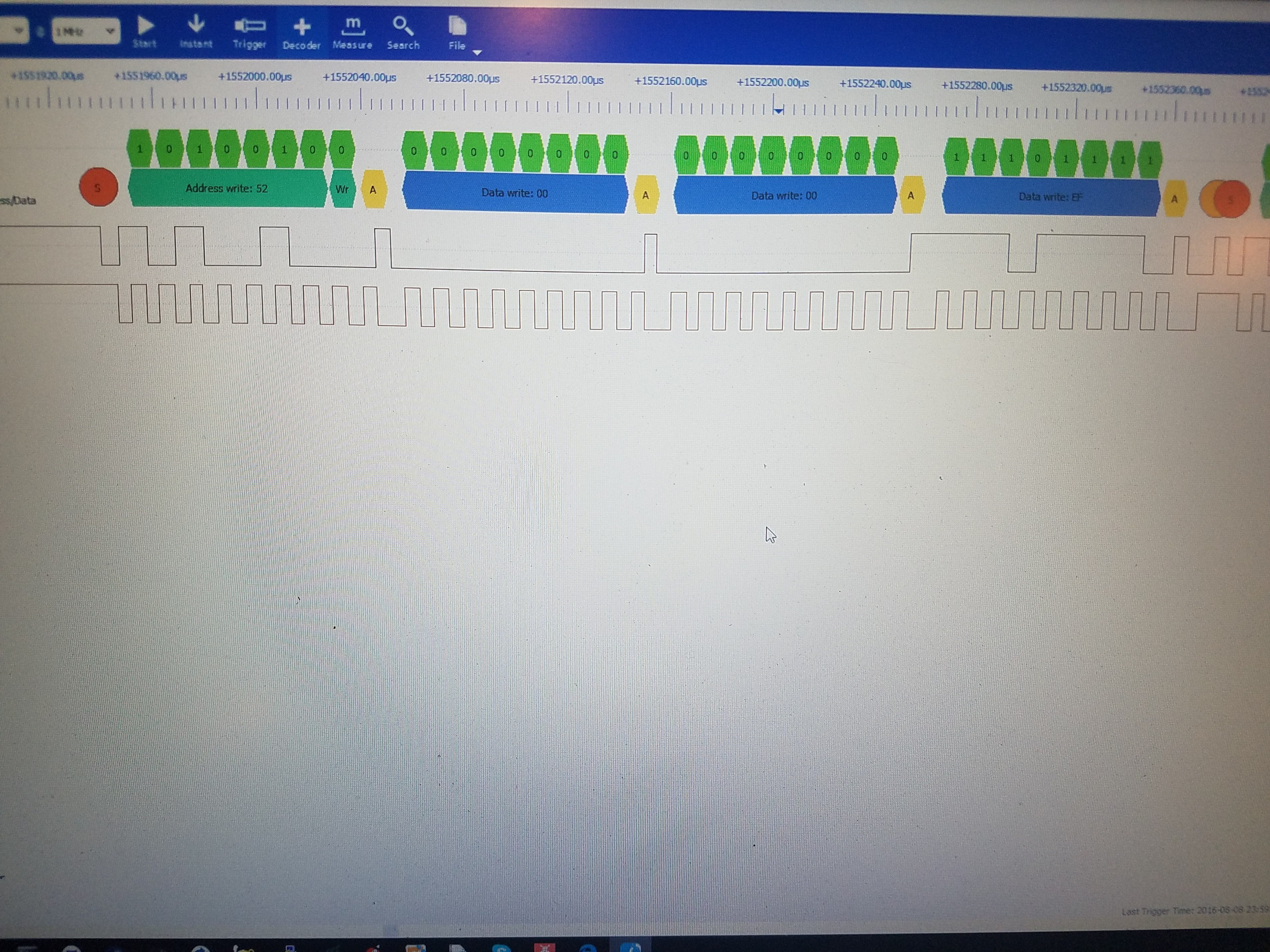
Writing 0xef
![]()
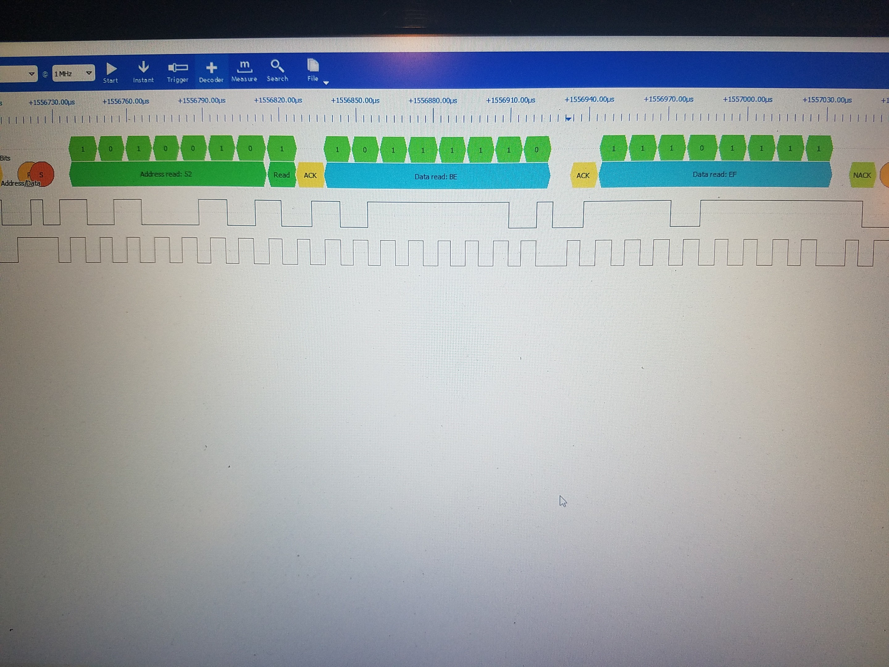
Reading beef, I wrote deadbeef to the eeprom earlier while testing the write byte functions.
![]()
I'll update the repository and start nailing down the i2c library, as well as making a library for the 24lcxxx eeproms.
update #1
Seems I broke it again... but learned a bit about how the i2c module works. And also seemed to have sudo fixed it at the same time.
I was reading the datasheet for the 24lc256 wrong and read the 8 byte word section as a 16 byte word for some reason.
So (a reminder for me) to write a byte worth of data in byte right mode we need too.
/*address space is from 0x0000 to 0x7FFF */

/*write a byte of something*/
I2c_write_start (); //starts a write transaction [send start,address,and w/r bit]
I2c_write_byte (0x00); //write data address high byte.
I2c_write_byte (0x00); //write data address low byte address 0x0000 00000
I2c _write_byte (0xAA); //write one byte of data at the supplied address
I2c_write_stop (); //send stop bit.

/*read a byte from the eeprom.*/
i2c_write_start(); // this sends the address with a w bit
i2c_write_byte(); // write data address high byte.
i2c_write_byte(); // write data address low byte.
i2c_read(data,1); // sends address with r bit, read from the data register, this reads two bytes, needs to be fixed.

/*put it on the serial terminal.*/
uart_write_byte(data);
All of this should work, I just now added some functions to this block of code. As I was not sending the start address for the read command just the address and r bit. I will update more later. Once I get this working I will write a 24lcxxx library that uses this i2c library for easier commands.
update #2
I got the i2c library nailed down for now. And started on the generic eeprom library. So far I can write a 16 byte word or 8 bytes to the eeprom, I can read it back. I can page write to the eeprom, reading back the page is proving to be difficult for some reason. I need to split the i2c read function apart.
Data!
....phone corrupted my photos... I'll be back with some pics...
-
Code stuffs, and libraries
07/19/2016 at 07:58 • 0 commentsWell I've been on a debugging spree. This will be a small update.
New library's have been added to the DEV branch in the git repo.
clocks.c/h
Sets system clocks needed for USART and I2C they both now work in tandem at 8Mhz core clock, they should work with 48Mhz and 98Mhz as well both have arithmetic baud rate equations
globalDefinitions.c/h
This only has one function in it currently a pinmuxing function to set pins to the correct states for usart, i2c, and spin
usart.c/h
Added send string, that's about it.
i2c.c/h
This is a work in progress, it at least gets data on the lines. Now that I have the series of events figured out I will rewrite this library soon.
There are more library's as well mostly helper libraries atm.
DEV bootloader is broken.
I don't know currently what is wrong with the dev branch bootloader but some how it's broken, I'll fix this later. The master branch bootloader still works fine.
Not broken?
it would seem that my IDE is in a funny state with that project. Can't set hardware breakpoints, and it immediately goes into disassembly mode.
Other than that the bootloader still works.. I can't seem to figure out why it's grown by about 1kb.. less I'm forgetting I did something. Which may be the case..
other than that not much going on. Waiting for the new boards to get here.
-
I2C & testing SPI
07/17/2016 at 05:57 • 3 commentsFun with I2C and SPI..
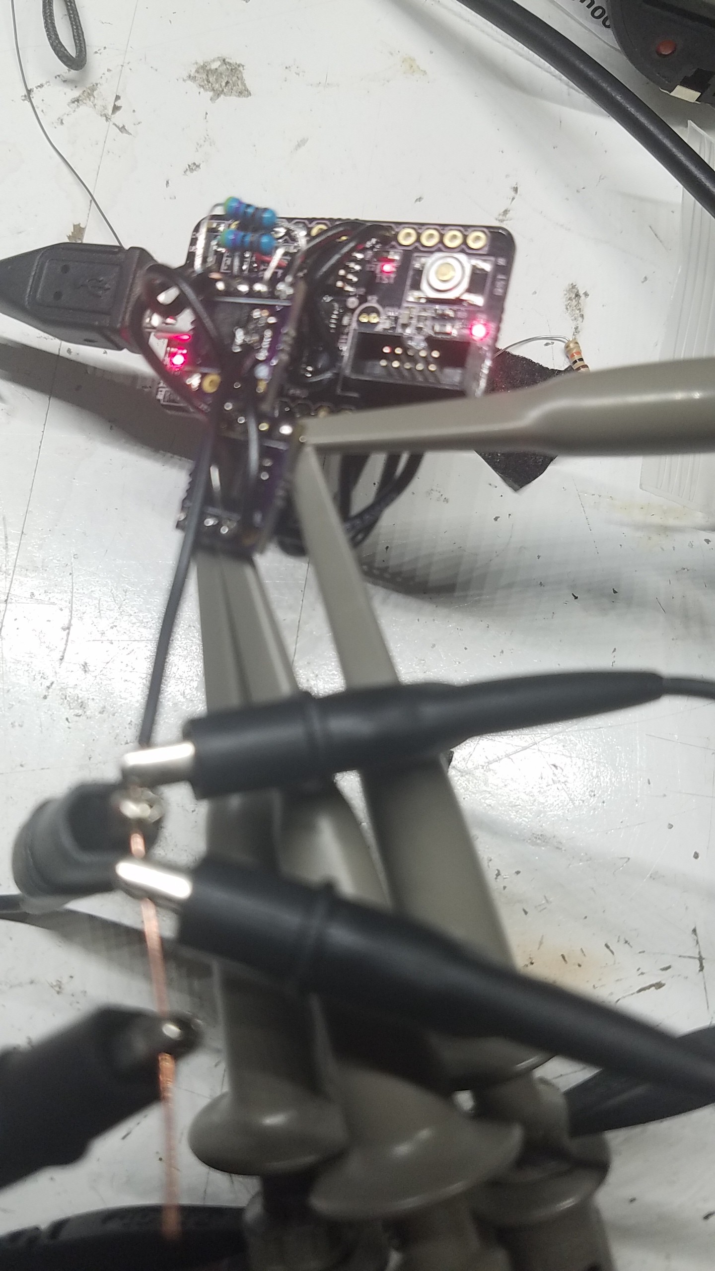
![]()
Good thing I ordered a bunch of tiny Soic 8 breakout boards :)
So it's been a while.. or a few days since my last post. Work8ng without asf and for that matter working with asf drivers is difficult especially when ones c foo in micro controllers is new and in ARM for that matter.
Also @Atmel Corporation I understand the need for a higher level c driver (kind of) but please provide some examples in pure c these micro's don't have alot of room and stuffing asf drivers into these things take quite a lot of space also the drivers are confusing..
here's how I2C is going:
I finaly managed to get the I2C module on SERCOM0 to configure properly, or so I think. I can somewhat talk to the eeprom but all I get back is garbage. So either something is not translating right (ie I am not processing the data properly) or its a baud rate issue etc. I have not thrown the micro into the scope yet.. I will look at the SCL line with a scope soon.
I created a function to scan the I2C bus and spit out the proper address of the device after an ACK is received. This seems to work but I get an address of 0xD0 when I expect an address of 0x50. This may be a pointer issue as well. I'll look into this tomorrow.
I2C update
I put the micro under the scope last night again for the I2C lines and they seem to be working. With a 24lc64 if I send it's address in write mode I get a ACK back(so says my scopes i2c decode functuon) and data is 0xFF witch I assume to be correct since the chips have never been programed.
I2C update 2:
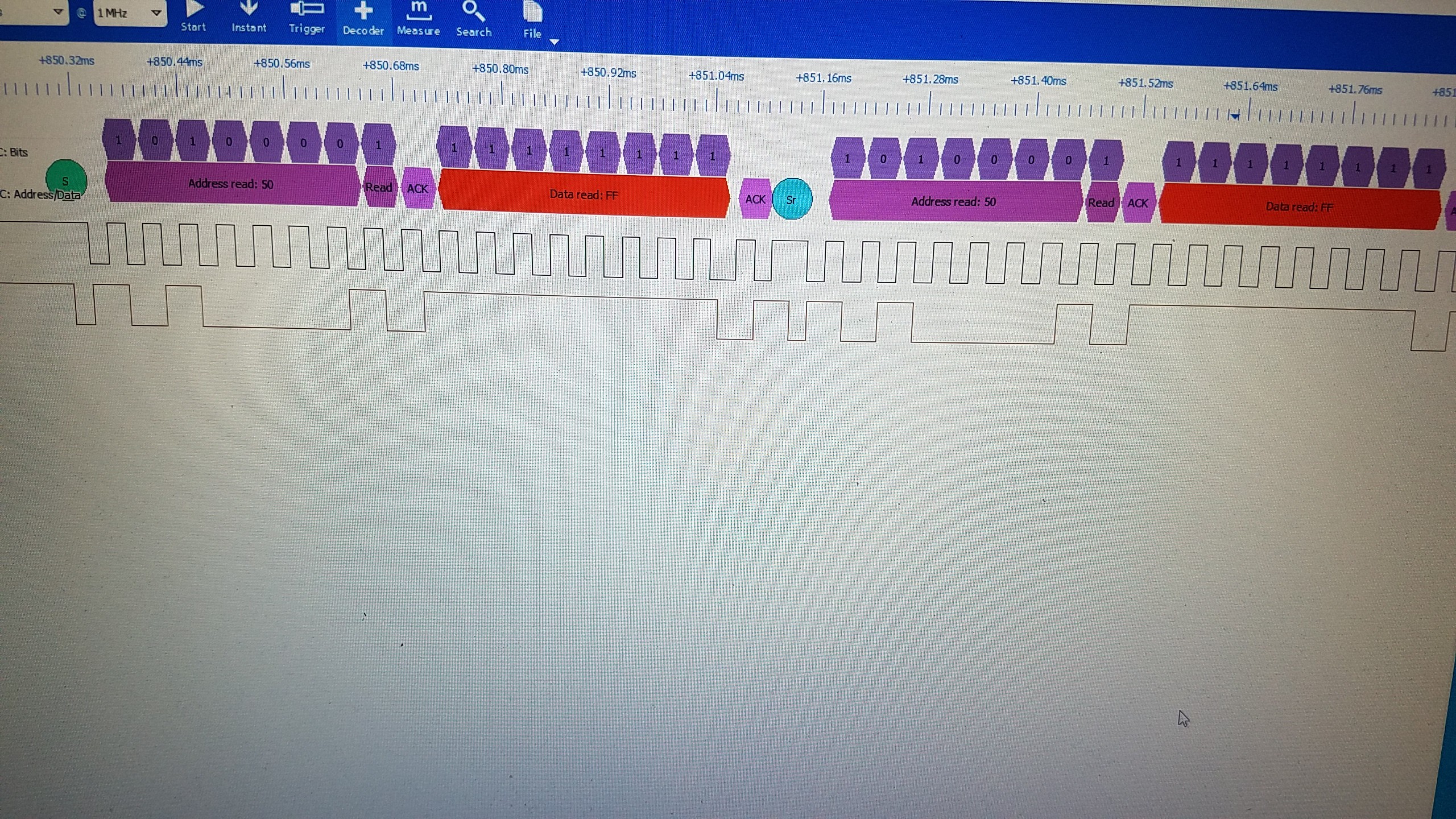
So far it seems that I2C is working. I hooked up the board to my logic analyzer and the data seems to be good. I'm continually sending a read address to the chip. This is what it looks like.
![]()
So all the ACK's are there and the data being sent back is understandably 0xFF this is what I would expect. Now to read reviews, write and read again to make sure the data is being stored.
@al1's SPI code:
al1 has managed to get a simple spi interface up and running and has successfully read the device id of some random flash chip he pulled from a board.
I am not having such good luck with this yet. I need to make sure the lines are acting properly. Everything is running from a base 1Mhz clock.
I get an rx event when I send the spi device a read instruction for its device id but nothing is in the rx buffer. Again it's probably my lack of reading the devices datasheet.
Update on SPI:
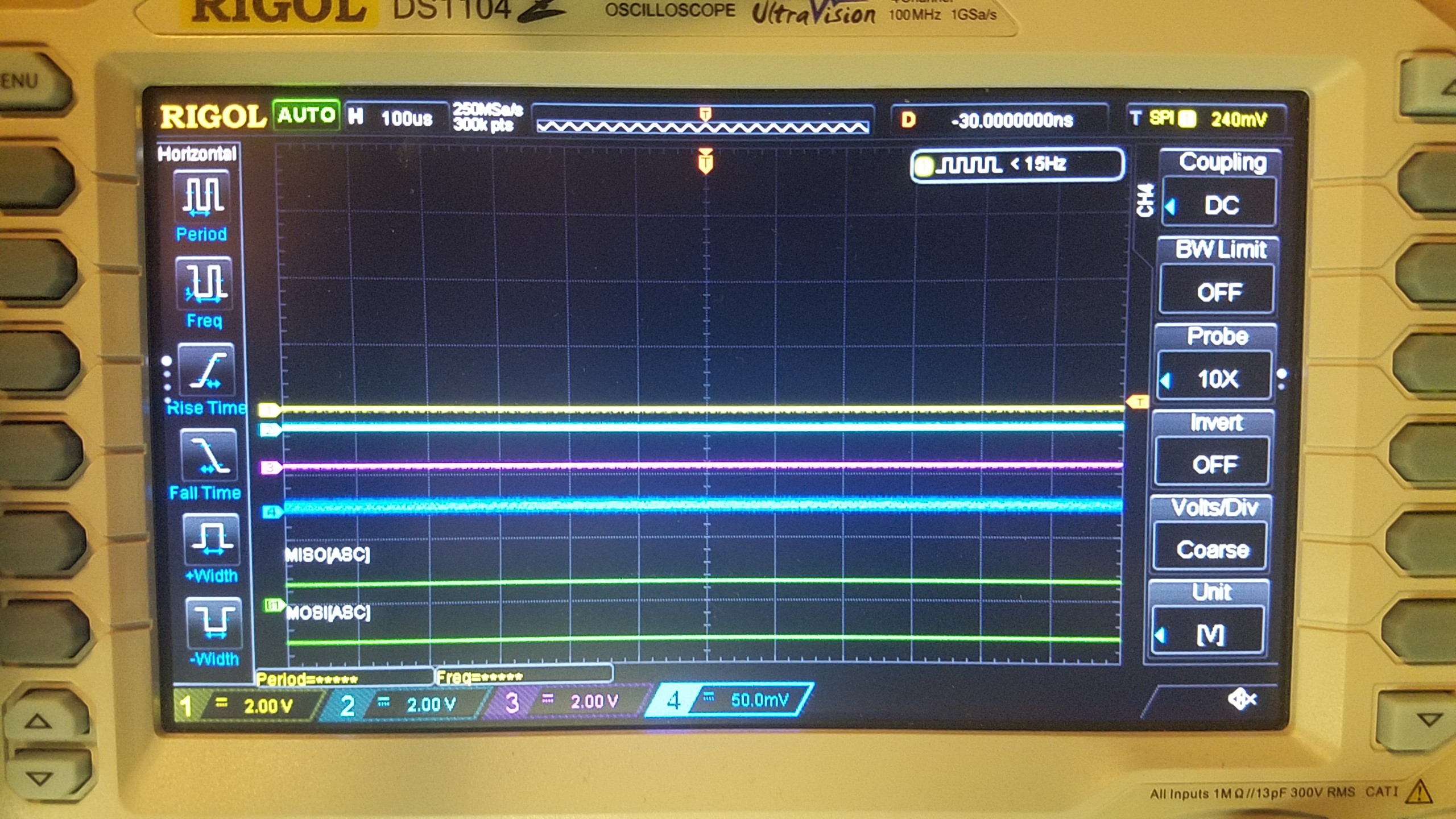
It would seem I'm not initializing the SPI pins properly. As I'm seeing jack on the scope...
![]()
Scope pic.
![]()
Getting nada, not even a wiggle.. I know I'm toggling the cs line.. somethings gata be up. Time to re program the chip.
Until next time.
-
Massive price hike? | Digi-Key
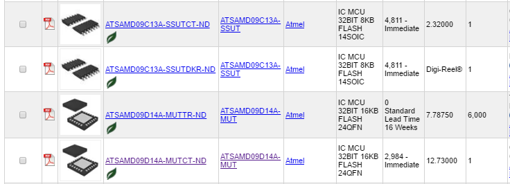
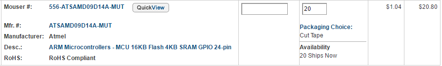
07/07/2016 at 03:39 • 5 commentsIt would seem someone has added an extra digit to the price of the samd09 chip.. it's now priced on Digi-key for $12.7 per quantities of 1... I bought less than a week ago at $1.27 per quantities of 1.
I tried talking to customer service about it but all they said was, it was a price hike due to manufacturer supply..
On the other hand Mouser still has them in stock for $1.22 per quantities of 1.
I'm a little confused, not mad, just confused. I hope its a glitch.
Notice anything funny?
![]()
My last purchase less than a week ago..
![]()
and currently Mouser pricing..
![]()
There in my cart..
anyway, I know this happens sometimes so don't troll my comments section, I just thought the price difference between the two was a little funny.
They were however nice enough to give me a quote that last for 13 days if I wanted to buy my kits again. I just may as the pricing is the same on mouser..
-
How to use the miniSam Serial Bootloader R1.3
07/06/2016 at 08:33 • 4 commentsSo I have managed to finish the bootloader, this includes the verification step in the python script.
Since I have been presented with some better information I will document the process of using the bootloader in more detail here.
Currently the bootloader version is 1.3 and can be found on github through the link on the left side of the page.
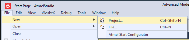
Setting up atmel studio 7
Start by creating a new project.
![]()
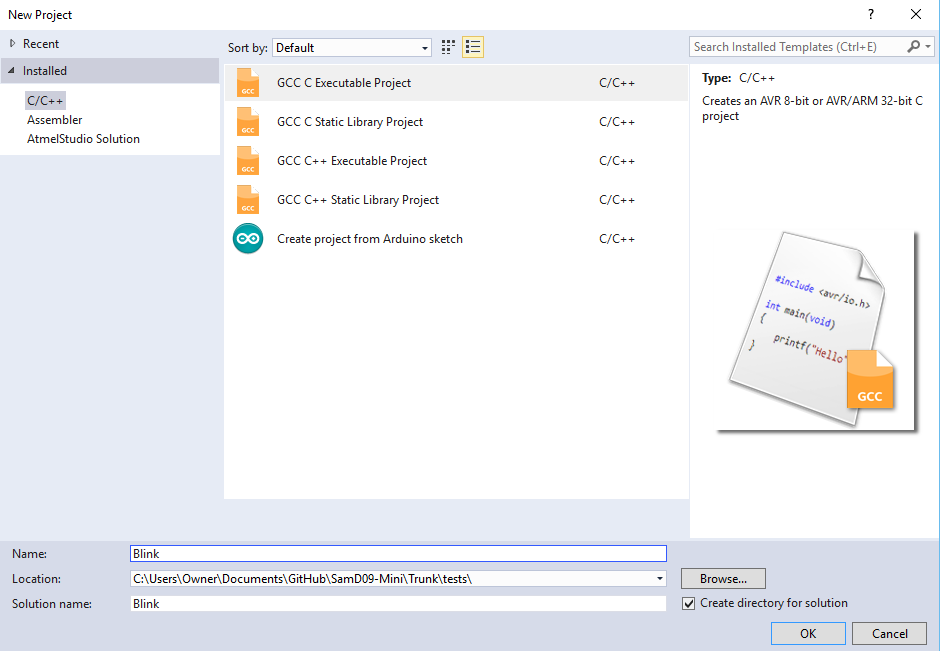
Name your project and select GCC C Executable Project.
![]()
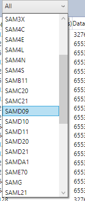
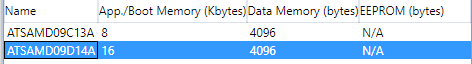
Select the proper chip family, in our case SamD09.
![]()
Select the chip present on the board, if you use @al1's board you would select ATSAMD09C13A. You will also need to wire the DTR pin from the ch340g(pin 15) to PA15, without this you will not enter bootloader mode. (hope its ok i used your board as an example.)
If using the MiniSam-Zero those connections are already made.
![]()
Once atmel studio has completed setting up your project. Right click on your project in the right panel and select properties. You should see this window. If you do not, you right clicked on the wrong item. usually the 2rd entry down.
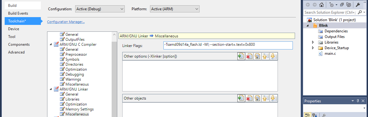
Now we need to tell the linker that we want the program to start at address 0x800. This will make the program compatible with the miniSam bootloader. Find ARM/GNU linker and select Miscellaneous. Copy the code given below into the field Linker Flags.
-Wl,--section-start=.text=0x800Then click ok. Now you can select your main.c in the right panel and start coding.![]()
a simple blink app.
#include "sam.h"

void init_TC1(void)
{
	//Thank you Al1 for sharing this timer setup.
	//setup clock for timer/counters
	REG_GCLK_CLKCTRL = GCLK_CLKCTRL_CLKEN | GCLK_CLKCTRL_GEN_GCLK0 | GCLK_CLKCTRL_ID_TC1_TC2;
	REG_PM_APBCMASK |= PM_APBCMASK_TC1;
	REG_TC1_CTRLA |=TC_CTRLA_PRESCALER_DIV8;			// prescaler: 8
	REG_TC1_INTENSET = TC_INTENSET_OVF;					// enable overflow interrupt
	REG_TC1_CTRLA |= TC_CTRLA_ENABLE;					// enable TC1
	while(TC1->COUNT16.STATUS.bit.SYNCBUSY==1);			// wait on sync
	NVIC_EnableIRQ(TC1_IRQn);							// enable TC1 interrupt in the nested interrupt controller
}

void TC1_Handler()
{
	REG_PORT_OUTTGL0 = (1 << 14);						// toggle led PA14
	REG_TC1_INTFLAG = TC_INTFLAG_OVF;					// reset interrupt flag - NEEDED HERE!
}

int main(void)
{
    /* Initialize the SAM system */
    SystemInit();
	init_TC1();											//init the clock.
	REG_PORT_DIR0 = (1 << 14);							//set the direction to output of PA14

    while (1)
    {
    }
}
This code should blink the on board led at 1hz. Here's how to upload it to the miniSam bootloader.Uploading.
As a note, the python script requires that you have python 2.7 installed as well as pyserial. Python 2.7 download. This link is directly from python.org's download section.
Currently the miniSam bootloader uses a python front end, I did not code this entire front end. This front end came with the suggested non working bootloader on a forum post and I updated it and modified it. So i can not take credit for this one. I will take credit for the modifications though :)
open a command line and navigate to the bootloader directory like so.
![]()
The python script you will be using is called upload.py instead of what is currently in the picture. The options are -c com# -b baudrate -i yourfilename.bin
If you have entered all of that properly you will presented with a quick question.
![]()
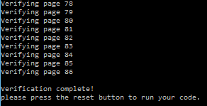
This question will ensure the miniSam bootloader is loaded and active. type y to proceed. Its fast but you will see a lot of programming page # and verifying page #
![]()
That's it your done!. Hopefully this is not to painful :), now you have no reason not to pick up a Arm micro (SamD variant at this point) and have some fun.
(Demo video will be here later. once its done uploading.)
I will be making some mini libraries I think, maybe. I'll see whats already out there.
until next time stay happy, stay healthy, and keep hackin.
-
SamD09 Serial bootloader success!
07/04/2016 at 18:01 • 4 commentsFirst I would like to give a big thanks to @Philip from #OSHChip V1.0 for helping me late into the night debuging the bootloader. He is an awsome dude with a wealth of knowledge. If you get the chance say hi.
What does it do!
The bootloader allows one to upload a "sketch/app/code" if you will, in the form of a .bin file to the samd09 while preserving the bootloader as well.
How does it function?
The bootloader (this one in general) resides at Non Volatile ram address 0x00000000. This may change at a later date. The user application gets uploaded via a python front end to address 0x00000800. Once the bootloader is done writing the user code and the verification process finishes (still working on this) the bootloader rebases the stack pointer, provides an offset to the vector tables and resets to the new program address at 0x00000800.
The verification process currently fails with the python script. This is an unknown bug atm but the program that is flashed vs the program that is created using Atmel Studio 7 are identical and works well.
How to use it.
To use the bootloader you must first flash the micro with the bootloader (uart_bootloader_R1_0_current.hex or .bin, you choice. This has to be done with a jtagger. Once the bootloader is flashed it should reside in the nvm at least until a full chip erase is issued.
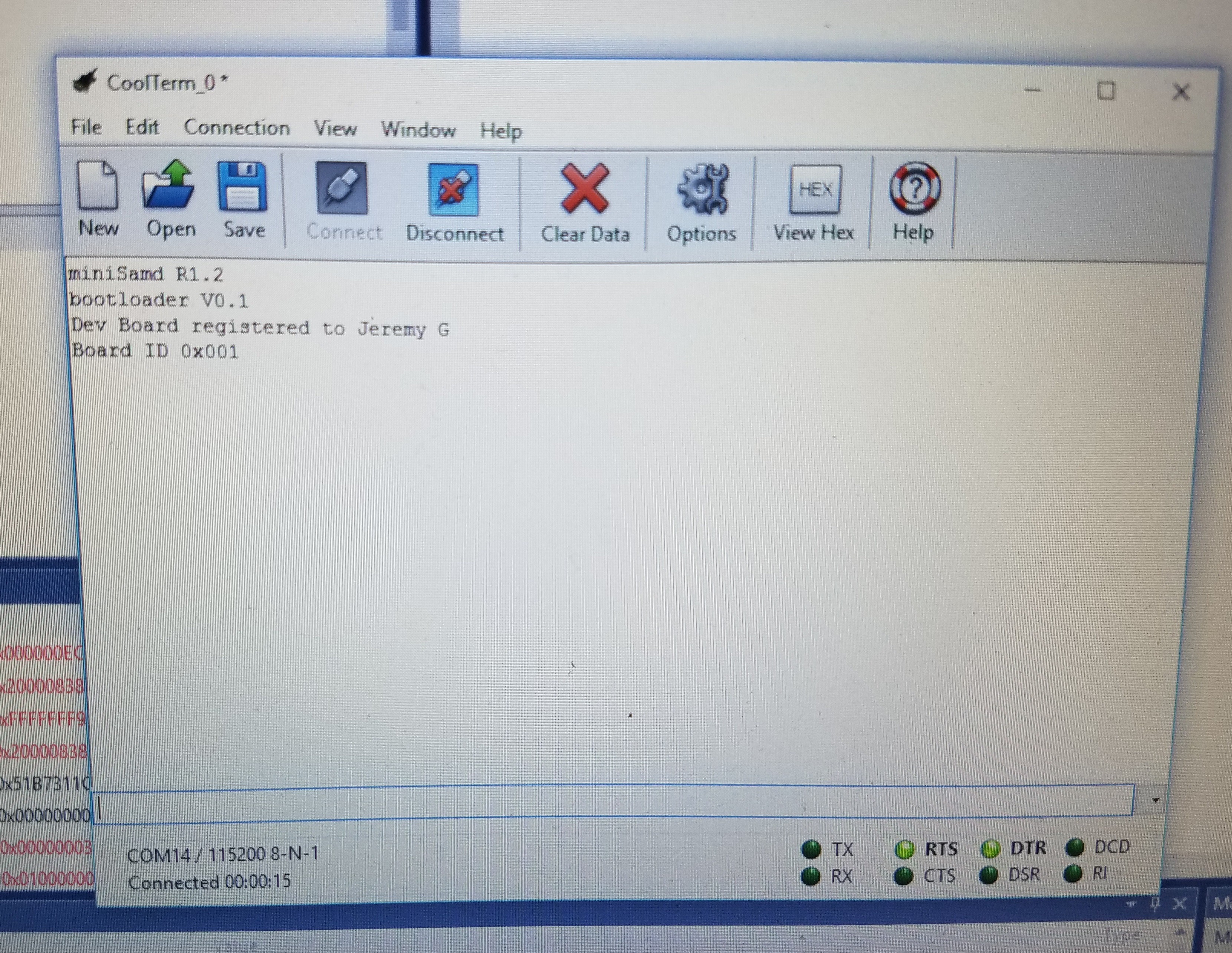
You can load the firmware using Atmel studio 7 with the provided workspace. Once flashed you can open a coms window (i use coolterm) set the com port to the cp2102 device, set the baud rate to 115200 and press connect. After connecting you may need to press the reset button on the micro, you will see the test led light up to let you know you are in bootloader mode.
if you type i and hit enter you should be presented with something like this. Mind you this is a dev version so yours may look a little different.
![]()
Creating "Apps" for the miniSam-Zero.
Using Atmel studio 7, select a new C based project. select the ATSAMD09d14 chip when asked. Atmel studio will load all the necessary files into your project. Its 4 files I believe plus the main.c file.
In the right hand panel you will see a folder called device startup, expand this folder and delete the file called samd09d14a_flash.ld. Then right click that folder and select add->add existing-> then select the samd09d14a_flash.ld that is in the github repo.
This ld file tells the compiler to compile your project starting at address 0x00000800. This helps us keep the vector tables and addresses straight when the program runs on top of the bootloader.
Now make your blinky led program or whatever it is you want to try (there are a few example projects in the repo.) and open a cmd prompt.
navigate to
\SamD09-Mini\Trunk\Bootloader\R1_0_current\PythonFrontEnd\
the python script is how you upload your code to the micro.
type
python upload.py -c com# -b 115200 -i yourfilename.bin
This will start the upload process, its pretty fast. Once that is finished the micro should reset by itself and start running your program. If not simply press the reset button and that should do it.To get back into bootloader mode (I will fix this.) run the python script the same time you release the reset button on the micro. you will know that you are in bootloader mode if the red led on PA14 is on.
Conclusion.
So far this has been an awesome learning experience. ~2-3 weeks ago I had absolutely no experience with arm processors. Now I'm hooked. There a little tricky at first to get used to but that's mainly due to the arduino IDE... we won't get into that now.
When I get time I will upload a video of how the process works. I know most people here know how a bootloader works. But for me I didn't really understand how a bootloader worked until I created one.
I will release the board files on both PCBs.io and oshpark.com the latter gives me a small credit to use for other projects. I will also make the miniSam-Zero available on my tindie store pre loaded with this bootloader.
The code and example projects are available on my github repo, linked on the side of the project page.
Until next time, stay happy, stay healthy, and keep hackin.
-
Bootloader woes..
07/02/2016 at 01:32 • 0 commentsLets take a look at some code. Maybe I can get some help with this as I have been beating my head against the desk trying to get this to work. I think I am almost there.
/*
 * main.c
 *Project:		miniSam USART bootloader.
 *Author:		Weistek Engineering (jeremy G.)
 *website:		www.weistekengineering.com
 *date:			06-29-2016f
 *Summery:		Modified version of the Samd10 bootloader.
 *				If PA15 bootpin is held low, micro will enter USART bootloader mode.
 *				if PA15 is high, micro runs user program if there is one at new start
 *				memory. Look at APP_START for start location of user flash.
 *
 *Important pins : 	UART pins [PA25 PAD3 -> TXd, PA24 PAD2 -> RXd]
 *					Boot En Pin PA15: enabled boot on reset when DTR pin LOW. Change to PA27?
 *					USART reset pin -> RTS -> RST PIN#. Used to reset the micro when
 *					Serial is plugged in, pulse RTS LOW. Almost arduino esqe.
 *
 *Update:			fixed write_nvm function, would fall to dummy handler.
 *
 *Todo:				need to fix Verify flash function, flash contents don't match.
 *					or they seem not to.
 */


#include "sam.h"
#include <component/nvmctrl.h>

#define PORTA 0 //Samd09 only has one port Port0

/* Application starts from 1kB memory - Bootloader size is 1kB */
/* Change the address if higher boot size is needed */
/*good site for quick conversions.*/
/*http://www.binaryhexconverter.com/hex-to-decimal-converter*/
#define APP_START	0x00000600 //This gives 1536 bytes of bootloader space.

/* Target application size can be 15kB */
/* APP_SIZE is the application section size in kB */
/* Change as per APP_START */
#define APP_SIZE	13	//This is how much flash memory is left for the application.

/* Flash page size is 64 bytes */
#define PAGE_SIZE	64	//used to read and write to flash.

/* Memory pointer for flash memory */
#define NVM_MEMORY        ((volatile uint16_t *)FLASH_ADDR)

/* Change the following if different SERCOM and boot pins are used */
#define BOOT_SERCOM			SERCOM1		//miniSam uses Sercom1 for USART
#define BOOT_SERCOM_BAUD	115200
#define BOOT_PORT			PORTA
#define BOOT_PIN			15 //14		//PA15 for bootloader en, toggled by the python script. or DTR from serial coms.

#define div_ceil(a,b)(((a)+(b)-1)/(b))			//extracted function from samd_math.h <- something like that.

/* SERCOM USART GCLK Frequency */
#define SERCOM_GCLK		8000000UL		//processor speed.
#define BAUD_VAL	(65536.0*(1.0-((float)(16.0*(float)BOOT_SERCOM_BAUD)/(float)SERCOM_GCLK))) //calculate baud rate from SERCOM_GCLK

uint8_t data_8 = 1;
uint32_t file_size, i, dest_addr, app_start_address;
uint8_t page_buffer[PAGE_SIZE];
uint32_t *flash_ptr;

//Version information.
uint8_t aVER[29] = {'m','i','n','i','S','a','m','d',' ','R','1','.','2',
					' ','b','o','o','t','l','o','a','d','e','r',' ','V','0','.','1'};


/*pin pad setup for SERCOM1 and USART*/
static inline void pin_set_peripheral_function(uint32_t pinmux)
{
    /* the variable pinmux consist of two components:
        31:16 is a pad, wich includes:
            31:21 : port information 0->PORTA, 1->PORTB
            20:16 : pin 0-31
        15:00 pin multiplex information
        there are defines for pinmux like: PINMUX_PA09D_SERCOM2_PAD1
    */
    uint16_t pad = pinmux >> 16;    // get pad (port+pin)
    uint8_t port = pad >> 5;        // get port
    uint8_t pin  = pad & 0x1F;      // get number of pin - no port information anymore

    PORT->Group[port].PINCFG[pin].bit.PMUXEN =1;

    /* each pinmux register is for two pins! with pin/2 you can get the index of the needed pinmux register
       the p mux resiter is 8Bit   (7:4 odd pin; 3:0 evan bit)  */
    // reset pinmux values.                             VV shift if pin is odd (if evan:  (4*(pin & 1))==0  )
    PORT->Group[port].PMUX[pin/2].reg &= ~( 0xF << (4*(pin & 1)) );
                    //
    // set new values
    PORT->Group[port].PMUX[pin/2].reg |=  ( (uint8_t)( (pinmux&0xFFFF) <<(4*(pin&1)) ) );
}

/*init USART module on SERCOM1*/
void UART_sercom_init()
{

	//Pmux eve = n/1, odd = (n-1)/2
	pin_set_peripheral_function(PINMUX_PA25C_SERCOM1_PAD3); // SAMD09 TX
	pin_set_peripheral_function(PINMUX_PA24C_SERCOM1_PAD2); // SAMD09 RX

	//apbcmak
	PM->APBCMASK.reg |= PM_APBCMASK_SERCOM1;

	//gclk config
	GCLK->CLKCTRL.reg = GCLK_CLKCTRL_ID(SERCOM1_GCLK_ID_CORE) | GCLK_CLKCTRL_GEN(0) | GCLK_CLKCTRL_CLKEN;

	//Config SERCOM1 module for UART
	SERCOM1->USART.CTRLA.reg = SERCOM_USART_CTRLA_MODE_USART_INT_CLK | SERCOM_USART_CTRLA_DORD | SERCOM_USART_CTRLA_RXPO(0x3) | SERCOM_USART_CTRLA_TXPO(0x1);

	SERCOM1->USART.CTRLB.reg = SERCOM_USART_CTRLB_RXEN | SERCOM_USART_CTRLB_TXEN | SERCOM_USART_CTRLB_CHSIZE(0);

	SERCOM1->USART.BAUD.reg = BAUD_VAL;//65535.0f * (1.0f - (float)(16*(float)(9600)/(USART_BAUD_MODIFIER_SLOW))); //This gets the miniSam exactly at 9800 baud.
	/* for 115200 baud compiler does not like this.*/
	//SERCOM1->USART.BAUD.reg = 65535.0f * (1.0f - (float)(16*(float)(USART_BAUD_MODIFIER_FAST)/(8000000)));

	SERCOM1->USART.CTRLA.reg |= SERCOM_USART_CTRLA_ENABLE;

}

/* interrupt handler for Sercom1 USART */
void SERCOM1_Handler()  // SERCOM1 ISR
{
	uint8_t buffer;
	buffer  = SERCOM1->USART.DATA.reg;
	while(!(SERCOM1->USART.INTFLAG.reg & 1)); // wait UART module ready to receive data
	SERCOM1->USART.DATA.reg = buffer;               // just sent that byte aback
	while(!(SERCOM1->USART.INTFLAG.reg & 2)); // wait until TX complete;
}

//this will be replaced with UART_sercom_simpleWrite function.
void uart_write_byte(uint8_t data)
{
	while(!BOOT_SERCOM->USART.INTFLAG.bit.DRE);
	BOOT_SERCOM->USART.DATA.reg = (uint16_t)data;

}

void UART_sercom_simpleWrite(Sercom *const sercom_module, uint8_t data)
{
	while(!(sercom_module->USART.INTFLAG.reg & 1)); //wait UART module ready to receive data
	sercom_module->USART.DATA.reg = data;
	while(!(sercom_module->USART.INTFLAG.reg & 2)); //wait until TX complete;
}

//this will be replaced with UART_sercom_simpleRead function.
uint8_t uart_read_byte(void)
{
	while(!BOOT_SERCOM->USART.INTFLAG.bit.RXC);
	return((uint8_t)(BOOT_SERCOM->USART.DATA.reg & 0x00FF));
}

void nvm_erase_row(const uint32_t row_address)
{
	/* Check if the module is busy */
	while(!NVMCTRL->INTFLAG.bit.READY);
	/* Clear error flags */
	NVMCTRL->STATUS.reg &= ~NVMCTRL_STATUS_MASK;
	/* Set address and command */
	NVMCTRL->ADDR.reg  = (uintptr_t)&NVM_MEMORY[row_address / 2];
	NVMCTRL->CTRLA.reg = NVMCTRL_CTRLA_CMD_ER | NVMCTRL_CTRLA_CMDEX_KEY;
	while(!NVMCTRL->INTFLAG.bit.READY);
}

void nvm_write_buffer(const uint32_t destination_address, const uint8_t *buffer, uint16_t length)
{

	/* Check if the module is busy */
	while(!NVMCTRL->INTFLAG.bit.READY);

	/* Erase the page buffer before buffering new data */
	NVMCTRL->CTRLA.reg = NVMCTRL_CTRLA_CMD_PBC | NVMCTRL_CTRLA_CMDEX_KEY;

	/* Check if the module is busy */
	while(!NVMCTRL->INTFLAG.bit.READY);

	/* Clear error flags */
	NVMCTRL->STATUS.reg &= ~NVMCTRL_STATUS_MASK;

	uint32_t nvm_address = destination_address / 2;

	/* NVM _must_ be accessed as a series of 16-bit words, perform manual copy
	 * to ensure alignment */
	for (uint16_t k = 0; k < length; k += 2)
	{
		uint16_t data;
		/* Copy first byte of the 16-bit chunk to the temporary buffer */
		data = buffer[k];
		/* If we are not at the end of a write request with an odd byte count,
		 * store the next byte of data as well */
		if (k < (length - 1)) {
			data |= (buffer[k + 1] << 8);
		}
		/* Store next 16-bit chunk to the NVM memory space */
		NVM_MEMORY[nvm_address++] = data; //<- this supposedly writes the data to the location specified.
                //This is required in order for the NVM write to be accepted. or so it seems.
                NVMCTRL->CTRLA.reg = NVMCTRL_CTRLA_CMD_WP | NVMCTRL_CTRLA_CMDEX_KEY;
	}
	while(!NVMCTRL->INTFLAG.bit.READY);
}

int main(void)
{
	/* Check if boot pin is held low - Jump to application if boot pin is high */
	//PORT->Group[BOOT_PORT].OUTSET.reg = (1u << BOOT_PIN); //<- works without this definition.

	PORT->Group[BOOT_PORT].PINCFG[BOOT_PIN].reg = PORT_PINCFG_INEN | PORT_PINCFG_PULLEN;
	if ((PORT->Group[BOOT_PORT].IN.reg & (1u << BOOT_PIN)))
	{
                //This seems to set app_start_address as 0xfffffff <- this is bad.
		app_start_address = *(uint32_t *)(APP_START + 4);
		/* Rebase the Stack Pointer */
		__set_MSP(*(uint32_t *) APP_START + 4);

		/* Rebase the vector table base address */
		SCB->VTOR = ((uint32_t) APP_START & SCB_VTOR_TBLOFF_Msk);

		/* Jump to application Reset Handler in the application */
		asm("bx %0"::"r"(app_start_address));
	}

	/* Make CPU to run at 8MHz by clearing prescalar bits */
        SYSCTRL->OSC8M.bit.PRESC = 0;
	NVMCTRL->CTRLB.bit.CACHEDIS = 1;

	/* Config Usart */
	UART_sercom_init();
	info(); //display version info on usart.
    while (1)
    {
        data_8 = uart_read_byte();
		if (data_8 == '#')
		{
                        //this works fine.
			uart_write_byte('s');
			uart_write_byte((uint8_t)APP_SIZE);
		}
		else if (data_8 == 'e')
		{
			/*this has been fixed, it no longer fails to
			a dummy handler*/
			for(i = APP_START; i < FLASH_SIZE; i = i + 256)
			{
				nvm_erase_row(i);
			}
			dest_addr = APP_START;
			flash_ptr = APP_START; //0x600
			uart_write_byte('s');
		}
		else if (data_8 == 'p')
		{
                        //with adding the NVMCTRL cmd this seems to work.
                        //only problem is after the micro resets, the data is gone...
			uart_write_byte('s');
                        //Page_Size is 64, the python script sends a page_size of 40?
                        //this used to read for(i=0;i<(PAGE_SIZE/4) /*64/4 = 16 <- good*/;i++)
                        //the old for loop would fall to a dummy handler as well this one does not.
			for (i = 0; i < PAGE_SIZE; i++)
			{
				page_buffer[i] = uart_read_byte();
			}
			nvm_write_buffer(dest_addr, page_buffer, PAGE_SIZE);
			dest_addr += PAGE_SIZE;
			uart_write_byte('s');
		}
		else if (data_8 == 'v')
		{
			/* now we get stuck here... varifing pages fails on the first page.
			don't know why.*/
			uart_write_byte('s');
			for (i = 0; i < (PAGE_SIZE); i++)
			{
                                //app_start_address grabs 0xffffff <- bad again. if we omit app_start_address
                                //and simply use uart_write_byte(SERCOM1,(uint8_t)(*flash_ptr>>8)); we get the proper
                                //data back... eventually for some reason we start at 0xBEC instead of 0x600+4..
                                //what am i missing? someone told me we need to do this
                                //app_start_address = &flash_ptr <- to de reference the flash_ptr. have not tried this yet.
				app_start_address = *flash_ptr;
				//uart_write_byte((uint8_t)app_start_address);
				UART_sercom_simpleWrite(SERCOM1,(uint8_t)(app_start_address >> 8));
				//uart_write_byte((uint8_t)(app_start_address >> 8));
				UART_sercom_simpleWrite(SERCOM1,(uint8_t)(app_start_address >> 16));
				//uart_write_byte((uint8_t)(app_start_address >> 16));
				UART_sercom_simpleWrite(SERCOM1,(uint8_t)(app_start_address >> 24));
				//uart_write_byte((uint8_t)(app_start_address >> 24));
				flash_ptr++;
			}
		}
    }
}

void info()
{
	uint8_t i;

	for(i = 0;i<=29;i++)
	{
		UART_sercom_simpleWrite(SERCOM1,aVER[i]);
	}
}
This code is heavily commented and works, just not in the way it should to accomplish a functional bootloader. the start of our app is at 0x600+4 this is the address that nvm_write() should write the data too, instead we write at 0xBEC ? I don't know why.
if we assign a uint32_t variable with *flash_ptr witch should be at 0x600 we actually get 0xffffff <- this is wrong or at least i see it as wrong.
I should have more time to mess with this tonight, I will try de-reference the flash pointer and also try setting the APP_START variable to 0xBEC and see if that helps. It may be that the bootloader sections are set in stone and if you go over the limit for the next lowest allowed size it automatically moves to the next largest space so 0x600 = 1536 where as the program wants to write data too 0xBEC = 3052 thats 3kb from the start of the address space. this makes no sense as the datasheet says bootloader address spacing is from 0, 256, 512, 1024, 2048...
any information. would be great. This post may seem a bit haphaserd, it was a quick one.
Stay happy, stay healthy, and keep hackin.
-
USART bootloader
06/30/2016 at 19:06 • 0 commentsI don't know why I wanted a bootloader since I have the required jag tools to program the device without needing a bootloader. But this does work well as a learning experience, also if someone else wanted to mess about with the board then they wouldnt need a jtag programmer to do so.
I found a Serial boot loader for the samd10 Micro and gutted it. The usart write and read functions did not work all that well at least on my samd09. I fixed that with my own functions. The bootloader talks at 115200bps to a python script. That also came with with D10 boot loader. But it has been modified to toggle the boot pin so the micro enters bootloader mode on reset.
I ran into an issue when writing to user flash I'm pretty sure it was an overflow issue although the registers on the micro indicated that was not the case. The function would get to the end of the usable user flash and fall to a dummy handler function for interrupts that did nothing. This has been fixed, or so it seems.
My next issue is verifying the userr flash. This function always seems to spit out the incorrect data, so says the python script anyway. I need to look into this and see what's different about the memory space on the 09 va the 10 it seems that the page size is wrong.
Other than that the bootloader is staying around 1Kb in size. So that's nice it still leaves around 14~15Kb for programs. But that's what the EEPROM is for :) a little added space.
I'll have to do another board spin as now the boot loader has two new pin definitions. So hopefully R1.3 will be the final spin.
Stay happy, stay health, and keep hackin.
-
New spin.
06/29/2016 at 07:21 • 0 commentsI have fixed the issues with the current board and sent out for a new spin. This should be the final spin for this board.
Things I have managed to get working so far are USART, and working on I2C. Not having much luck on the I2C front (coding wise).
The EEPROM has been reduced to 64kbit (8Kbytes, should be plenty) to save on bom cost.
A resistor pad has been added to the cp2102 for a reset when serial coms have been activated i.e plugging in a usb cable. This will also need to be tested for reliability.
I will update the log with a parts list, and schematics soon.
The board will also be available in my Tindie store soon.
Stay healthy, stay happy, and keep hackin.
MiniSam-Zero
Tiny sameD09 dev board. (Zero has nothing to do with arduino, the name allows other boards in this line. namely -One, & -Two coming later.)