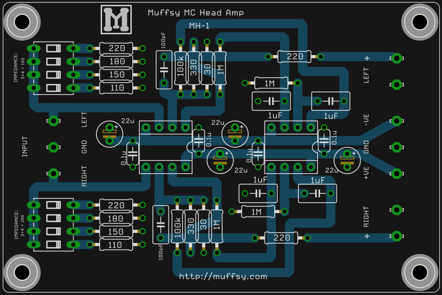
The final schematic is not entirely ready (the current version is added at the bottom of this project log anyway), here's a teaser in the form of a PCB rendering:

The rendering is done using Copper App (http://www.copper-app.com). Although they have added quite a few through hole components, the four-way dip switches for selecting the input impedance were not yet available.
Here's the first attempt at a PCB routing, with component values:
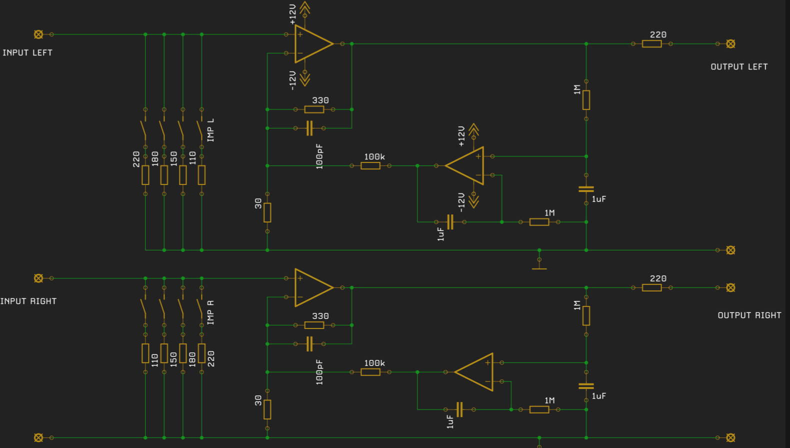
This is the current circuit schematic, on which the PCB is based:
Discussions
Become a Hackaday.io Member
Create an account to leave a comment. Already have an account? Log In.