The boards arrived this morning:
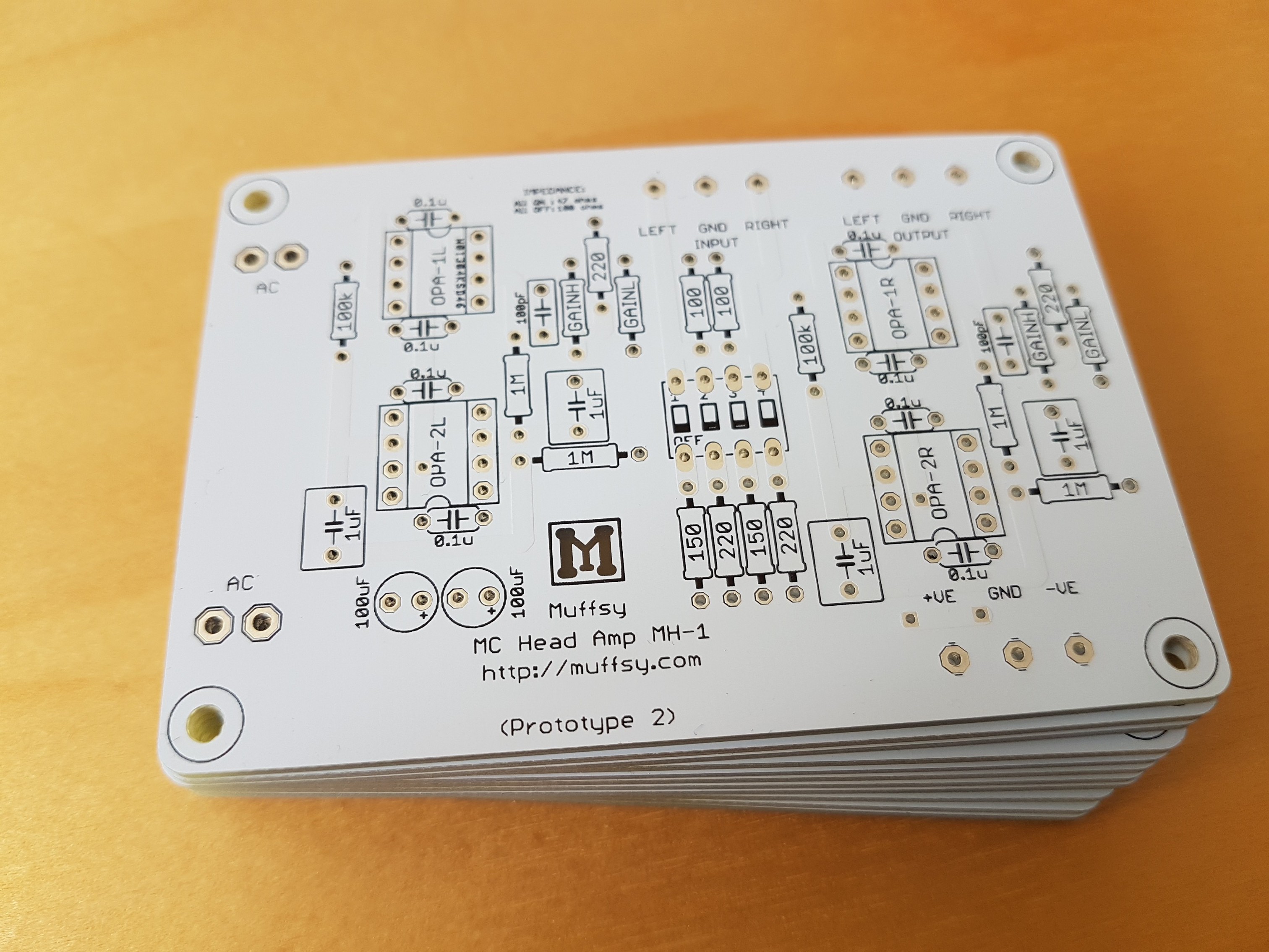
It's time to solder on, test, and see how the board fits in the enclosure.
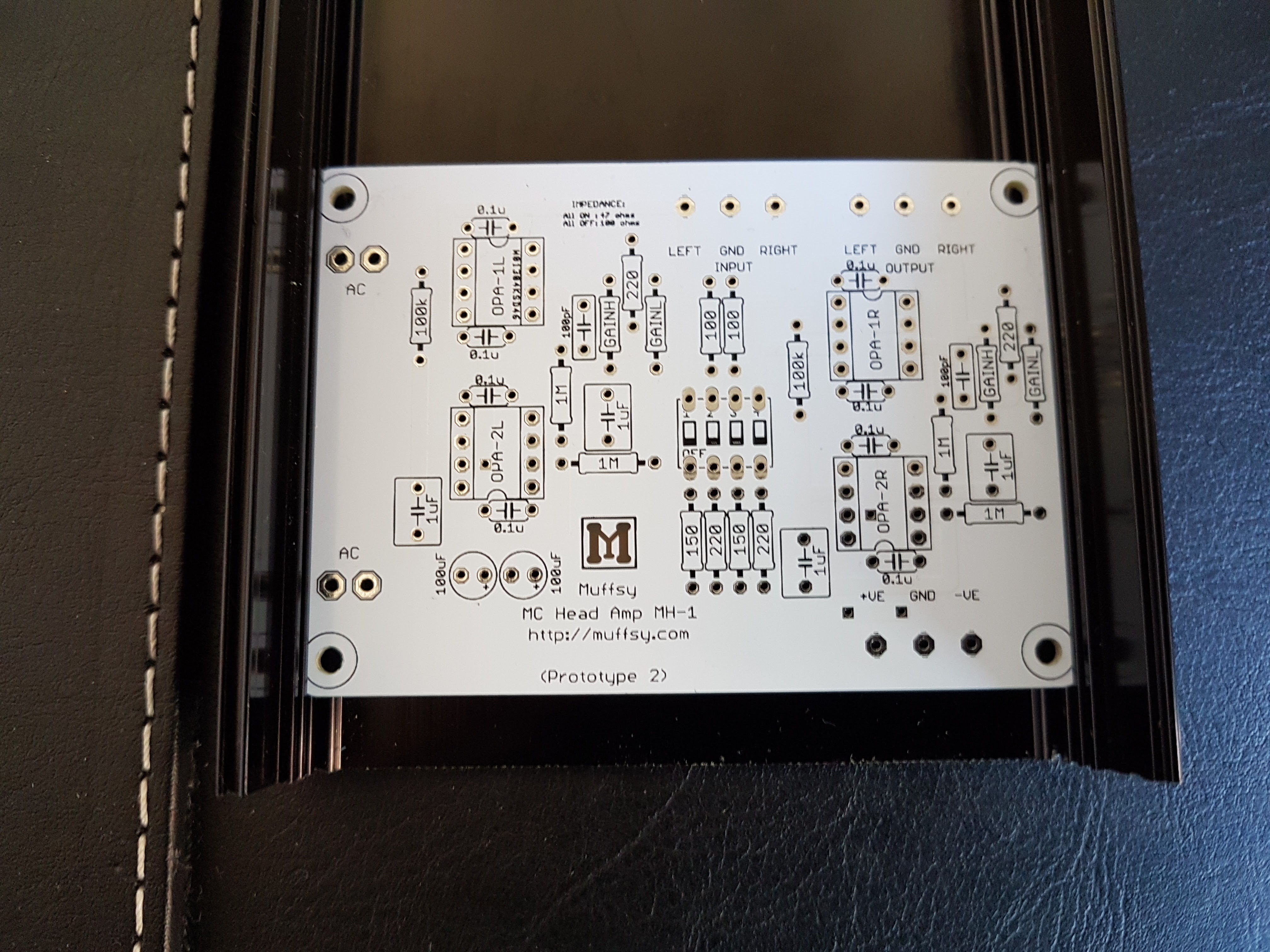
The AC pads on the left and the resistors on the right are a bit too close to the enclosure walls, there'll be some cosmetic changes in the next version.
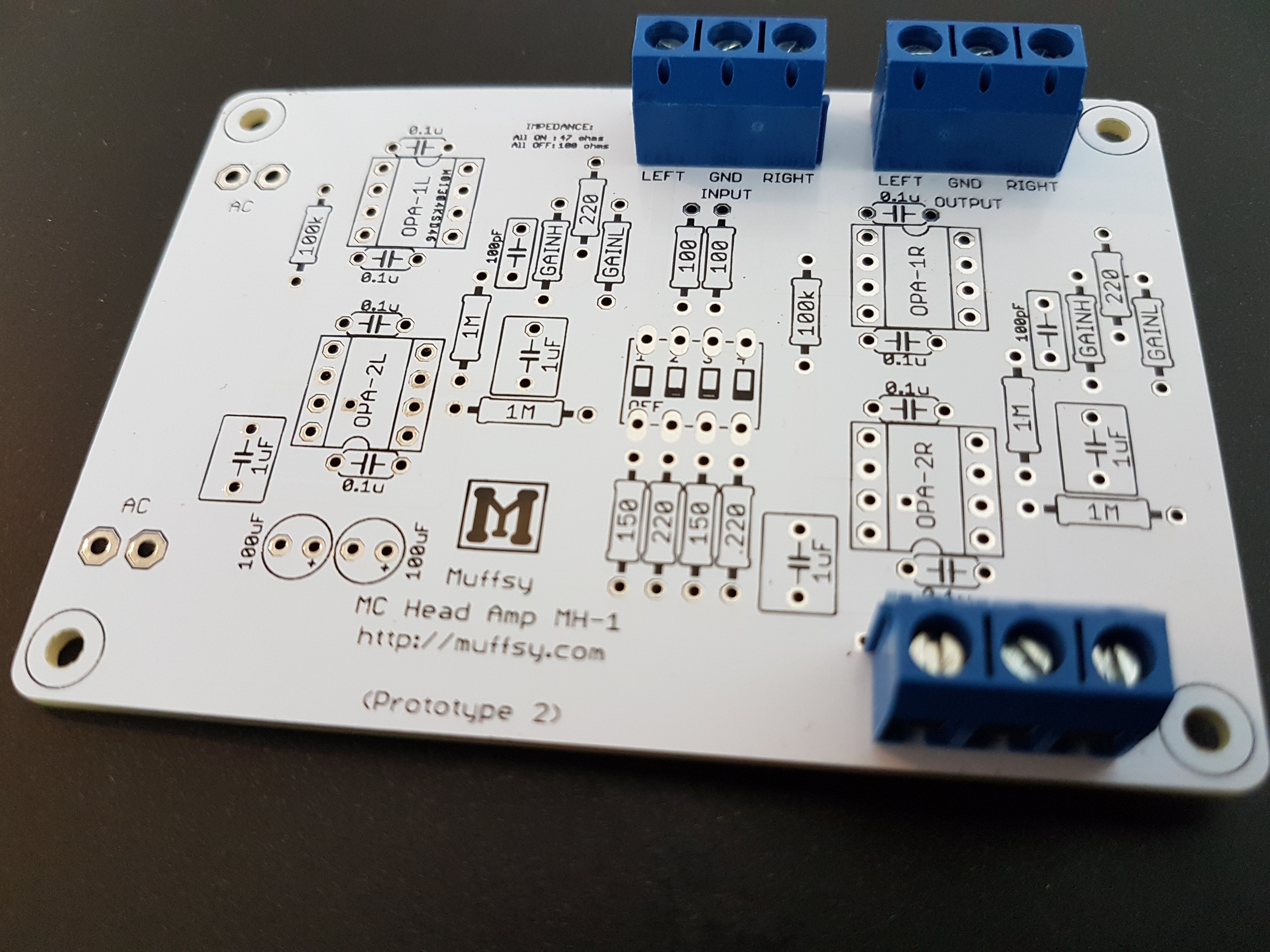
Here's the board with screw terminals, just to get an idea of how it will look. The inputs/outputs are on the far side (close to the back panel) and the power connects on the near side (close to the power supply):
Discussions
Become a Hackaday.io Member
Create an account to leave a comment. Already have an account? Log In.