Close
0%
0%

explorad - input device

A small box with 5 buttons and (hopefully) a touch wheel. Serial output.

Similar projects worth following
I'm building a handheld input device for my explorad (see below for a link to the main project) that has 5 buttons: left, up, right, down and enter. I hope to include a touch wheel as well, but I've never designed any touch input devices so that might fail.

This device can be used as a simple input device for many projects, and acts as a (more or less) standalone unit. It reads 5 buttons and a touch wheel (if I can get that to work), processes the readings and transmits a human readable string over an RS232 line at 9600 baud 8N1 whenever something happens. It is powered externally with 5 V.

I will add a LiPo battery and a charger circuit later, so that it can additionally be used as a power supply for the device it gives input to.

  • 1 × Plastic enclusure. Should be comfortable to hold with a flat top surface Mine is 102 x 61 x 26 mm
  • 1 × Teensy 2.0 AVR prototyping board
  • 5 × Push button Not too big.
  • 1 × A piece of perfboard
  • 1 × Copper tape I'll try to make a touch wheel with this

View all 10 components

  • OK, I skipped that other plot, but here's an even better one

    Christoph07/03/2014 at 21:58 0 comments

    I added load sharing to the charger so that the device can run off USB (or any other external 5V supply) or off the battery. Either external or internal power are then fed into a pololu 5V step up/down regulator. Here's a picture of the charger circuit and the explorad board:

    In the above picture, the battery is supplying power (the red wire from the Teensy is open, upper left corner). After a while (1h 15m), I connected the charger to the Teensy to give it 5V from USB, so it switched to that supply line and started charging:
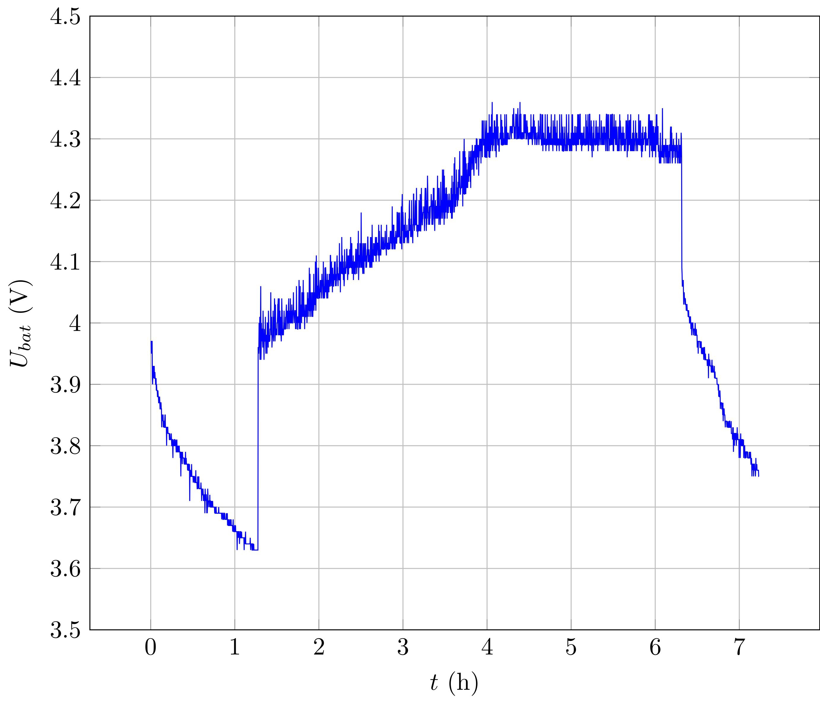
    It stopped charging after about 6h, but the device was still supplied from USB. So I disconnectd USB power again (6h 15m) and the battery was used again. The was no power loss in between, so I can connect or disconnect external power while the device is running.
    I have no idea why the readings were so flaky, but it might be due to the very old battery. I'll see if I have a newer one somewhere.

  • Started building the charger circuit

    Christoph07/01/2014 at 21:02 0 comments

    All parts are here, I can build the charger circuit.

    The first step was to build the charger - without load sharing - on a breadboard. These are the parts I used:

    • An old Siemens S65 phone battery: Li-Ion, 700 mAh. It has a third pin in addition to + and -, which is connected to an internal NTC (I think) to ground (I think). It can be used to measure the battery's temperature.
    • an MCP73832-2ACI-OT battery charger chip and capacitors for input and output,
    • a low-current LED with a 1k resistor to indicate the charging status,
    • a 10k resistor to set the charging current to 100 mA,
    • a 10k pull-up between the battery's thermistor and 5V. Together, they are a voltage divider that is used to generate an input signal for an ADC.

    An AVR is measuring both the battery voltage and the thermistor divider voltage and outputs them over USB serial, to be logged on my computer. The battery is currently charging and I'll post a plot of that later if it doesn't catch fire until then. To make sure that the battery temperature rises during charging, I've placed it in my computer's warm exhaust air.

  • Moved to enclosure, hardware seems to work

    Christoph06/08/2014 at 20:38 0 comments

    I finished the enclosure by adding cutouts for a switch, the USB cable, and an extra reset/program button for the Teensy.

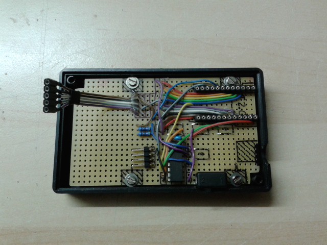
    The perfboard is also finished for now, I'll only need to modify it again when I add the touch wheel. The buttons are now connected to a PCF8574A, because I might need I²C later anyway. Here's a picture without the Teensy and cables:

    And one with the Teensy and the cable that goes to the main device:
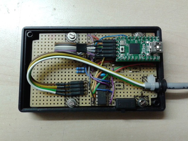
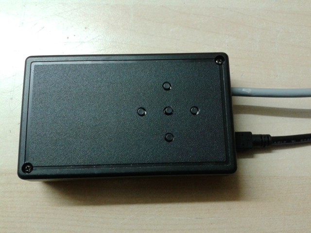
    The small switch in the lower right corner will later be used to enable power.

    When the code really locks up, the Teensy downloader can't just reset the board over USB, so I added an extra reset/program button that can be accessed without opening the enclosure. It sits next to the user buttons and can be pressed through a small hole in the front which was not yet drilled in this picture:

    A very simple piece of example code has shown that everything is hooked up correctly (I can read the buttons).
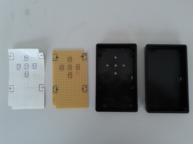
  • Drilled perfboard and enclosure

    Christoph06/03/2014 at 13:35 0 comments

    I cut out a piece of perfboard to fit into an enclocure that is comfortable to hold in one hand, added mounting holes, decided where the buttons should be and drilled holes for them into the enclosure:The buttons will be through-hole devices, but mounted on the soldering side. That allows me to put the microcontroller and all support circuitry on the other side and when I push the buttons, their solder joints are pushed into the PCB instead of being pulled out (I've made bad experience with that).
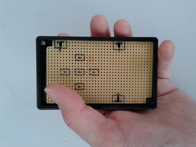
    (The image should be upright...)

  • Moved buttons from eplorad to input device

    Christoph05/31/2014 at 13:03 0 comments

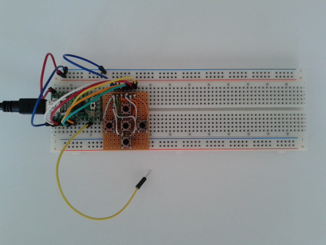
    Today I removed the small buttons board from the explorad breadboard to a new breadboard with a Teensy 2.0:

    The yellow wire is the Serial1 Tx line (TTL, nothing fancy like RS232).
    The code currently just debounces the buttons and sends a short string over Serial1 at 9600 8N1. Example:

    b 0 0

    means that button 0 (left) has been pressed. No further string is sent for that button until it is pressed again. The second '0' means that this was an "initial" press, not a software repeat (which I plan to implement), so

    b 0 1

    would mean that button 0 was pressed, and the software inserted a repetition.

    There's still plenty of space for more hardware, like the LiPo charger, touch input hardware, and so on.

  • I might add a LiPo battery and charger circuit to this

    Christoph05/28/2014 at 22:22 0 comments

    The explorad or the input device must contain a power supply. As the whole device will be mobile, I need to charge it without too much hassle. While the explorad should stay mounted on the telescope, the input device can be detached.

    If the input device contains the LiPo battery, it's probably easier to charge the battery. There are small charger ICs for that purpose, and I even found an example of a circuit that uses the MCP73831 and provides load sharing - it can charge the battery from USB and at the same time supply the load:

    http://blog.zakkemble.co.uk/a-lithium-battery-charger-with-load-sharing/

    As the load requires 5V, I will need a step-up converter. They are readily available as small modules. Furthermore, the Teensy 2.0 can be used to control charging and send status information to the main device.

View all 6 project logs

Enjoy this project?

Share

Discussions

Similar Projects

Does this project spark your interest?

Become a member to follow this project and never miss any updates