matthewreed
-
Prototyping New Modules
08/01/2017 at 16:19 • 0 comments![]()
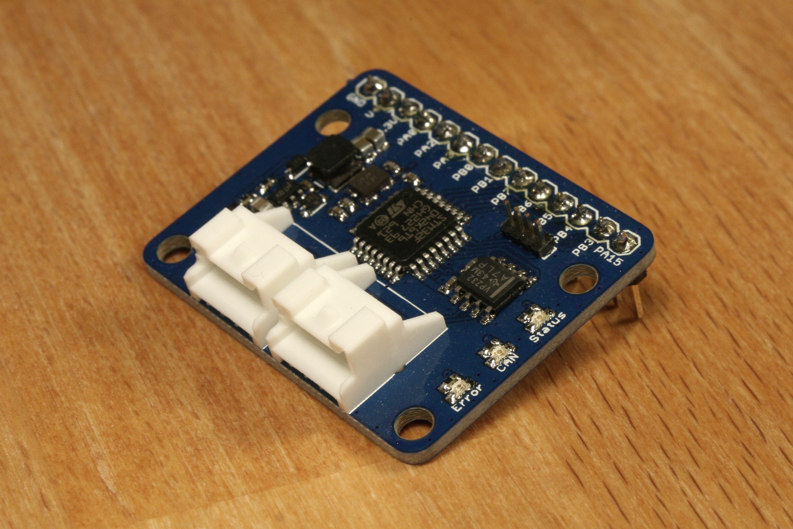
ProtoModule is a HydroBot module designed to easily develop and test new monitoring or control functions that may someday go into a HydroBot module. It has 11 GPIO pins and the power rails broken out on a 0.1” pin header for easy breadboarding or interfacing with ribbon cables. The provided pins give access to a variety of digital and analog I/O, as well as digital communication peripherals, to allow for many flexible design options.
ProtoModule Features:
- STM32F0 microcontroller
- 11 GPIO Pins
- 0.1″ Pin Header Breakout
- 3 LEDs to indicate device status
- 6-30V input works with 12V and 24V systems
- JST-PA series connectors
- Parallel bus connections for daisy-chaining
- Protofusion pogo programming interface
- Open source design
Since it is intended to be used as a development board, this module has no predefined behavior. The 11 GPIO pins were selected to provide a broad range of functionality and can be used as analog, digital, or frequency inputs, digital, or pwm outputs, SPI, I2C, or UART communication ports, timer/counter channels, and more. This flexibility enables interfacing with a variety of sensors and actuators, which will be useful in testing out new HydroBot features before integrating them into dedicated modules.
All source can be found in the HydroBot repository, including firmware source code and hardware files. The BOM and generated gerber files are also included for easy replication.
-
Connecting the Modules
02/06/2017 at 00:00 • 0 comments
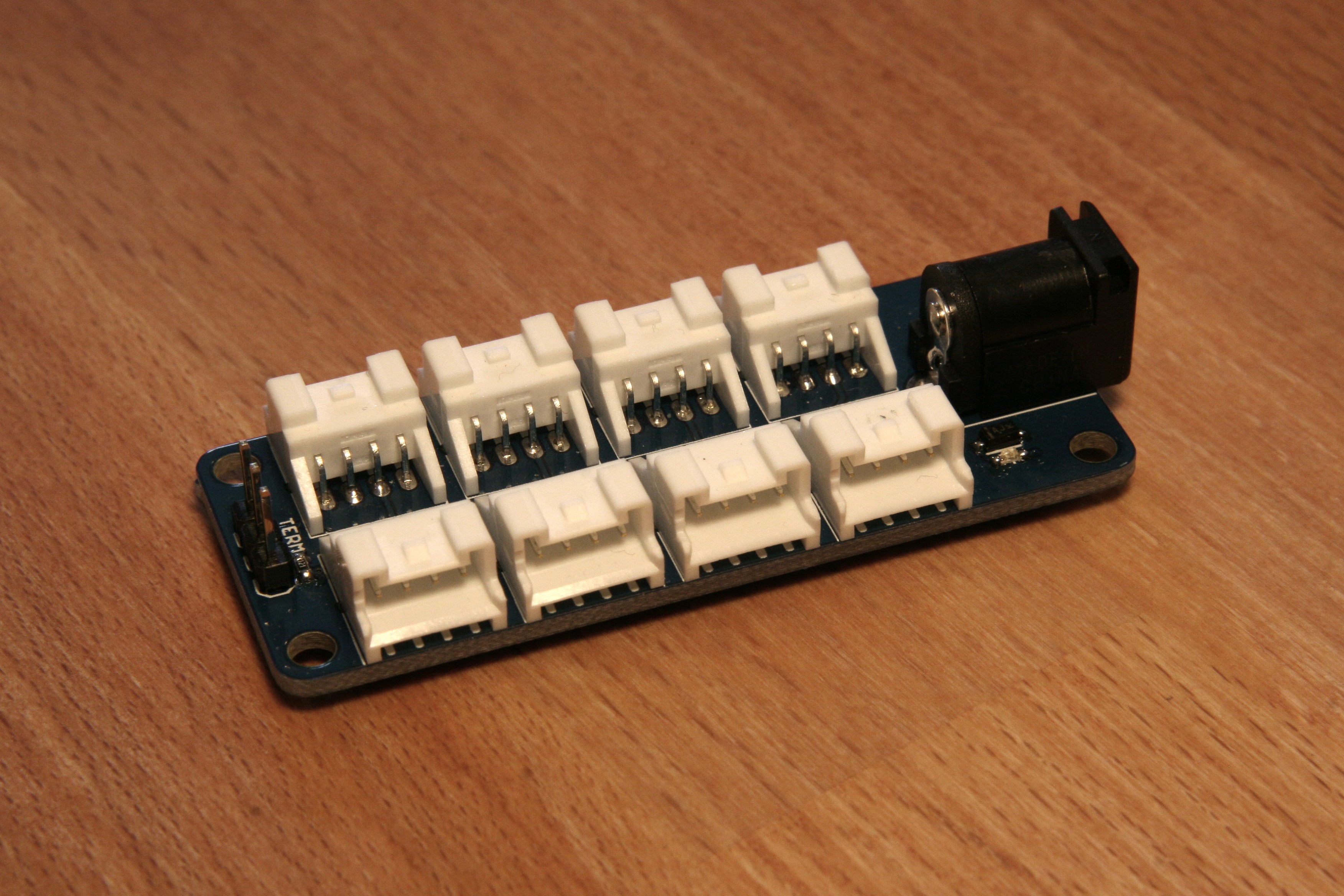
HydroHub Features:![]() HydroHub is a HydroBot module designed to connect together HydroBot modules in a star topology. The hub provides power and CAN connectivity to a total of eight channels. It has a DC barrel jack for connecting an external power supply, as well as selectable termination for the CAN bus.
HydroHub is a HydroBot module designed to connect together HydroBot modules in a star topology. The hub provides power and CAN connectivity to a total of eight channels. It has a DC barrel jack for connecting an external power supply, as well as selectable termination for the CAN bus.- 8 channels for connecting HydroBot modules
- 5.5mm DC barrel jack for power input
- 6-30V input works with 12V and 24V systems
- Selectable 120Ω CAN bus termination resistor
- Power indication LED
- JST-PA series connectors
- Open source design
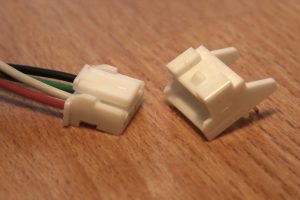
![JST-PA Series Connectors]()
This design introduces the switch to JST-PA series connectors for HydroBot modules. These connectors, although somewhat bigger and more expensive than the JST-ZH connectors used previously, will allow for lower gauge wiring and much higher currents than before. The new connectors support 22-28 gauge wiring and up to 3A per pin. All new module designs going forward will use JST-PA connectors and existing modules will be updated as part of the next revision cycle. The first module that has been updated to include the new connectors is the AirSense module, which has also added a light sensing feature. Other HydroHub features to note include a constant current driver for the power indication LED to keep brightness consistent over the entire input voltage range, and a CAN bus termination resistor that can be selected using a simple jumper to accommodate the needs of various network topologies.
All source can be found in the HydroBot repository. The BOM and generated gerber files are also included for easy replication.
-
HydroBot: Switches and Relays
09/19/2016 at 20:17 • 0 comments![]()
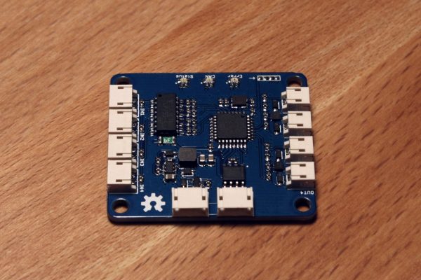
RelayDrive is a HydroBot module designed to drive relays and other electro-mechanical devices. It consists of 4 low-side outputs, each rated for 1A continuous current, as well as 4 digital inputs, and is controlled over CAN. This module is intended to drive mechanical relays, solid state relays, and solenoids for controlling devices such as lights, pumps, heaters, fans, and valves in a HydroBot hydroponic system.
RelayDrive Features:
- STM32F0 microcontroller
- 4 low-side 1A outputs
- 4 opto-isolated digital inputs
- 3 LEDs to indicate device status
- 6-30V input works with 12V and 24V systems
- JST-ZH series connectors
- Parallel bus connections for daisy-chaining
- Protofusion pogo programming interface
- Open source design
Each of the outputs of the RelayDrive module can be controlled as discrete on/off switches, or can be configured as PWM outputs. Each of the inputs can also be independently configured as digital inputs or frequency inputs. Frequency inputs are measured in Hz and can currently read input signals up to 1KHz. The default firmware uses a CAN baud rate of 500K. It sends out status messages on ID 0x204, with digital or frequency input readings, and receives command messages on 0x203 to control outputs and set input and output configuration.
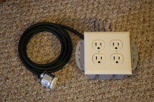
![IMG_2503]()
Because many devices in a hydroponic system run on mains power and require relays for control, I packaged up 4 solid state relays in a 2 gang electrical box. This keeps all the relays together without exposing any hot wires, and the 4 controlled outlets match up nicely with a single RelayDrive module.
All source can be found in the HydroBot repository, including firmware source code and hardware files. The BOM and generated gerber files are also included for easy replication.
-
Measuring Atmospheric Conditions
07/16/2016 at 17:02 • 0 comments![]()
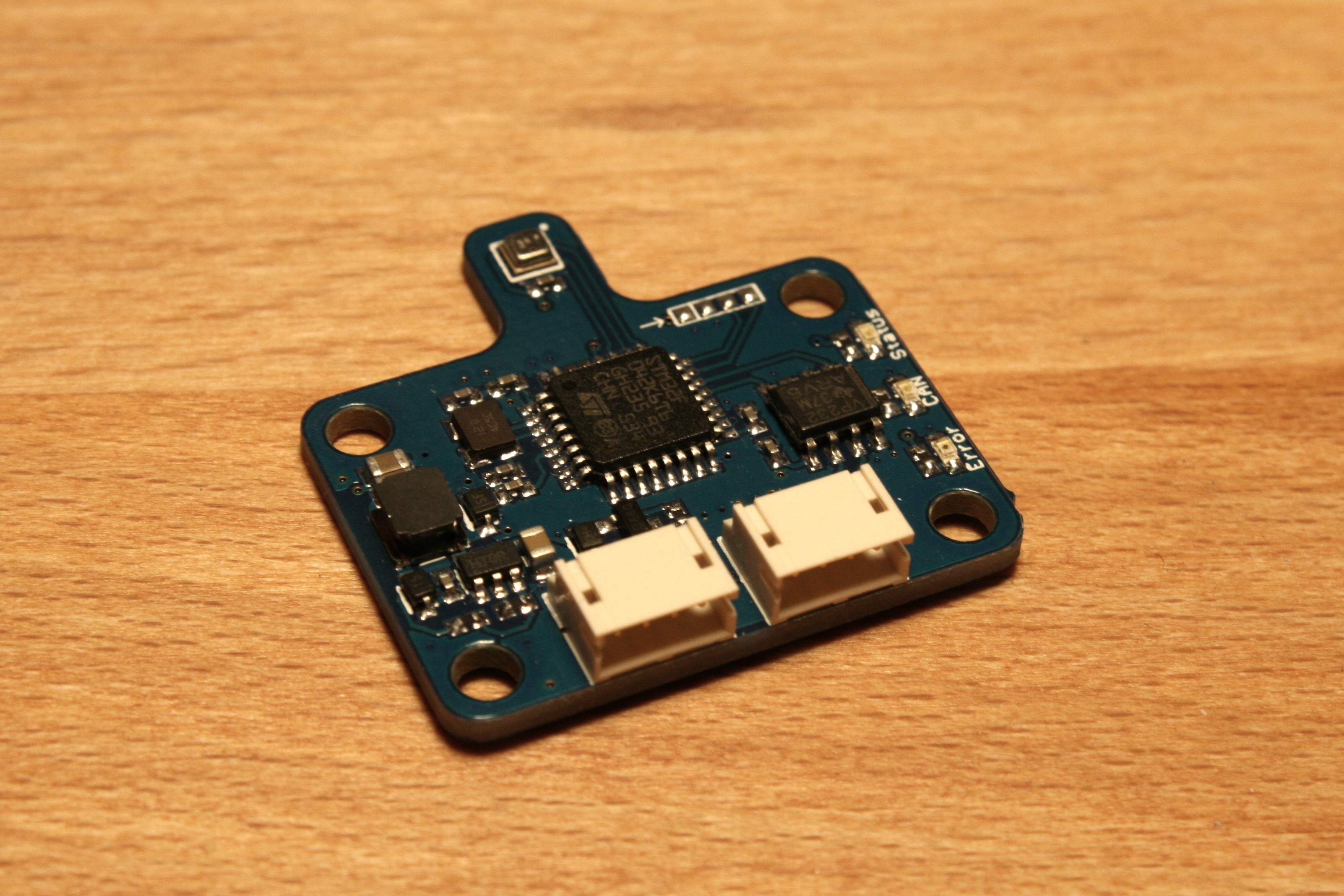
AirSense is a HydroBot module designed to measure air temperature, relative humidity, and barometric pressure. It uses the Bosch BME280 atmospheric sensor to take measurements and sends the results out over CAN. The module can measure temperatures from 0 to +65°C with ±1°C accuracy, humidity from 0 to 100% with ±3% accuracy, and pressure from 300 to 1100 hPa with ±1 hPa accuracy. Three LEDs indicate device status, CAN activity, and error states.
AirSense Features:- STM32F0 microcontroller
- Bosch BME280 atmospheric sensor
- 6-30V input works with 12V and 24V systems
- JST-ZH series connectors
- Parallel bus connections for daisy-chaining
- Protofusion pogo programming interface
- Open source design
The default firmware uses a CAN baud rate of 500K and sends out messages on ID 0x201. Temperature is recorded with 0.01°C resolution, and is sent in bytes 3 and 4 of the CAN message data. Humidity is recorded with 0.01% resolution and is sent in bytes 5 and 6. Pressure is recorded with 0.1 hPa resolution and sent in bytes 7 and 8. By default, sensors readings are taken every 100ms, and a message containing averaged measurement data is sent out once every second. Future firmware work will add module configuration over CAN with settings including CAN baud rate, CAN id, data frequency, sensor calibration, and more.
All source can be found in the HydroBot repository, including firmware source code and hardware files. The BOM and generated gerber files are also included for easy replication.
HydroBot
HydroBot is a modular control system for automating hydroponic gardens.
 HydroHub is a