Close
0%
0%

Sous-Vide, Adapt or Die Trying

A low-cost, circulating sous-vide system that uses novel COTS components.

Similar projects worth following
Yet another take on the DIY sous-vide cooker.

Come watch as I built a low-cost & simple sous-vide system, complete with water circulation, from inexpensive pet-store parts.

My first prototype, using a slow-cooker, wasn't working so well. So, I adapted, and, with a spark of inspiration, I went to the local pet-shop, and came back with some parts...

So, what makes a sous-vide system?

  • First, of course, you need a container; just about any will do.
  • Second, some water.
  • Third, you need a source of heat.
  • Fourth, a way to tell how hot your water is.
  • Fifth, a controller for your heat source.
  • ...and, optionally, sixth, a way to circulate the water.

A random bucket meets the need for the first, my sink the second, a DS18B20 the fourth, and obviously a Arduino, or a Raspberry PI, for the fifth.

What about the third and the sixth? COTS water heaters for small volumes, and high temp pumps, don't exactly fall off the shelves.

Pet-store to the rescue!

  • For the third, an aquarium heater is just about perfect... you've just got to lobotomize the thermostat.
  • The sixth, that's a bit more tricky. However, if we look at the Wikipedia article on Airlift Pumps, we can see that a simple pump can be made, with no moving parts, if you have an air source. Cue, the aquarium bubbler pump! A bubbler pump is designed for long run times, doesn't cost much, and satisfies the need for an air source.

Now... to test....
  • 1 × PSSR/ZC Tail Phase-cutting AC waveform, aka dimming.
  • 1 × Arduino Nano, Clone (ebay) Control all the things.
  • 1 × DS18B20 Temp Sensor, Waterproof Hey, that might be hot!
  • 1 × Aquarium Air Pump Fish need air too!
  • 1 × Aquarium Air Stone Big bubbles are out, little bubbles are in.

View all 9 components

  • A thousand words

    Chris08/14/2016 at 18:59 0 comments

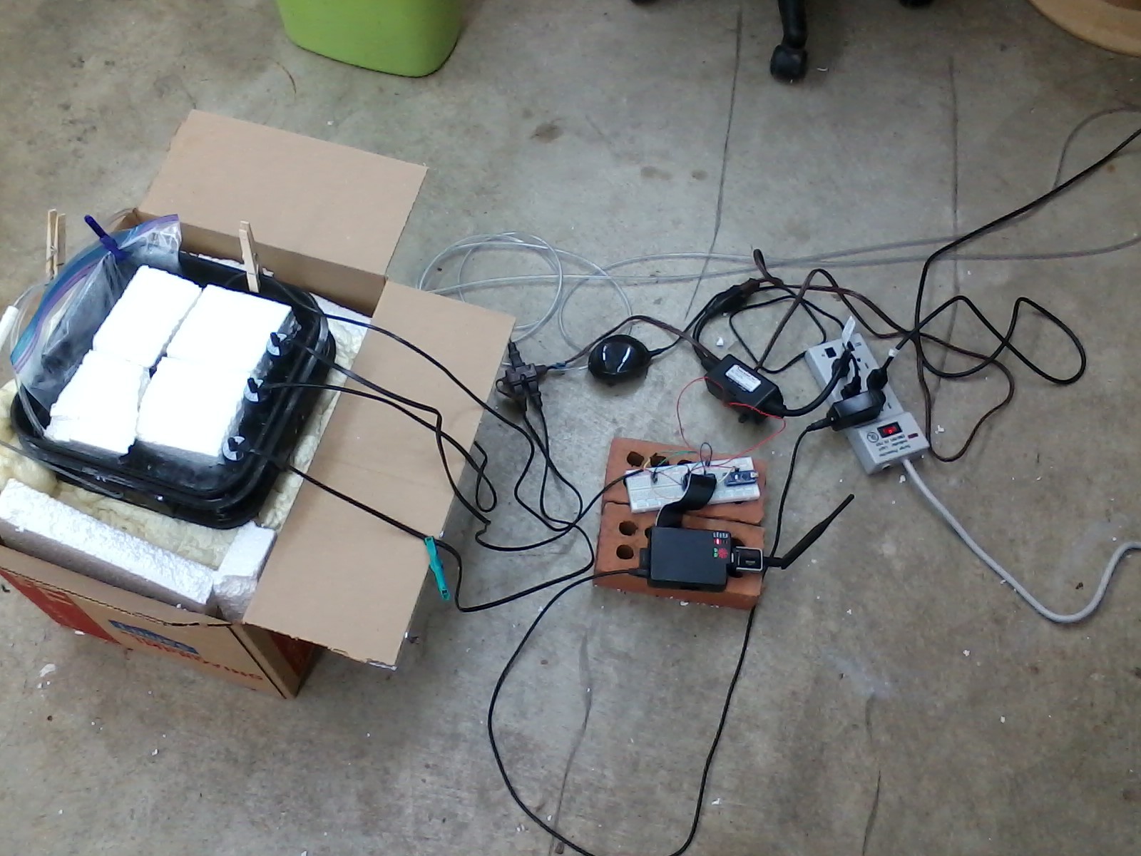
    Truly great projects involve lots of cords....

    What you see here is the "final" product, cooking away.

    The current water temperature is 167 Fahrenheit, and only deviates by roughly half a degree. I've got several chicken breasts cooking away in the plastic bag.

    The foam on top of the water is an attempt to limit evaporative losses and conserve some heat.

  • Performance

    Chris08/05/2016 at 18:34 0 comments

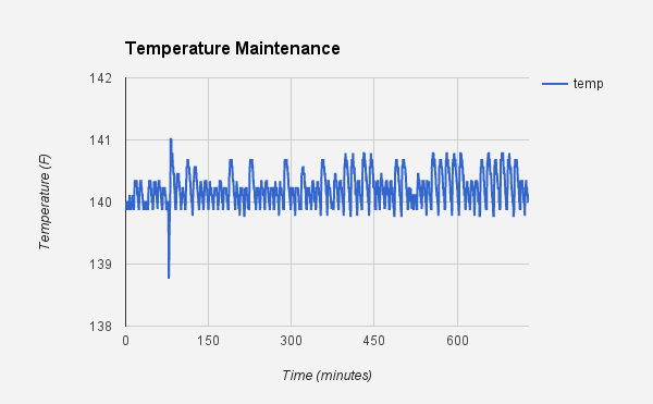
    Running the sous-vide system all night, the temperature was remarkably stable.

    As you can see in the above graph, the temperature stayed generally within +/- 1 degree Fahrenheit.

    The behavior was achieved using a simple monitoring loop. Every 30 seconds, I checked the temperature. If the current temp was below the set point (140) turn the heaters on, else off.

  • Try, try, try...

    Chris08/04/2016 at 23:38 0 comments

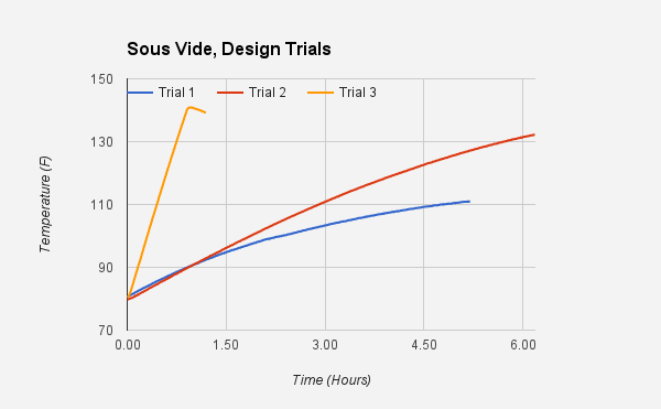
    After several iterations, I've come up with a very functional design. Let's look at some data and see what it took to get it right...

    ... third time's a charm!

    • Trial 1 was a 300W aquarium heater, in a 5 gallon bucket of water, sans insulation.
      • As you can see, the rate of heat gain wasn't that great, and thermal losses mounted, slowing gain down even more.
      • I gave up well before reaching the target temp (140 F).
    • Trial 2 was the same as Trial 1, with the addition of copious amounts of insulation (foam-in-a-can), side and bottom.
      • Again, heat gain wasn't all that fast, but the added insulation made a big difference in the heat loss.
    • Trial 3, now that's the ticket! I purchased 2 more 300W aquarium heaters ($8.00/per), for a total of 900 watts of heating.
      • The 5 gallon bucket heated to the target temperature (140 F) in roughly an hour.
      • After reaching target, my software shut down the heaters in order to measure the heat loss rate. Not too bad.
      • The PSSR/ZC tail isn't rated for 900W, only 450W, so I switched it out for a standard PowerSwitch Tail, which is rated to 15 amps.

  • Something's fishy!

    Chris07/29/2016 at 21:53 0 comments

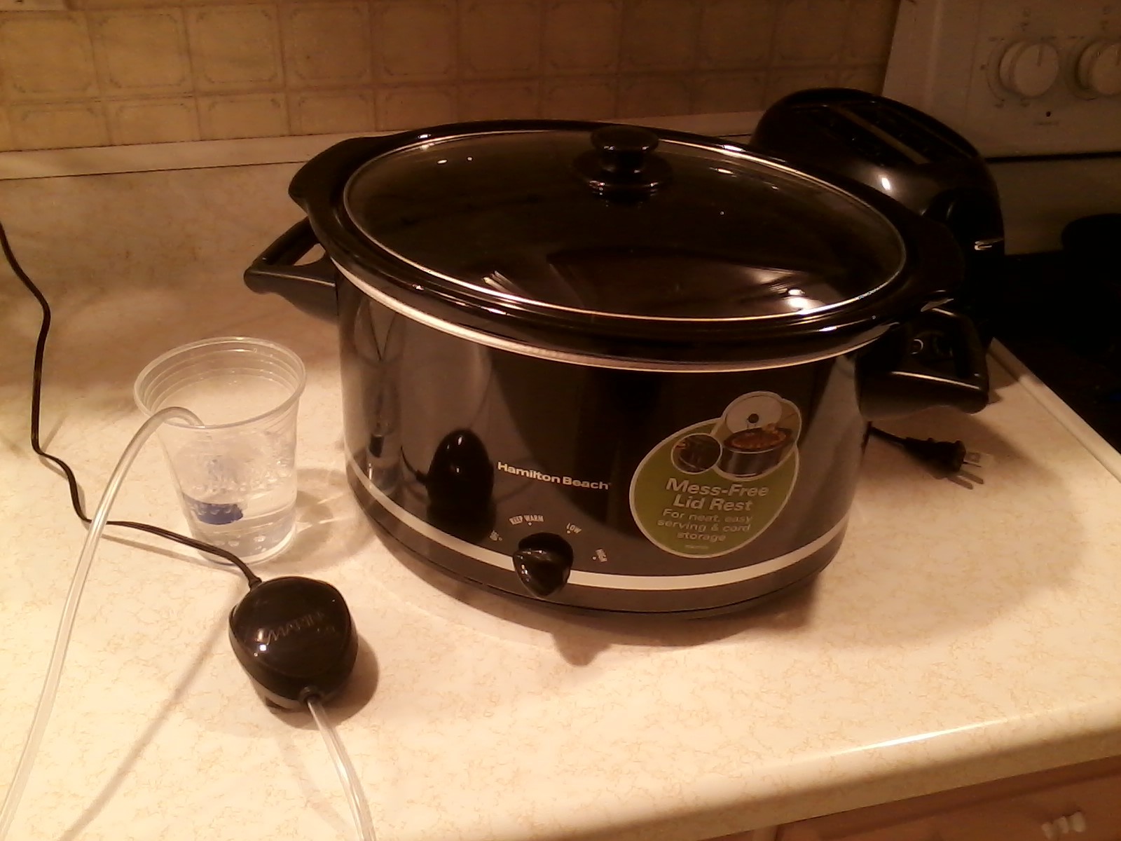
    The idea of using a slow-cooker as a sous-vide system is great! The implementation of using a slow-cooker as a sous-vide system, not so much.

    Slow-cookers have a lot of lag in the system; they take a long time to start, and stop, heating. The significant lag presents some substantial impediments to designing a control system, of any sort. While I'm not one to give up easily, I am one to be pragmatic and take a more simple approach when I see one...

    ...and thus, here we are.

    So, what do you get when you cross a lobotomized 300W fish-tank heater, an aquarium air-pump, an Arduino, a Raspberry PI, a PSSR/ZC Tail, and a little bit of code?

    You guessed it, a sous-vide miracle!

    I'll be back after the break with some pictures, data, and a verdict. (It takes a long time to heat up water!)

  • Plan Zero

    Chris07/15/2016 at 19:41 0 comments

    I've been thinking hard about how to implement a temperature controller, and I've come up with an initial plan.

    I'll plan on using the PSSR/ZC tail to control the heating level.

    First, I'll train a neural network to understand the relationship between power level and temperature so that given a temperature set-point as input, the network will output the appropriate power level to use.

    Second, I'll determine, experimentally, the maximum time it takes for the temperature to stop increasing after cutting power. Let's call this time (MT)

    To reach a certain temperature set-point, I'll apply full power and continually estimate the remaining time until the set-point is reached (RT). When RT - MT reaches zero, I'll cut power and monitor the rate of change in temperature. One the slope of the rate of change of temperature reaches some number (0.5?) I'll set the power level to the appropriate amount for the goal temperature. This should cause the temperature gain rate to level off more slowly, and reach zero when it gets to the goal temperature.

    It's a plan... having gone through some literature on working with temperature controllers in systems with delay, I've come to the conclusion that the problem of control, regardless of implementation, is extremely complex. For now, I'd like to get something working, even if it isn't perfect.

  • Failed Prototypes

    Chris07/11/2016 at 23:29 0 comments

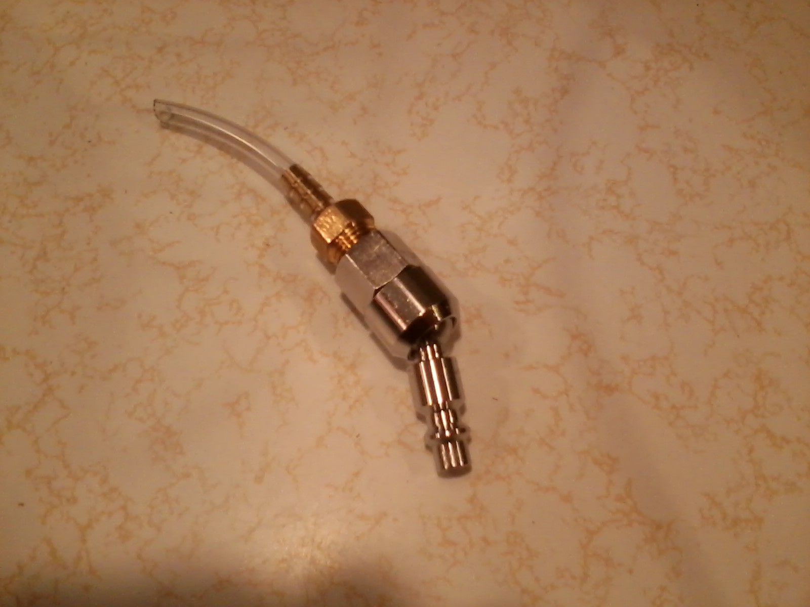
    Rather than start off with an aquarium air-pump, I tried using an air-compressor that I already had in my garage. I build an adapter to go from compressor fitting to hose to air-stone, and found that the output volume from the compressor was, as expected, perfectly adequate.


    The downfall was that my compressor is small; despite the high-pressure, the low-volume storage meant that the compressor wound up cycling often.

    An aquarium air-pump, while having a much lower possible output pressure, more than makes up in volumetric output, convenience, and noise.


  • Always Step Back

    Chris07/11/2016 at 23:17 0 comments

    Another thing to consider with any project is premature optimization and over-engineering. The use of phase-cutting for heat output control may, very likely, be overkill for a big vat of water and a ~300-watt heater (slow to change temp up, or down). A relay rated for 15 amps, running at most with 3, aught to have a very long lifetime, even at a relatively high rate of switching.

    Either way, it'll be interesting to see how each approach compares. For the loser, to the next project the parts will go!

  • Research, Considerations, Adjustments

    Chris07/11/2016 at 22:51 0 comments

    Today, I did a bit of research on neural network based temperature controllers, and found this article, which describes the design and training of a neural network for controlling a lab water bath. A critical feature of the network described within is that it doesn't output just a binary on/off, but instead a more linear power level.

    There are a lot of potential drawbacks to implementing a design that's only on/off. While it may initially seem like rapid on-off would be a perfectly fine PWM method to control heat production, it's really only a fine method if you're using solid-state components. With a mechanical relay, you're going to be in for a lot of noise, and shortened relay lifespan, if you attempt to control PWM with a high frequency. Depending on the cookware you're working with, a very-low frequency PWM behavior may be fine, but really only if there isn't a lot heat loss and the heating element is lower powered (thus you can create a slow sin-wave sort of temperature fluctuation around the set point and avoid relay switching too often).

    Given the drawbacks, I decided to look into a more appropriate hardware implementation. Looking at the PowerSwitch Tail product site, I noticed the PSSR/ZC Tail, which combines a solid state relay and zero-crossing detection into one product.

    Perfect!

    One problem though, the PSSR/ZC Tail is only rated to 450 watts. So, with an ammeter in hand, I hooked up an 8-quart slow-cooker, and discovered that it uses 1.03, 1.94, and 3.0 amps at keep-warm, low, and high settings. This translates to roughly 118, 223, and 345 watts, respectively. The wattage is within the range for the PSSR/ZC Tail.

    Given what I've learned, and the drawbacks to binary operation, I'll be changing my approach to us a neural network directly to determine a power output level on a linear scale.

View all 8 project logs

Enjoy this project?

Share

Discussions

cgearlab wrote 07/13/2022 at 15:40 point

this is really amazing project . i am also working on a   cooking gear lab page.

  Are you sure? yes | no

m005kennedy wrote 08/24/2016 at 01:32 point

nice!

  Are you sure? yes | no

Similar Projects

Does this project spark your interest?

Become a member to follow this project and never miss any updates