-
2 more days to place a bid on Ebay
09/27/2017 at 06:43 • 0 comments -
SPINO IS FOR SALE. ONLY 100USD!
09/20/2017 at 06:25 • 0 commentsWe are selling all our prototypes and spare parts.
Starting price: 100usd on Ebay.
Just the 10 teensy 3.2 you'll get are worth 200usd.
-
SPINO is going Open Source!
02/09/2017 at 02:09 • 0 commentsWe've decided to postpone our Kickstarter campaign and to go Open Source.
You want to help us improve our hardware design? develop some apps for Spino? or just get a prototype to play around with? contact us! spino.display@gmail.com
Don't forget to check out this video of our latest software development (code source available on www.spino.tech)
More information about the open source project available here:
http://www.spino.tech/open-source
-
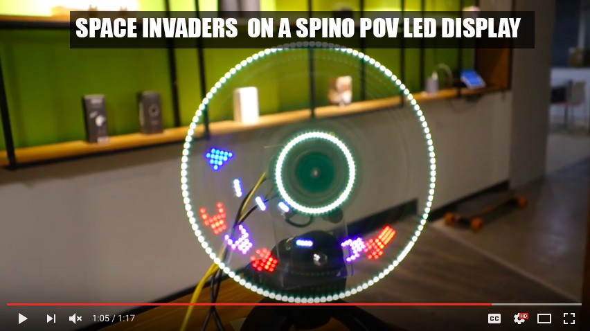
Space Invaders on a Spino POV LED display
09/26/2016 at 07:32 • 0 comments
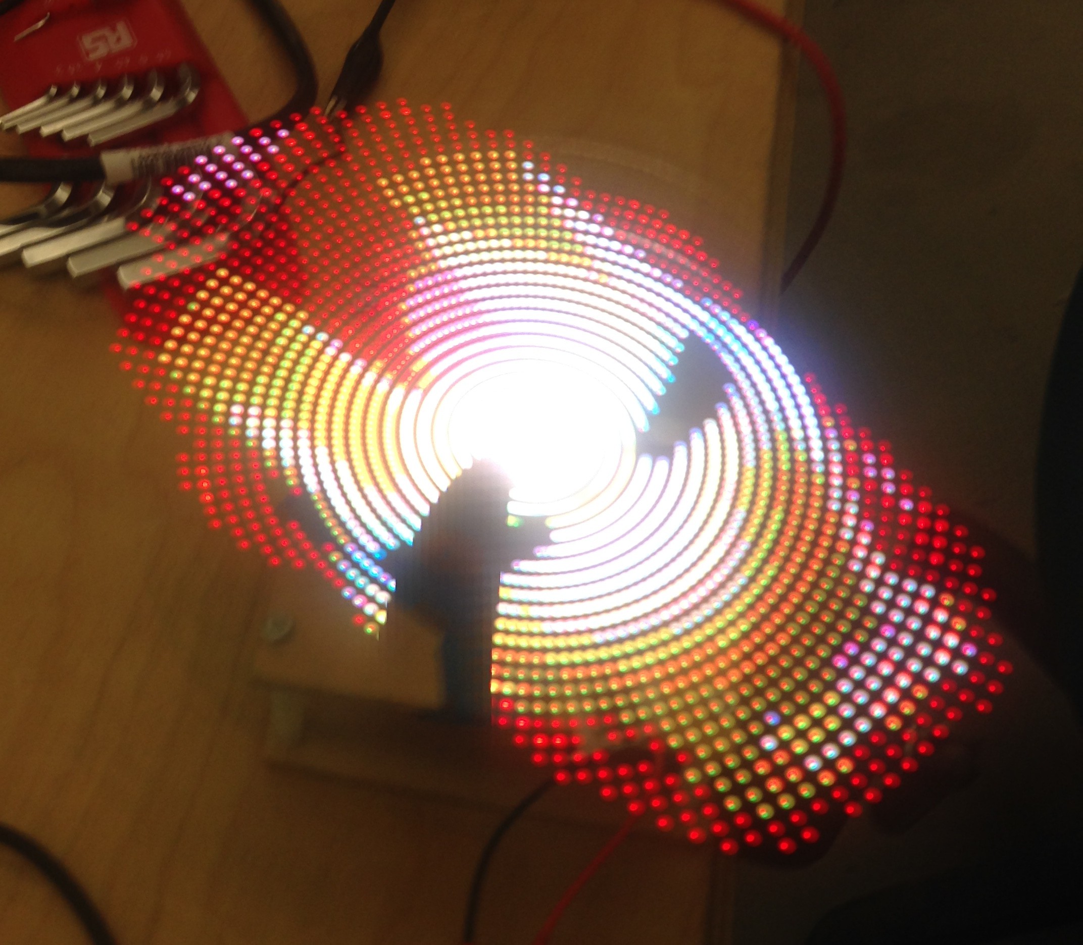
In this video we are testing a simple demo of space invader on Spino. As you can see the display is spherical which requires to adapt the game accordingly. Instead of using cartesian coordinates we are are using polar coordinates. The pixels, Instead of being arranged along a grid like in a normal display are arranged along concentric circles. This makes designing games much more challenging.
In this case, the test shows us that a shoot them up game is not a good fit for the display as shooting ennemies along circles is a bit awkward. We will modify this game so that the little space shuttle can go all around the circle while having to avoid obstacles which will be much more fun!Spino is a connected POV LED display. All the data is streamed from a computer to the display through bluetooth. In the final version of the product we will use a smartphone instead of the computer. The smartphone will run the games and will also be used as a controller.
-
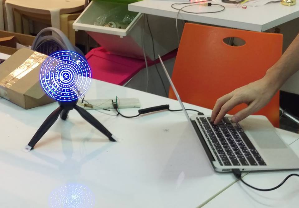
Connected POV LED display: final video
09/19/2016 at 14:36 • 0 comments
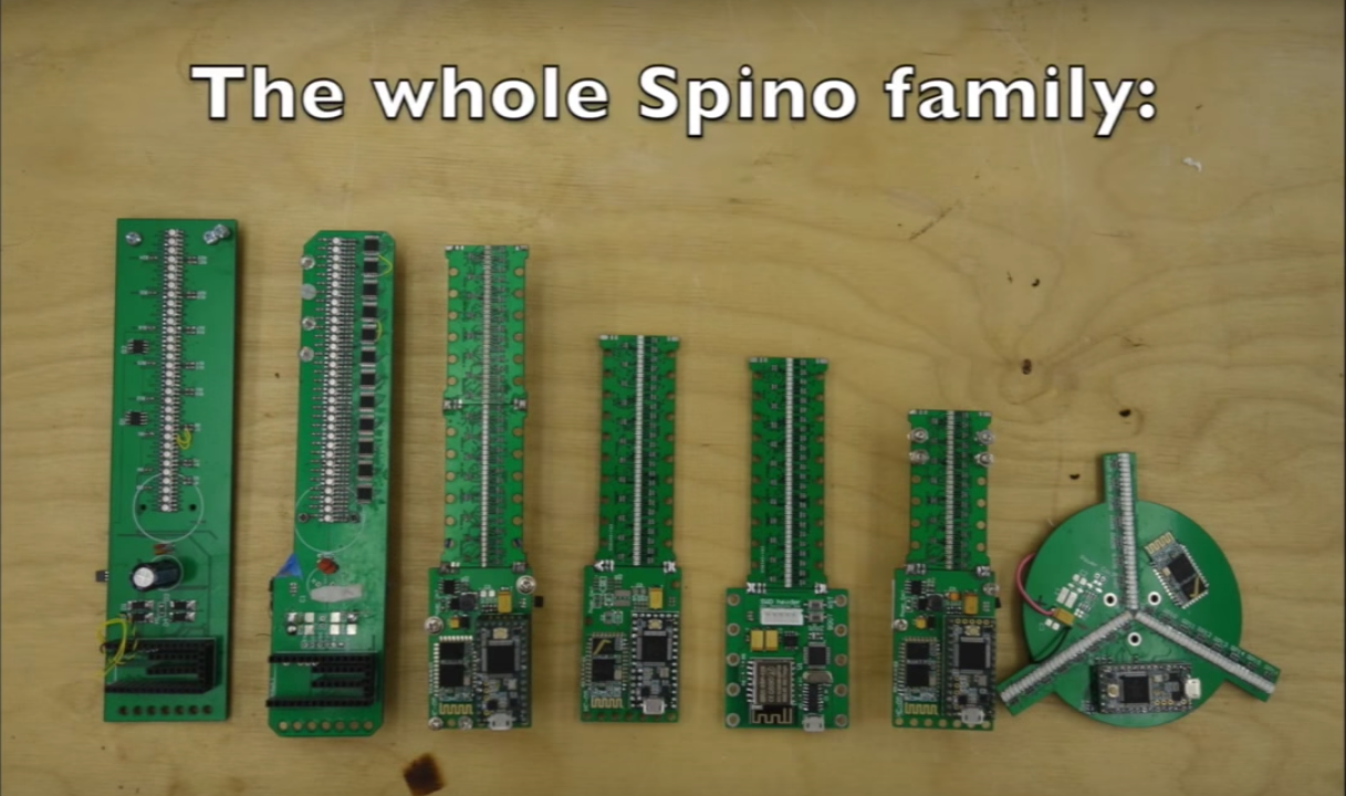
After 6 PCB iterations, we have finally reached a sufficient level to shoot this little video (see below)All the data is streamed thought bluetooth from a PC to the display (reaching the right level of compression has been a challenge and we are still considering using WIFI instead of BT)
What you'll find in the video:
- more info about the PCBs
- a few demos of retro games on ouf POV LED screen (some are real games that you can actually play others are just videos that we have ported to the display)
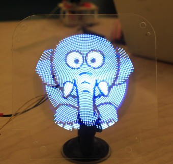
- demos of what we call "holographic animations" (it's just a matter of finding videos that look ok on our display (resolution, colors...), If possible with a black background that will actually be displayed as transparent in the end)
- And a short demo of live streaming from a webcam that we already posted here some time ago
Please feel free to make comments, to tell us how you would like to use this display for and what features you want us to add next.
If you can code in Python and would like to develop some small games or anything else for this display, please contact us.
-
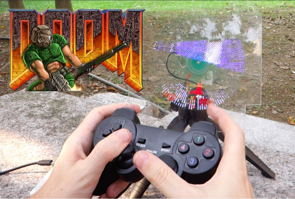
Hacking Doom code for Spino transparent LED POV display
09/03/2016 at 10:02 • 2 comments
Doom (the original version), is not only one of the best game ever made, but it's also a great example of C code.
Thanks to id Software decision to release the code as open source in 1999, anybody can have a look and modify it.
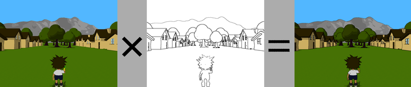
I had this project of changing the rendering of doom, to add a border effect to the walls, or cel shading. You can check the video at the end of this post to see why I wanted to do this to start with.
This idea of the cel shading algorithm (as described in the Wikipedia page ) is simple: we apply a Sobel filter to both the depth and normal buffers of the rendered frame, that we then superpose to the colors.
(Image from wikipedia)
I used the excellent chocolate-doom port of Doom, since this is the closest to the original I could find, and it compiles nicely.
My goal is to create my own buffers for depth and normals, and hook a function to fill them inside the rendering code, then just before the final blit, to call an other function to perform the Sobel filter and applying to the final image.
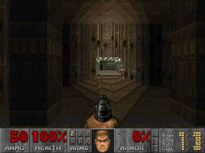
Here is what it will looks like:
-- Before. --
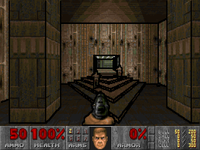
-- After. --
The difficulty when looking at doom source is that most of the functions have side effects modifying global variables. I have to admit it is a bit ugly, and I suspect that this was an optimization to avoid useless copies into the stack.
Neither the less, the code is easy to follow, as there is almost no abstractions and indirections. Clearly, John Carmack is an adept of the New Jersey style of programming.
I came up with this simplified function call tree for the rendering algorithm:
R_RenderBSPNode
    R_Subsector // For each visible subsector
        R_FindPlane
        R_AddSprites  // Fill the vissprites list
        R_AddLine     // For each wall (front to back)
            R_ClipSolidWallSegment
                R_StoreWallRange(start, stop)
                    R_CheckPlane
                    R_RenderSegLoop
                        R_DrawColumn    // What I am looking for
R_DrawPlanes  // Render ceiling and floor.
R_DrawMasked
What they call 'line' is really a wall surface. The reason it is a 'line' is because from a logical point of view, doom walls are just 2d lines extruded vertically (they never have slopes).
As we would expect, the walls are rendered front to back (function
R_AddLine). To prevent rendering on top of previous walls, the code keeps an array of up to 32 ranges (struct cliprange) of already rendered walls. Since the front to back order is guarantied, there is no need for an actual depth buffer.In my case, what I am looking for is the function
R_DrawColumn, that ultimately renders a column of pixels from a sprite. It is used for both the walls and the sprites.Before the function is called, some global variables are set:
dc_x:            x position.
dc_yl:           Start y position.
dc_yh:           End y position.
dc_iscale:       Texture scale (i.e: view distance).
rw_normalangle:  Normal of the surface angle.
Those are all I need to maintain the depth and a normal buffers. In
R_DrawColum, I add a call to my own functionspoom_AddColumn, that fills some pre-allocated buffers:void spoom_AddColumn(int x, int y1, int y2, int z, int a) { double angle = M_PI * a / ANG180; int y; for (y = y1; y < y2; y++) { depthBuffer[y * WIDTH + x] = (double)z / ((uint64_t)1 << 16); normBuffer[0][y * WIDTH + x] = cos(angle); normBuffer[1][y * WIDTH + x] = sin(angle); } }(Note that at the time when doom was release, such unoptimized code would kill the performances of the game. Fortunately this is of no concern for my needs).
Now that my buffers are filled, I just need to process them with a Sobel filter at each frame, and use the result to add the borders on top of the color buffer. I do it in a single function:
// Screen point to the color buffer.
void spoom_Apply(byte *screen)
{
    int i, k;
    gaussianBlur(depthBuffer, tmpBuffers[0]);
    sobel(depthBuffer, tmpBuffers);
    gaussianBlur(normBuffer[0], tmpBuffers[0]);
    sobel(normBuffer[0], tmpBuffers);
    gaussianBlur(normBuffer[1], tmpBuffers[0]);
    sobel(normBuffer[1], tmpBuffers);
    for (i = 0; i < WIDTH * HEIGHT; i++) {
        if (    depthBuffer[i] > 1.0 ||
                normBuffer[0][i] > 0.5 ||
                normBuffer[1][i] > 0.5) {
            screen[i] = 0;
        }
    }
}
The Sobel and Gaussian filters are implemented with a convolution product:
static void convolve(const double *m, const double *kern, double *dst)
{
    int i, j, i2, j2;
    double v;
    for (i = 1; i < HEIGHT - 1; i++)
    for (j = 1; j < WIDTH - 1; j++) {
        v = 0;
        for (i2 = -1; i2 <= 1; i2++)
        for (j2 = -1; j2 <= 1; j2++) {
            v += m[(i + i2) * WIDTH + j + j2] * kern[(i2 + 1) * 3 + j2 + 1];
        }
        dst[i * WIDTH + j] = v;
    }
}
static void gaussianBlur(double *m, double *tmp)
{
    const double kern[] = {
        1. / 16, 1. / 8, 1. / 16,
        1. /  8, 1. / 4, 1. / 8,
        1. / 16, 1. / 8, 1. / 16,
    };
    convolve(m, kern, tmp);
    convolve(tmp, kern, m);
}
static void sobel(double *m, double *tmp[2])
{
    int i;
    const double kernx[] = {-1. / 1,  0. / 1,  1. / 1,
                            -2. / 1,  0. / 1,  2. / 1,
                            -1. / 1,  0. / 1,  1. / 1};
    const double kerny[] = {-1. / 1, -2. / 1, -1. / 1,
                             0. / 1,  0. / 1,  0. / 1,
                             1. / 1,  2. / 1,  1. / 1};
    convolve(m, kernx, tmp[0]);
    convolve(m, kerny, tmp[1]);
    for (i = 0; i < WIDTH * HEIGHT; i++)
        m[i] = sqrt(tmp[0][i] * tmp[0][i] + tmp[1][i] * tmp[1][i]);
}
Finally, here is the final result, of me playing doom on a LED POV display. The walls are much easier to see compared to the unmodified game.
By the way, me and a friend are working on this project (link: http://www.spino.tech), feel free to ask us any question about it.
-
Week 2 & 3: smaller LEDs, webcam streaming
08/23/2016 at 05:32 • 0 commentsWe made some change for the second prototype:
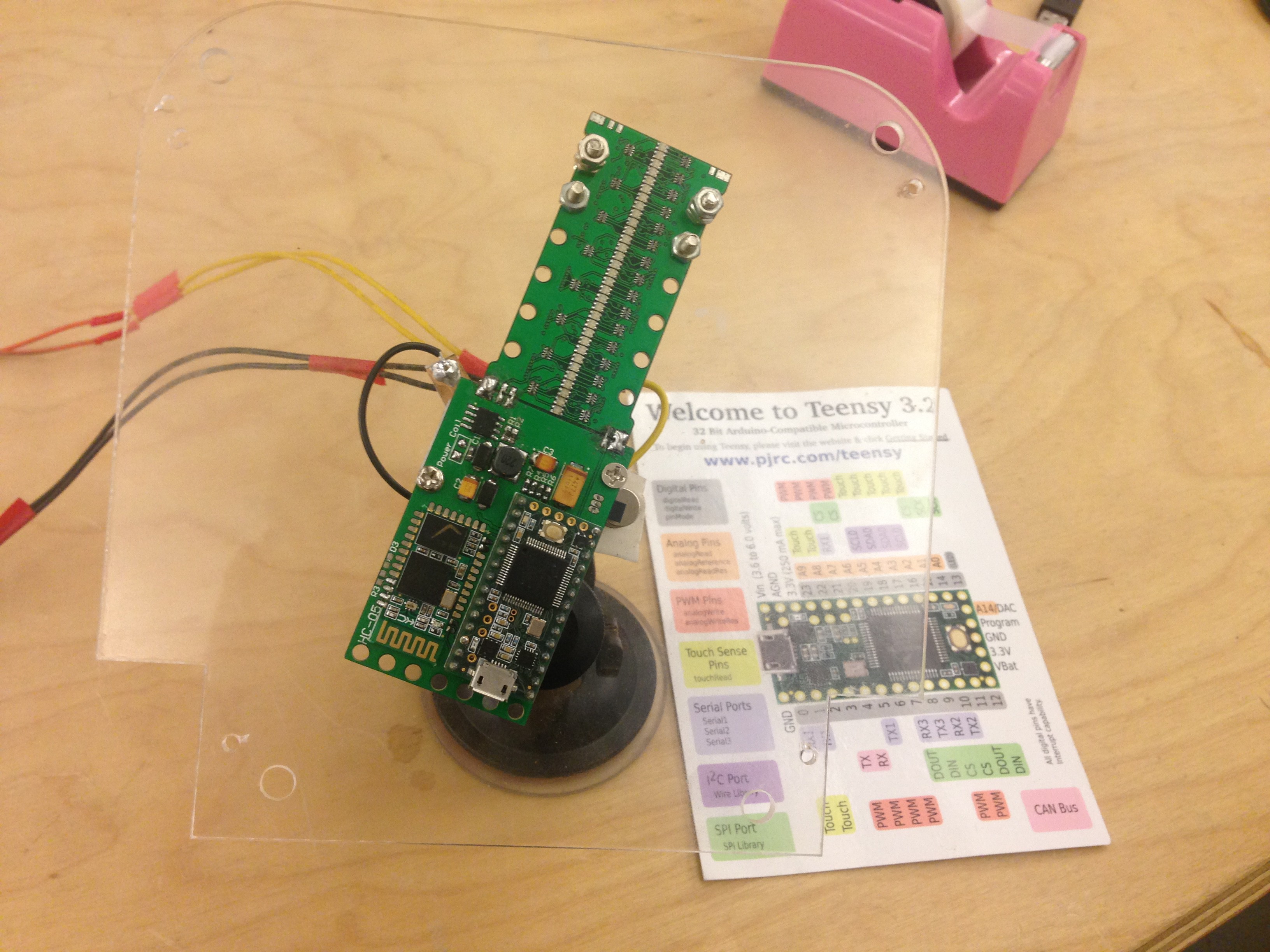
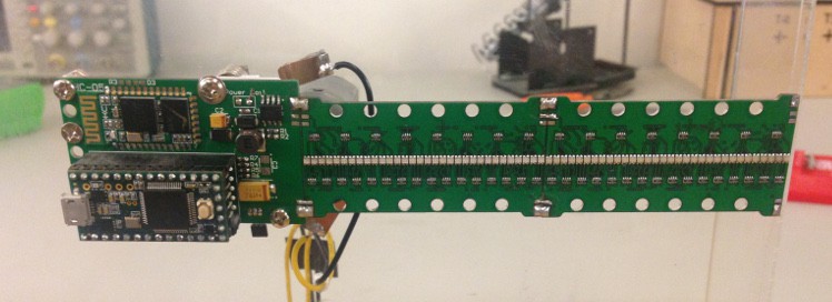
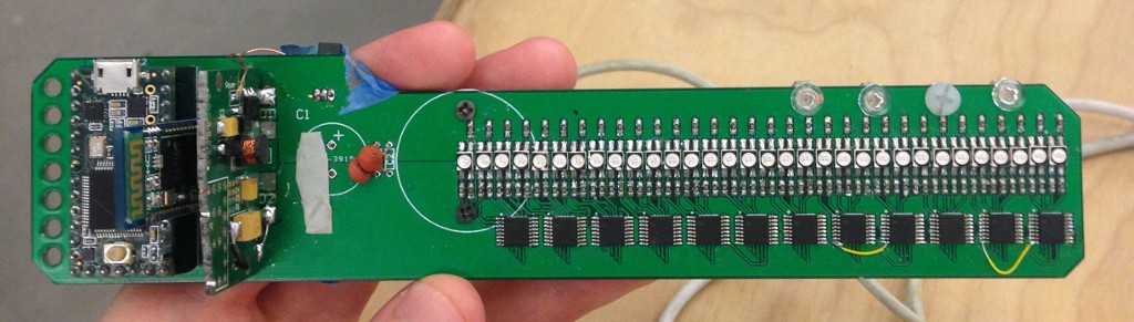
- We separated the PCB into two parts: one for the central part with the teensy and HC-05 bluetooth module, and one for the LEDs array.
The LEDs PCBs can be soldered to each other to double the number of LEDs, so that we can test both 32 and 64 LEDs prototypes. - The power transmission is now using brushes instead of coils. We hopped that this would fix some troubles we had with the hall sensor not getting enough power, alas, the problem still persists.
- We switched to even smaller LEDs. The SMD 0603 RGB. Probably as small as we can get. This increases the density of the the image.
Some pictures of the new design:
32 LEDs.
64 Leds, by concatenating two 32 LEDs blades together.
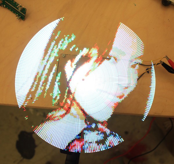
For a funny demonstration of the display capacities. We made a software that
can streams a webcam video in real time into the display:And some rendered images:
Don't hesitate to contact us if you have any question. - We separated the PCB into two parts: one for the central part with the teensy and HC-05 bluetooth module, and one for the LEDs array.
-
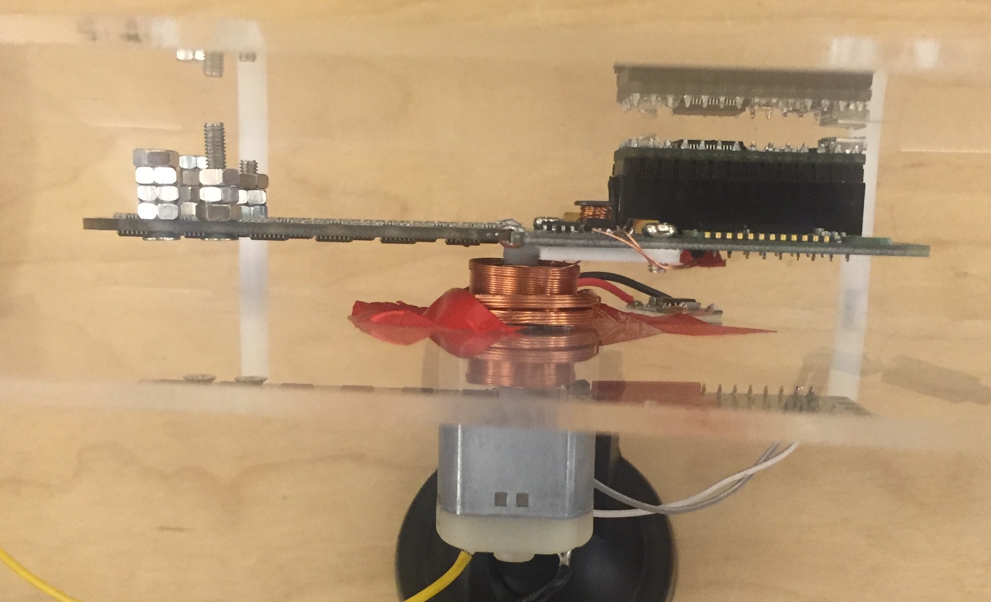
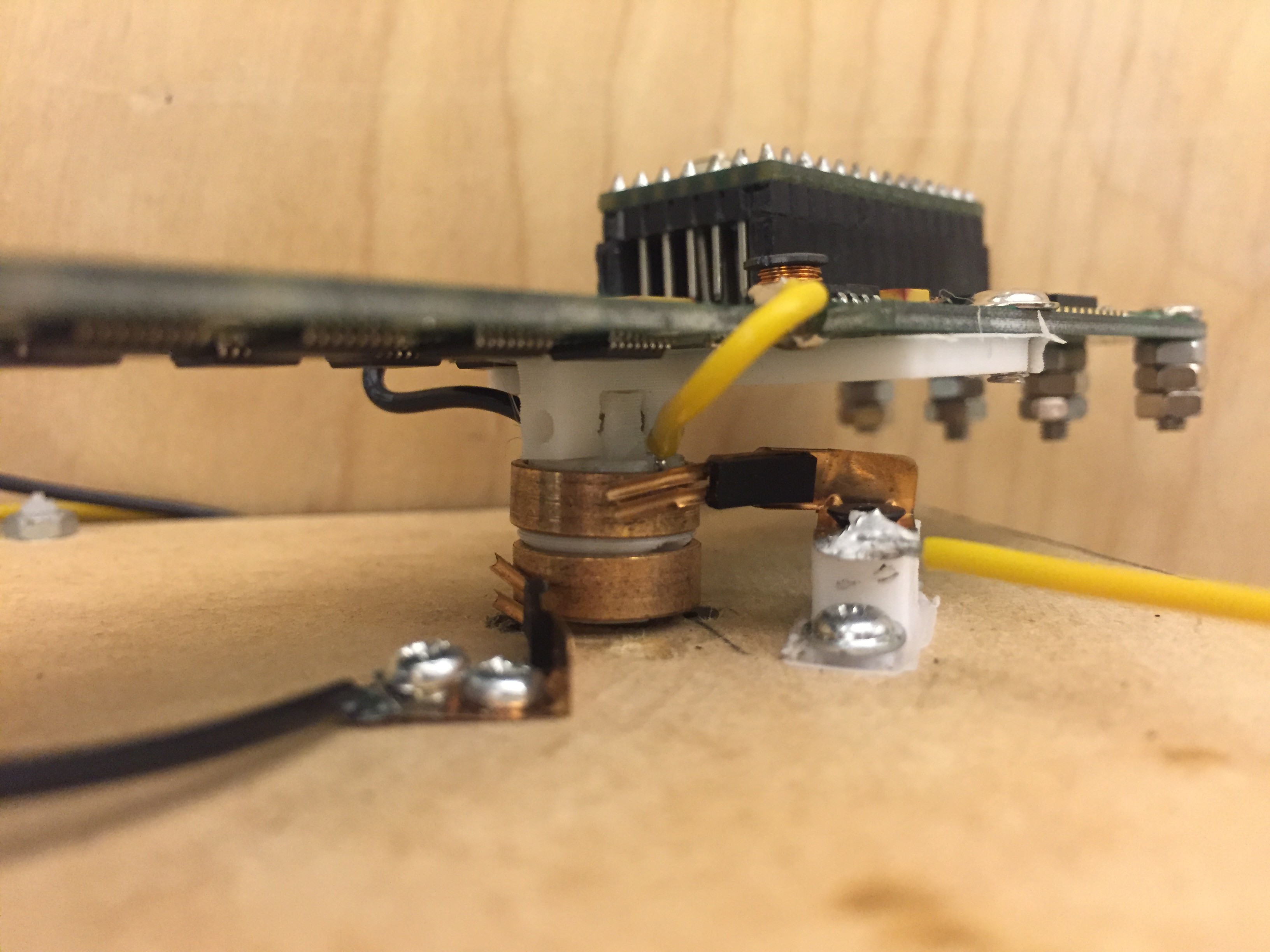
Sending power through the rotating shaft
08/15/2016 at 06:22 • 0 commentsFollowing a question in the comments, here is more information about how we managed to connect the PCB to the power supply (the data being directly sent by bluetooth)
We first started with electromagnetic coils as it's a contactless solution. But we faced some issues: the hall sensor did not get enough power to work properly (the LEDs were ok though).
We ended up going for brushes; which solved the power problem and enabled us to remove some elements from the PCV (AC / DC converter)
ELECTROMAGNETC COILS
We transmit power by the wireless charging module, so for the receiver we use the IC recommended for this module: T3168.
We use the diode in the first part to change AC to high voltage DC, and use IC to control this buck converter to hold the voltage of output.BRUSHES (hand made...)
-
Second week, bluetooth streaming, with a little game.
08/10/2016 at 08:15 • 0 commentsOur first prototype was a relative success, but the size of the PCB was too big, and we want to eventually put more LEDs in the display.
For the second iteration we use twelve 74HC595 shift registers to drive the thirty-two RGB LEDs. The PCB arrived from China after a week. There was a minor error in the design, easily fixed by soldering two jumps.On the left side, we can see the teensy, HC-05 bluetooth modue, and AC/DC converter for the power.
We also started to work on the bluetooth streaming. The idea is to use the display like a screen. It makes for an interesting challenge since the data need to be compressed enough for bluetooth low speed, and yet still need to be easily uncompressed on the teensy.
An other issue we faced was that propagation speed of the data along the shift registers limits the number of time we can blink the LEDs. After some time tweaking the software, we got it working properly.
And here we go for our glorious first video game test: