 Michael O'Brien
-
Quick Notes: Extruder resolution vs Z-Axis Resolution
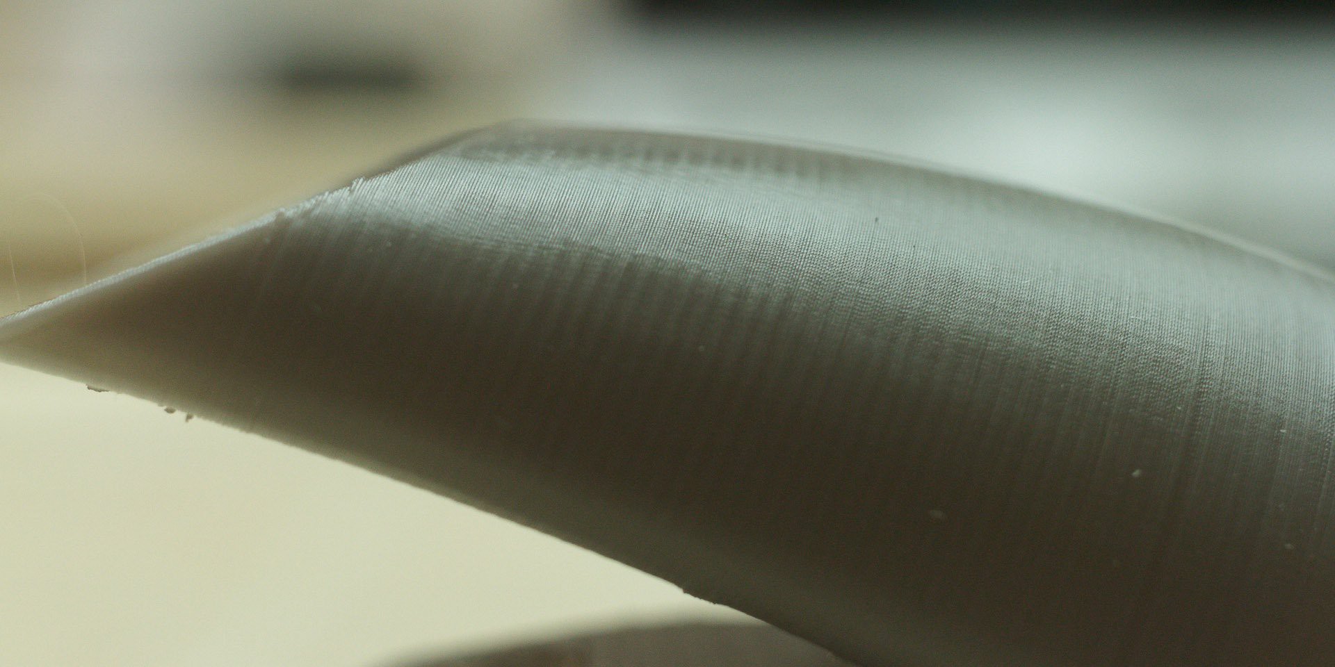
11/03/2016 at 08:42 • 1 commentIn one of the photos I posted, I have a ducted fan holder for the E3D V6 hotend. This was printed with a 0.6 mm nozzle and 0.1 mm layer height. If you've seen me on the Facebook group, you know I preach about using 0.04375 mm layer heights and this was before I figured that out. What happens if you increase layer resolution but you do not increase extruder resolution? An explanation after the break.
![]()
If you view the image full res, there is another detail aside from the aliasing banding. If you recall toys of old, and some new, you'll see a pattern on the layers that resembles what fake stitching looks like. Much like fabric threads on those old toys. This is caused by the momentary increase in flow & pressure as the extruder microsteps one tiny bit at a time. Let's quantify that.
The hobbled bolt has a minimum diameter of ~10.15 mm. This give us a circumference of about 31.8872 mm, aka that amount of travel in 1 revolution. This equates to just over 100 steps/ mm, to which I have my Mini calibrated to 101.6 steps/mm, so all is good. So, in 1 microstep @ 1/16th microstepping of a 200 step motor, how much filament gets pushed out of the nozzle? Almost 85 microns:
![]()
From the resolution shown in the photo, I can say that doubling the frequency of the "stitching" would nearly hide it, but quadrupling it will eliminate it. Thankfully, this driver can easily do 1/64th microstepping if you cut the correct trace. This gives you a length of ~21 microns:
![]()
If we're lowering our layer height to 43.75% of that print, we'll need to double our microstepping to keep a similarly smooth finish. Egads, we're at 1/128th microstepping!
Now, there is increasing interest over on the FB group for 20 micro layer height. In order to achieve this we need to swap out the drive gear to M5 or M6 rods and due to the slow travel, I'd advise the M6 x 1 mm rod. You should be able to push it at ~4-5 mm/s with 1/2 stepping. Anyhow I digress. If we go from a 43.75 micron height to 20 micron height, we have the same type decrease again. If we're going this small, then it's likely that we'll be using fine nozzles too, such as 0.25 mm. We'll probably want a 0.9˚ stepper too.
![]()
Granted, all of this is theoretical and doesn't account for post-processing such as flame brushing, acetone, or the like to clean up the surface. However, the finer you start with, the finer you finish with. If you do not tend to the extruder when you thin the layers, you're not gaining as much as you could.
-
Axis Resolution & Speed
10/09/2016 at 14:24 • 0 commentsI've mentioned before that the fastest I've measured from this board's microcontroller is ~38 kHz. With some math which I'll show later, this gives a theoretical speed of ~395 mm/s for the X, Y, and Z-axis steppers. However, stepper driver speed and torque is a much more complex issue than I even expected. Here is what I've learned so far and I want your help to point me which direction I should go.
PS: This is a *long* post
I recently edited 2 past logs because the stepper drivers *are not* HH4988's, but actually HR4988's. Their datasheet is available here, mirrored here. Unlike the A4988 that it's derived from, which microstepps at just 1/2, 1/4th, 1/8th, & 1/16th intervals, this driver uses all 3 bits and will do 1/32nd, 1/64th, & 1/128th microstepping on top of the others. Microstepping is one factor regarding speed and resolution.According to reprap.org's wiki, Marlin's limit on an 8-bit, 16 MHz micro is 40 kHz, which makes me believe that despite having a <facetious> glorious 32-bit microcontroller </facetious>, they aren't clocking it anywhere close to it's 72 MHz limit, but instead at ~16 MHz. I've measured a peak step rate of about 38.17 kHz. I plan on sniffing the power line to see if I can figure out a clock speed. If this assumption is true though, either hacking the firmware, overclocking by using a faster crystal, or getting Malyan to let us configure how fast the STM32 runs, we're stuck at a low steps-per-second rate.
I *hope* that we're running at 16 MHz and I hope that we can be given 64 MHz speed. Coupled with a a pulse rate of 3.33 us average, 3.75 us peak, we could get a step rate of ~133 kHz, or about 3.5x faster than the current top speed. Increasing the max step rate our micro wouldn't the limitation to speed or resolution. The is the second factor regarding speed and resolution.
Back to the HR4988. I need to do some more active probing of this chip while driving a motor, particularly because my current probe has a bandwidth of 20 kHz and the PWM current control has a clock rate of ~32 kHz when RSOC is shorted to ground. When dealing with the current control, the HR4988/A4988 doesn't have the ability for a straight up fast decay mode. This is partially why in prior captures, the current fails to escape the windings and we begin missing microsteps when we try and go faster than ~50 mm/s. However, if you put a pull-down resistor between RSOC & ground, you can change the frequency of the PWM current control, but this is caused by adjusting the off time of the logic. With reduced off time, faster speeds can only be achieved through hardware means: "braking diodes". These are factors 3 & 4 that affect speed and resolution.
But what about the motors? Ah the motors. Physics. Electromagnetic spectrum. Not trying to be pedantic, but high school and college physics are a handy thing to remember here. I'm assuming most are like me that if they see 2 motors rated at similar holding torque values and one is rated for 1.7 A and the other for 2 A, that the one w/ a 1.7 A rating is more "efficient". THIS IS WRONG. Have a read here and download StepperSim here.</end forward>
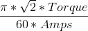
The problems with brushless motors is back electromotive force, aka "back EMF". This is the magnetically-induced voltage caused by the spinning motors. It causes 2 things to happen: electromagnatic braking and the inability to "drain" current as it is sloping towards 0. Back EMF can be estimated as a relation between holding toque and max current rating with the following equation:
![]()
Take this number and multiply it by how many RPMs your motor is revving to see what your estimated RMS, B-MEF voltage is. Long story short is that you want this as low as possible. You cannot decrease this voltage unless you spin the motor slower. You can overcome the effect of this voltage by increasing the drive voltage. Why? I'm not sure. You can dissipate the voltage with braking diodes too, but you have to pick the right ones.
The short of this is that you want a high amperage motor that has just enough torque to move your printer components at a desired RPM, thus speed. This is the 5th factor in motor speed and resolution.
The last thing to consider is much simpler and about the only other thing most people consider: how big is the pulley on the end of the motor? We have a 17-tooth pulleys, ones without concentric bores, all across the machine. With a MXL belt, which dictates a 0.08" tooth pitch, this gives us a 34.544 mm travel distance in 1 revolution of the motor. With our 1.8˚ stepper motor and 1/16th microstepping, we have an idealistic 10.795 micron resolution on X & Y axes and an error of +/- 86.36 microns. If we lower the tooth count, we increase resolution proportionally but decrease speed proportionally. Increase tooth count and the opposite happens. This is the final factor in speed and resolution.
Note: Even though the MXL belt is 2.032 mm per tooth, a GT2 belt is 2 mm per tooth. This is 1.6% error, which matters over the long run. However, on a 24 tooth pulley, about the largest that can fit on the Z-carriage, this will cause about a 9.6% difference in tooth pitch (think of is in quadrants so it's 1/4 of the total error) on each end of the belt if you use a GT2 pulley with a MXL belt. That's a little high, but doable. For a 10 tooth belt, this drops to 4%. The short of it is that if you *can* get away with using a GT2 pulley of 24 teeth or fewer and an MXL belt.
Okay so how does all of this relate? From testing with the simulator, the most reliable current control occurs when there are at least 2 PWM cycles per microstep. Assuming we leave our stepper driver configuration untouched, we have a 32.154 kHz frequency we get to play with and that translates to a maximum step rate that I'll round to 16 kHz. If I go with 3 PWM cycles per microstep, I drop it to a rounded 10.5 kHz. Thusly, we have a max step rate of 10.5-16 kHz. With this said, here are the possible ranges that I see are:
With the stock 12 V supply:
- Using a 0.9˚ stepper, 24 tooth pulley, 1/16th microstepping, we're looking at a speed range of ~78.75-122 mm/s and a resolution of 7.5-7.62 microns with an error of +/- 42.5-43.18 microns depending on the pulley you use.
- Using a 1.8˚ stepper, 24 tooth pulley, 1/32 microstepping, you'd think you're looking at a similar range. However, the best motor I can find that can go this fast will limit you to ~80 mm/s with the same theoretical resolution of 7.5-7.62 microns, but the error is +/- ~120-122 microns due to the increase step size.
The lower inductance of the 0.9˚ motor allows it to be driven at the higher step rate at 12 V. I do not have all of the numbers I need to see how fast that motor can accelerate in our configuration. What happens when the pulley is reduced to 10 teeth?
With the stock 12V supply:
- Using a 0.9˚ stepper, 10 tooth pulley, 1/16th microstepping, the speed range is ~32.8-51.6 mm/s and the resolution increases to 3.125 microns and an error of +/- 25-25.4 microns.
- Using a 1.8˚ stepper, 10 tooth pulley, 1/32th microstepping, the top speed drops to ~32.8 mm/s with a resolution of 3.125 microns with an error of +/- 50-50.8 microns depending on pulley.
In either of these scenarios, upping the power supply voltage to 19 V top speeds to 165.5 mm/s & 70 mm/s for the 0.9˚ stepper and ~132 mm/s & ~55 mm/s for the 1.8˚ stepper.
In summary, why haven't I said which motors these are? These are small NEMA 17 motors with holding torque ratings about 50-75%, at best, more than the Z-Axis stepper, The Z-Axis drive acts with mechanical advantage in favor of the motor. The X & Y drives act with mechanical advantage against the motors. The motors will have to be over-driven to match stock torque ratings. In order to know if we can overdrive them, let's look at the stock setup. Our drive current is set to ~0.8 A RMS, 1.136 A peak. We know they work fine at this drive level.
- Stock motor: 25.5 N*cm @ 1.33 A RMS
- 0.8 A RMS equates to 15.3 N*cm
- At 2.1 Ohms, 0.8 A is 1.34 W
- 0.9˚ stepper: 11 N*cm @ 1.2 A RMS.
- 15.3 N*cm equates to 1.67 A RMS
- At 3.0 Ohms, 1.67 A is 8.4 W
- 1.8˚ stepper: 13 N*cm @ 1 A RMS.
- 15.3 N*cm equates to 1.18 A RMS
- At 3.5 Ohms, 1.18 A is 4.87 W
Yes, the 1.8˚ stepper runs cooler and have the same "resolution" by microstepping, but instead of thinking of microstepping as a means to increase resolution, it should be thought of as a means to drive the motor more smoothly and more quietly. The resolution gain isn't true due to in inaccuracies of microstepping. Thank you HAD for some actual data behind this.
Anyhow, this exploration is the majority of what is needed to be known in order to use the existing driver to quickly drive the steppers. If you wish to go faster, you need more voltage and then you have to solve the heater problems and fan problems.
-
Supporting X-Axis Expansion
09/22/2016 at 11:41 • 0 commentsBalance. Why is it needed? One end of the X-axis is unsupported. If you extend this out, there should be enough force to have thins begin to bend. I'm not an mechanical engineer so I cannot calculate how much the 3 Z-Axis rods will bend when you're mid way up the Z-height, and you're X is at 120-125 mm, but I cal calculate the torque with reasonable precision. If you're going to extend this axis, you need to worry about it a bit.
Here is a quick copy and paste with some distances and masses of components:
- Upper Rod: 46.9 grams
- Lower Rod: 62.0 grams
- Hotend: 115 grams weighed, upping to 130 to include wire et al.
- Motor: 223.5 grams
- End cap: 10.9 grams, 20 mm wide, 17.8 deep holes
- Z rod: 18.5 mm from Upper rod
- Motor: 23.9 mm from Upper rod
- X Carriage: 37.75 mm to 162.75 mm (stock)
- X Carriage: 37.75 mm to 257.75 mm (extended_
- End Cap: 219.7 mm (stock)
- End Cap: 305.7 mm )extended)
- Upper Torque: +576.87 gm*cm
- Lower +Torque: +1218.53 gm*cm
- Lower -Torque: -52.93 gm*cm
- Net Lower: +1165.6 gm*cm
- Motor:-120.69 gm*cm
- End Cap: +333.21 gm*cm
- X Carriage: +490.75 -> +1920.75 gm*cm -> +3350.75 gm*cm (extended)
I don't have the mass of the linear bearings, nor the Z-carriage so instead of guessing if it is balanced, I'm going to assume it is. Thus it will neither add or reduce the amount of torque on the arm/gantry.
Overall the gives me a base torque of 1954.99 grams * cm, to which I'll round to 1955, without a hotend attached. In case you don't have a visual memory for this, it means that there is nearly 2 kg of force pulling the arm down towards the bed due to the mass of the arm,, but it's pulling 1 cm from where the M4 rod is. Please note this is with the extended X-Axis.
Just having the X-carriage with the hotend on it midway on the bed, x=110 mm, this force is almost doubled. If I balance this perfectly, I still have a variation of +/- 1.43 kg from 0 mm to 220 mm to to imbalance. The stock setup only has a variation of about +/- 0.8 kg from 0 to 125 mm. So, by nature of extending out the X-Axis, I have 76% more torque that I'll be asking the Z-Axis rods to handle in a perfectly balanced world. Yeah, methinks that 8 mm rod for one of the 3 is a requirement now.
If I bolt some mass into the graphite composite in parallel to the farthest Z-Axis rod, about 33.9 mm from the M4 rod, I'll need 1 kg as a counter balance and even if that were lead, that is a hair over 88 cm^3 of volume of a cube with 4.45 cm sides. However, if I make a pulley to lift up the gantry at it's very end, look at the end cap distance of 305.7 mm, then I'm only looking at ~110.7 grams for the counter balance. That seems rather doable.
-
X, Y, Z, A Motors & Stepper Driver Investigation
08/29/2016 at 00:56 • 0 commentsThis is really a "Part 3" to the other two, but it doesn't have much to do with the modifications of the axis. This here is just a place to details the motors list, technically 3 types, and their specs in case someone wants to upgrade them. I'm also fairly confident that I've identified the Z-axis motor.
With how popular this machine is, I'm sure that some of them have a label on them still, but mine had no identifying marks so this search was a needle in a haystack. Long story short, I came across this image over on Adafruit which has a Jameco PF35T-48L4 motor in the corner, which has the same general form factor as what is our our printers. It looks like these steppers are called tin-can steppers. These are the specs that I can measure from it
Z-Axis Stepper
- Diameter: 42 mm
- Step Angle: 7.5°
- Steps per Rev.: 48
- Resistance: 43.7 Ohm
- Inductance: 30-32 mH
- Weight: 120.5 grams
- Current Draw: ~300 mA
The Nippon Pulse PF42T-48Q4 is kind of the best one this company has to offer. It is 9.7 mH and 12 ohms per phase and has a claimed pulse rate of 550 pps. The latter means that at best, it can travel the 120 mm height of the Select Mini is about 15 seconds, or ~8 mm/sec vs the previous top speed of ~3 mm/s for the stock motor.
Z-Axis Resolution
So that motor is a 7.5°, 48 step motor as I just listed. Since the motor is attached to a M4 rod, which has a 0.7 mm thread pitch, then in one revolution makes the Z-Axis travel up or down 0.7 mm. Since it took 48 steps to turn that rev, each step is 0.00145833333333333333333333333333 etc etc mm. To avoid rounding errors, you can use multiple of 3 of this number, which is a nice and pretty 0.04375 mm. That is a nice and handy number that effectively represents the layer heights that mathematically work the best for layer heights for this printer.
JK42HS34-1334
- Excitation Mode: Full Step
- Step Angle: 1.8°
- Tolerance: +/- 5°
- Steps per Rev.: 200
- Voltage: 2.8 V
- Resistance: 2.1 Ohm
- Inductance: 2.5 mH
- Holding Torque: 25.5 N*cm
- Inertia: 34 gram*cm^2
- Ambient Operating Temps.: -20 °C to 50°C
- Temp. Rise: 80 °C
- Weight: 220 grams
- Max Current Draw: 1.33 A
The drivers are HR4988's. Let's assume they are electrically identical to the A4988's. Both the N-channel and P-channel FETs have a minimum Rdson resistance of 320 mOhm. If you're driving 2 A through to a motor, this results in 2.56 W of power dissipation per 5mm x 5 mm IC. This is why we need heatsinks.
The next question I have is how well the stepper driver differs from real A4988. I ask this when I started looking at coil current to see if steps were being missed and see what the top speed of the motors & drivers were. I decided to test this systematically. FYI, I'm using a Hantek CC-65; it's cheap but it does the job well enough. Here are screen caps from 10 mm/s to 150 mm/s in 10 mm/s intervals:
- F600 - 10 mm/s
- F1200 - 20 mm/s
- F1800 - 30 mm/s
- F2400 - 40 mm/s
- F3000 - 50 mm/s (top speed without skipping steps btw)
- F3600 - 60 mm/s
- F4200 - 70 mm/s
- F4800 - 80 mm/s
- F5400 - 90 mm/s
- F6000 - 100 mm/s
- F6600 - 110 mm/s
- F7200 - 120 mm/s
- F7800 - 130 mm/s
- F8400 - 140 mm/s
- F9000 - 150 mm/s
As you can see from my quick note, at 50 mm/s you're barely not skipping steps. If you'd like to know if you're skipping steps and you don't have a current probe and an oscilloscope, you can do the following test:
- Set you acceleration to ~2000 mm/s^2
- Home in your axis.
- Set your feedrate with the G1 command like so: G1 F2400
- Use the G1 command to bring your axis to 120 mm
- Use the G1 command to bring your axis back to 0 mm
- If the acceleration is audibly smooth, increase by feedrate by 30 mm/min
- If the acceleration has an audible jump, decrease feedrate by 30 mm/min
- Repeat steps 3 through 7 until satisfied
- Reduce feedrate by 20% and save this value as the max for some headroom
That audible bump several of us have heard is due to the feedrate being too high. If a microstep is skipped, the motor is "accelerated" to full speed skipping the rest of the acceleration. That is my understanding of it at least. But what if you want to drive things at a higher speed?
First up is some measurements and math. In order to know how fast you can go, you need to know how fast the microcontroller can generate pulses. No screen cap here, but from what I can tell, I can get about 38.17 kHz out with just one stepper plugged in for load. I am going to assume that this means we can get that ~38 kHz on all four drivers simultaneously. The pulse is ~3.33 us wide with 0.3% @ 3.75 us, fyi. At 16 teeth per revolution and 200 steps per revolution, this is ~190 RPS and ~395 mm/s. Whether your motor can actually do that is a whole other story as we just saw.
Now the Allegro A4988, which since Pololu is mistaken as the brand, is wired with MS1, MS2, MS3 all to ground to force 16 microsteps. ROSC is tied directly to ground to prevent missed steps when moving slowly. Though as we have seen above, once we start going fast, we begin missing other steps. There are 3 articles that spurred looking into this problem:
http://hackaday.com/2016/08/29/how-accurate-is-microstepping-really/
which is the comments provide a link to:
http://cabristor.blogspot.com/2015/02/drv8825-missing-steps.html
and further research yielded:
http://www.ti.com/lit/an/slva637/slva637.pdf
As much as I don't like TI sometimes, granted I own 2 of their graphing calculators, there are gems and that application note is worth a read. Pattern 3 looks earily familiar to what I'm seeing and the problem had in the 2nd link. TI's document shows 2 solutions and the blog also notes the problem with his driver:
- Adjust blanking time by shortening it
- Adjust decay time by lengthening it
- When blanking time is fixed and decay time is not user-serviceable, diodes!
I have some 1N4 diodes, not 1N5, and my excess current is much less than what the guy in the blog had, so let me give a single pair of diodes a quick test instead of a double pair. This didn't work out as desired. I tested it with my 1N4448's and that caused problems by stalling the motors at certain speeds.
Another option was that since the drivers remained in slow decay mode, that additional resistance could help dissipate the current in the windings better. Unfortunately this didn't help much beyond 4200 mm/min. This was with 6 ohms added to each coil.
I did not grab captures for this because I was in the groove of soldering and testing, but needless to say that diodes or additional resistance were ineffective so I have 2 other choices I'm going to attempt to use:
- Buy legit A4988's
- Hack in A5985's and see what happens ;)
-
X, Y, Z Axis details - Part 2
08/27/2016 at 00:59 • 4 commentsNote 1: I capitalize "X-axis", "Z-height" and the like for legibility when scanning/skimming; pedants can hate me later.
Note 2: This is where idealistic, that is mimal change for best outcome, modifications are. For measurements and construction details of the mechanical structure see Part 1.
Disclaimer: Due mostly to human error but some manufacturing tolerances, the following apply.
- Diameters/measurements under 50 mm have a +/-0.05 mm tolerance
- Lengths over 100 mm have a +/- 0.5 mm tolerance
Let's get crackin'! the simplest two axis to modify are the X-axis and then the Z-axis. Before we start, keep in mind that increasing the travel distance of any axis creates the ability to have the current wiring suddenly become too short. Effectively, you're going to have to re-work a good portion of the machine in order to have these modification 100% usable.
Either way, it is possible to stiffen the Z-axis a bit by boring out the carrier's rear bearing mount, the two mounts for the shaft, and dropping in an 8 mm shaft. Though the most flexion will take place on the front two shafts, the rear shaft can be upgraded to an 8 mm shaft and linear bearing to aid in rigidity.
Z-Axis
The graphite injection molded Z-axis-bearing-and-A-axis-NEMA-17-holder is 45 mm tall. It has the sheet steel cover that is a hair over 58 mm tall that bolts to it. If you remove this, you technically gain 17 mm of z-height travel. At this point, there is 25 mm of threaded rod left before you hit the coupler. Cut, file, or grind off another 8-9 mm of the back chassis's frame, re-position the z-height limit switch by 1" or ~25 mm, put a 1" spacer under the tower, and you just increased vertical build height by ~20%. In you want more and have a greater mechanical inclination, you can buy replacement Z linear rods and a threaded rod for the Z-axis drive for less than $25.
X-Axis
The X-axis is a different story. Both X-axis rods are friction fit into the graphite composite pieces and have a little bit of glue/sleeve lock/retention on two ends. With the help of some elbow grease and vice grips, I can matter-of-factly tell you you that the rods are 209 mm and 287 mm long. The top rod slides through 2 holes thus provides alignment for the bottom one to a degree. Their total is just under a 500 mm stock length.
McMaster's next size is 2x the length, 1.2 meters and though it's expensive compared to the printer at ~$32, it's not that bad. Now and 8 mm rod will be stiffer, but also heavier and the Z-axis carrier doesn't have enough meat to bore out the holes. Given the machine we have, I'd say that if you want to expand the X-axis too much beyond 200 mm, you'll need the rigidity of 8 mm rods for this gantry. The added weight will then necessitate at least 1 of the 3 Z-axis rods being switched out to 8 mm as well to counter the flexion.
Z-axis Carrier
There is one problem though. The X-axis carrier is only 17 mm OD for the bearing retention portions of the composite. On the Z-axis composite, the front two are ~17-17.75 mm OD, but the rear is 20 mm OD. You'd get a 1-1.375 mm wall on the front two if you wanted to put an LM8UU/LM8LUU in there but the rear bearing retention portion would give you about a 2.5 mm wall. BUT, the rear Z-axis linear bearing mounts are 11 mm thick, not 9 mm and the rear A-axis bearing retention portion of the composite is 20 mm. In other words, swapping out and drilling out the single Z-axis linear rod from 6 mm to 8 mm is feasible without facing integrity.
Belts
As soon as you start talking the extension of the X-axis or Y-axis though, you have to address the drive problem; the timing belts. I'm going to default to McMaster again on this. It appears that "MXL" is a designation for miniature extra light which is a designation for tooth pitch and that the number is supposed to reflect the number of teeth thus 236MXL means 236 teeth at 0.08" tooth spacing. McMaster's neoprene belts have more teeth that this, but their urethane belts are just fine. So as such the 235MXL should be a rather suitable replacement for the stock belt(s), which 2 small catches.
It appears that the stock belts are 5 mm tall or about 3/16ths. McMaster only carries 1/8" and 1/4". If you're creative and crafty enough with a razor blade/knife you can chip away the the X-axis carriage to accommodate the larger belt. BTW, the Y-axis requires no such accommodation.
The second one concerns the Y-axis. The urethane belts are "dust free" and due to the advertisement of Kevlar reinforcement, I picked up the urethane belts. the fun part is the the urethane has a very low surface friction and is also a softer hardness compared to the stock belt. This is not an issue for the X-axis, but its a problem with the Y-axis being a cut and zip tied. The teeth like to slip past each other despite a strong zip tie clamping force once the belt is tensioned. It is disconcerting to have dust from the neoprene belt, but it's something I'd suggest we all live with for the time being.
X-axis Modification
I'm going to start small and consider going to ~200 mm for the X-axis. With crude arithmetic-backed guessing the 320MXL025 will give me a travel distance of ~211 mm. After additional guessing, I get 373 mm & 295 mm lengths of rod required, or 2x 400 mm lengths and trim to fit. Here is a quick video if you want to see the completed assembly after I tweaked things.
Final travel distance is ~221 mm, after assembly with the Ultimaker Belt Tensioner and adding some washers in the end cap to get the tension adjusted better. I advise 297-298 mm for the short rod and 365-366 mm for the long rod for final measurements. I'm using blue thread locker, Loctite 243 specifically, on the rods since my sleeve retainer seems to have gone MIA. After letting things cure for a few days, I don't expect to get the rods out without destruction of the carrier as the composite was partially plasticized by the Loctite, as expected.
With longer rods I will need a new bed else I don't have a larger build space ;). This is something I'm looking into for a simple solution so we'll see what happens.
- Diameters/measurements under 50 mm have a +/-0.05 mm tolerance
-
X, Y, Z Axis details - Part 1
08/26/2016 at 02:51 • 0 commentsNote 1: I capitalize "X-axis", "Z-height" and the like for legibility when scanning/skimming; pedants can hate me later.
Note 2: This is part one where measurements and construction details of the mechanical structure are listed. Idealistic modifications are in Part 2.
Disclaimer: Due to human error but mostly manufacturing tolerances, the following apply.
- Diameters/measurements under 50 mm have a +/-0.05 mm tolerance
- Lengths over 100 mm have a +/- 1 mm tolerance
Hey, the title for the project is 'Electro-mechnical' so it's about time I make good on the latter half, no? Before anything can be modded, we need to have a close look at what the mechanical structure is and then adjustments can be made from there.So the M200 printer went through a couple of revisions more likely than not. We know that the electronics were built to a cost and possibly the hardware was too. There haven't been any major problems that result from it's industrial design, but is there evidence of slimming the cost of parts?
I want to bump any and all of the 3 axis to larger dimensions so this Mini can print larger than mini, so lets take a closer look at the axis construction. The Z-axis & A-axis are where we have custom parts that if you irreparably damage, you'd have to buy a new printer or hope someone can print replacements, which no one has dropped into CAD yet. We have graphite composite for these pieces to assure rigidity and thermal resistance; especially since the X-axis motor mounts to the Z-axis carriage. This latter portion I'll touch on after listing a few details of the linear shafts used.
There are 7 shafts, 2 belts, and 1 threaded rod that are responsible for the physical movement of the printer, excluding eh extruder. Here are their details:
- Upper X-axis shaft: 6 mm diameter, 209 mm long, count of 1
- Mounted in 1 location in Z-axis carrier and in X-axis end cap via interference fit & adhesive
- Lower X-axis shaft: 6 mm diameter, 287 mm long, count of 1
- Mounted in 2 locations in Z-axis carries and in X-axis end cap via interference fit & adhesive
- Front Z-axis shafts: 6 mm diameter, 246 mm long, count of 2
- Mounted to prevent radial play at the top and bottom of the tower
- Rear Z-axis shaft: 6 mm diameter, 246 mm long, count of 1
- Mounted to prevent radial play at the top and bottom of the tower
- Y-Axis shafts: 8 mm in diameter, 187 mm length, count of 2
- Mounted in end caps on bed carrier
- Linear bearings are LM8LUU mounted to the chassis via bearing blocks
- Z-axis movement: M4x0.7 threaded rod, 192 mm long
- Partially magnetic, assuming poor quality steel or a 400-series stainless. Metal flecks are prolific in the current grease so I assume the former
- 8 mm OD solid brass coupler w/ 2 M2.5 set screws & thread lock to connec to Z-axis motor, brass flange nut on Z-axis carrier
- X-axis movement: B236MXL 052 timing belt. Outside circle of ~9.8", 5 mm wide. The following belts are not "direct" replacements. This is discussed in Part 2.
- A 236MXL belt made from neoprene on McMaster's site have 295 teeth, not the desired 236
- The urethane belt 235MXL is a rather suitable replacement
- The neoprene belt 200MXL may work with additional tensioner(s) as it is about 0.2" too long
- There are 17 teeth on the X-axis motor pulley and the freewheelin pulley in the end cap
- Y-axis movement: B236MXL 052 timing belt. Cut length to 259 mm and 5 mm wide
- Given the use of zip ties and the length of the bed carrirer, 205-215 mm of length would be required for replacement
- There are 17 teeth on the X-axis motor pulley and the freewheeling pulley in the end cap
Stock Z-axis
The Z-axis carriage has space for 3 linear bearings, all of which are LM6LUU's, which are basically 2 LM6UU's stacked end-to-end. Two of these bearings are sitting closest to the printer bed to provide additional riidity as this is the natural fulcrum of the A-axis arm. The third is by its lonesome self near the Z-axis limit switch. For the front two, the composite has a thickness of 17-17.75 mm and the rear has a thickness of ~20 mm.
The mounts for the shafts are relatively simple pieces of steel with press-fit hex stand off nuts. Their purpose is to prevent radial movement of the shafts. There is a rattle in the printer since there is no axial play prevention from the mounts. If you look closely though, the front mount brackets have a width of about 9 mm. However, the rear mount brackets has a width of 11 mm. Given the symmetry of these differences and the Z-axis carrier, I'm willing to bet that an 8 mm rod was used in the back at some point in the design and they just never adjusted the carrier's mold.
- Diameters/measurements under 50 mm have a +/-0.05 mm tolerance
-
Control Board MOSFETs
08/16/2016 at 22:17 • 0 commentsI've had a chance to go over datasheets with Engauge Digitizer for over a dozen MOSFETs. Here is a quick top 5 list of best picks if you wish to switch yours out. Keep in mind, @ 147.5 Hz, switching losses aren't that high so Rds(os) dominates. This means that the stock MOSFETs dissipate ~0.75 W on full duty cycle.
Stock - AOD484
- Vds: 30V
- Rds(on) @ 3.2V: 74 mOhm
- Gate Charge @ 4.5V: 8.4 nC
- Ciss: 938 pF
- Coss: 142 pF
Top Choice - AOD240 (~45 mW dissipation)
- Vds: 40V
- Rds(on) @ 3.2V: 4.4 mOhm
- Gate Charge @ 4.5V: 22 nC
- Ciss: 3510 pF
- Coss: 1070 pF
2nd Place - IPD031N06L3 (~57 mW dissipation)
- Vds: 60V
- Rds(on) @ 3.2V: 5.6 mOhm
- Gate Charge @ 4.5V: 59 nC
- Ciss: 10000 pF
- Coss: 1700 pF
3rd Place - AOD510 (~67 mW dissipation)
- Vds: 30V
- Rds(on) @ 3.2V: 6.6 mOhm
- Gate Charge @ 4.5V: 21 nC
- Ciss: 2719 pF
- Coss: 1204 pF
4th Place - IPD031N03L (~70 mW dissipation)
- Vds: 30V
- Rds(on) @ 3.2V: 6.9 mOhm
- Gate Charge @ 4.5V: 21 nC
- Ciss: 4000 pF
- Coss: 1400 pF
5th Place - IPD036N04L (~86 mW dissipation)
- Vds: 40V
- Rds(on) @ 3.2V: 8.4 mOhm
- Gate Charge @ 4.5V: 28 nC
- Ciss: 4700 pF
- Coss: 1000 pF
One of the photos for the project is of the 1N4448TAP diodes I'm using to protect the MOSFETs, stock or otherwise. Here is a capture I forgot I had of the stock 'FETs and the voltage spike that occurs during the operation for both the hoetend and heated bed. As soon as both of these turn on, you will have a spike for both line up with each other from time to time. Even without that, this spike equates to about a 9.7 a draw over a duration of ~180 ns. I bet this is why the stock PSU likes to fail...
![]()
Monoprice Select Mini Electro-Mechanical Upgrades
Endeavoring to build upon the existing fanbase work of this $200-ish printer.
