 Boian Mitov
-
1Step 1
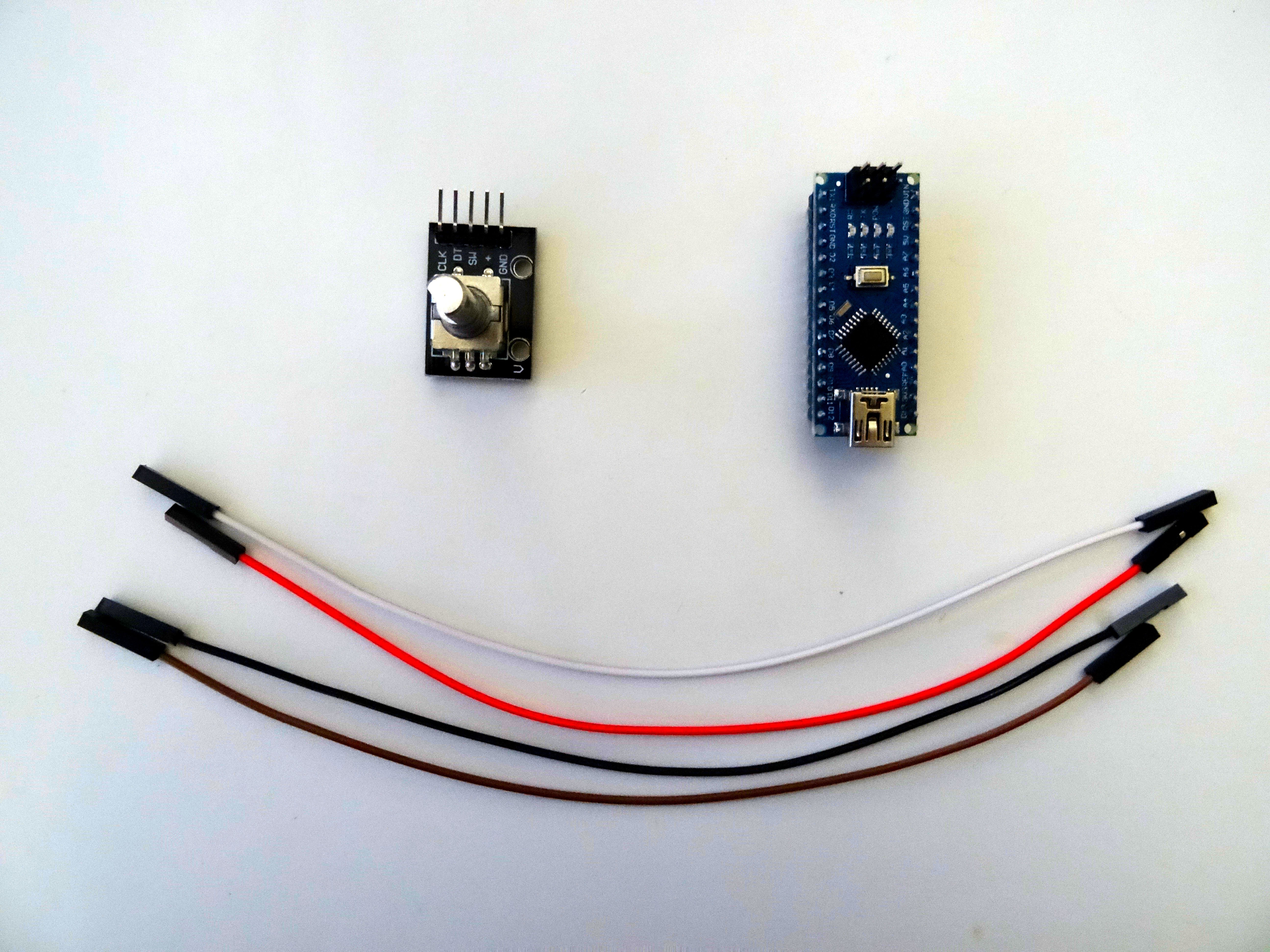
Components
![]()
- One Arduino compatible board (I use Arduino Nano, because I have one, but any other will be just fine)
- One Rotary Encoder module I got from this cheap 37 sensors set.
- 4 Female-Female jumper wires
-
2Step 2
Connect the Rotary Encoder to Arduino
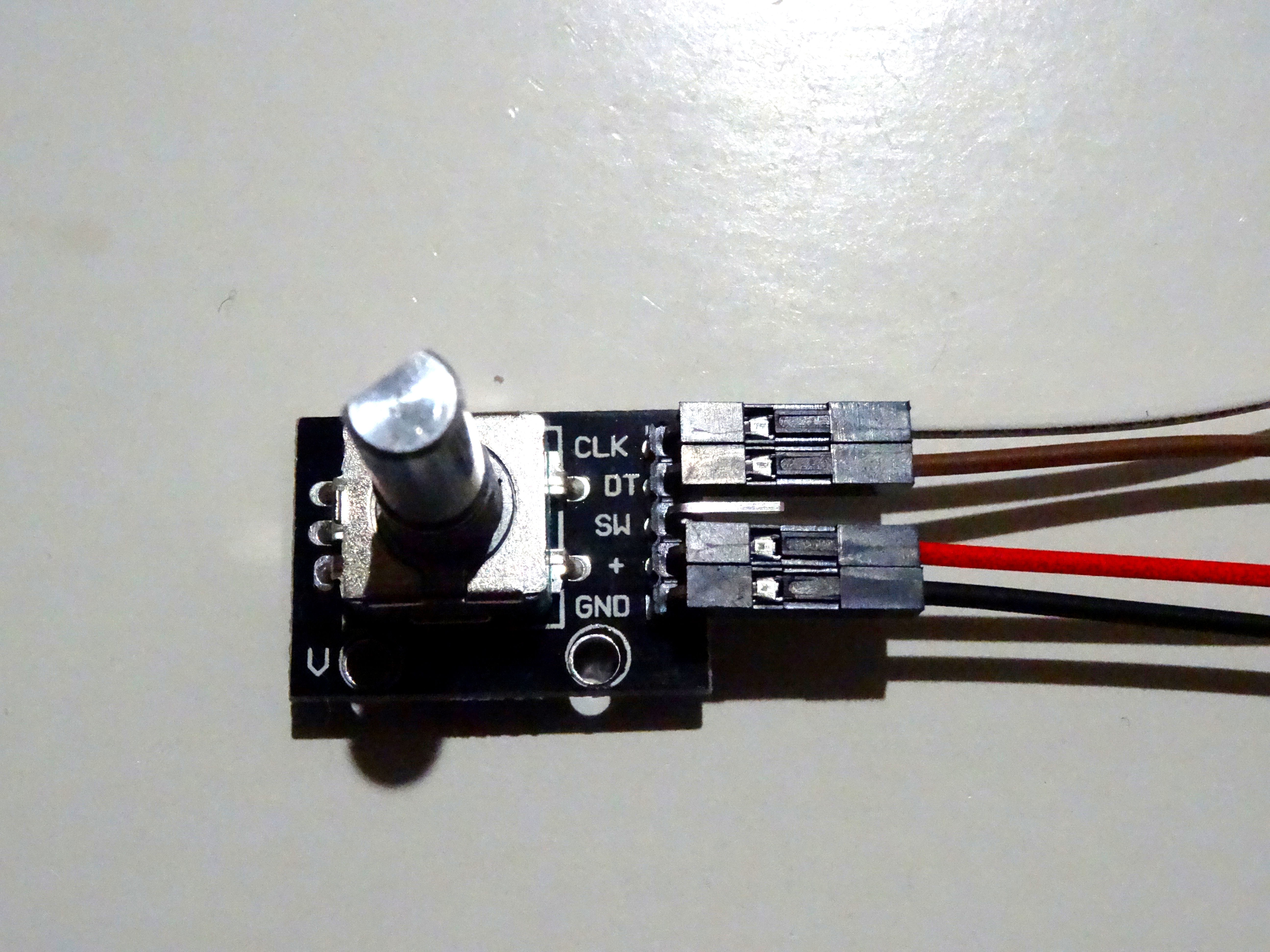
- Connect Ground(Black wire), Power(Red wire), Direction(Brown wire), and Clock(White wire) to the Rotary Encoder Module (Picture 1)
![]()
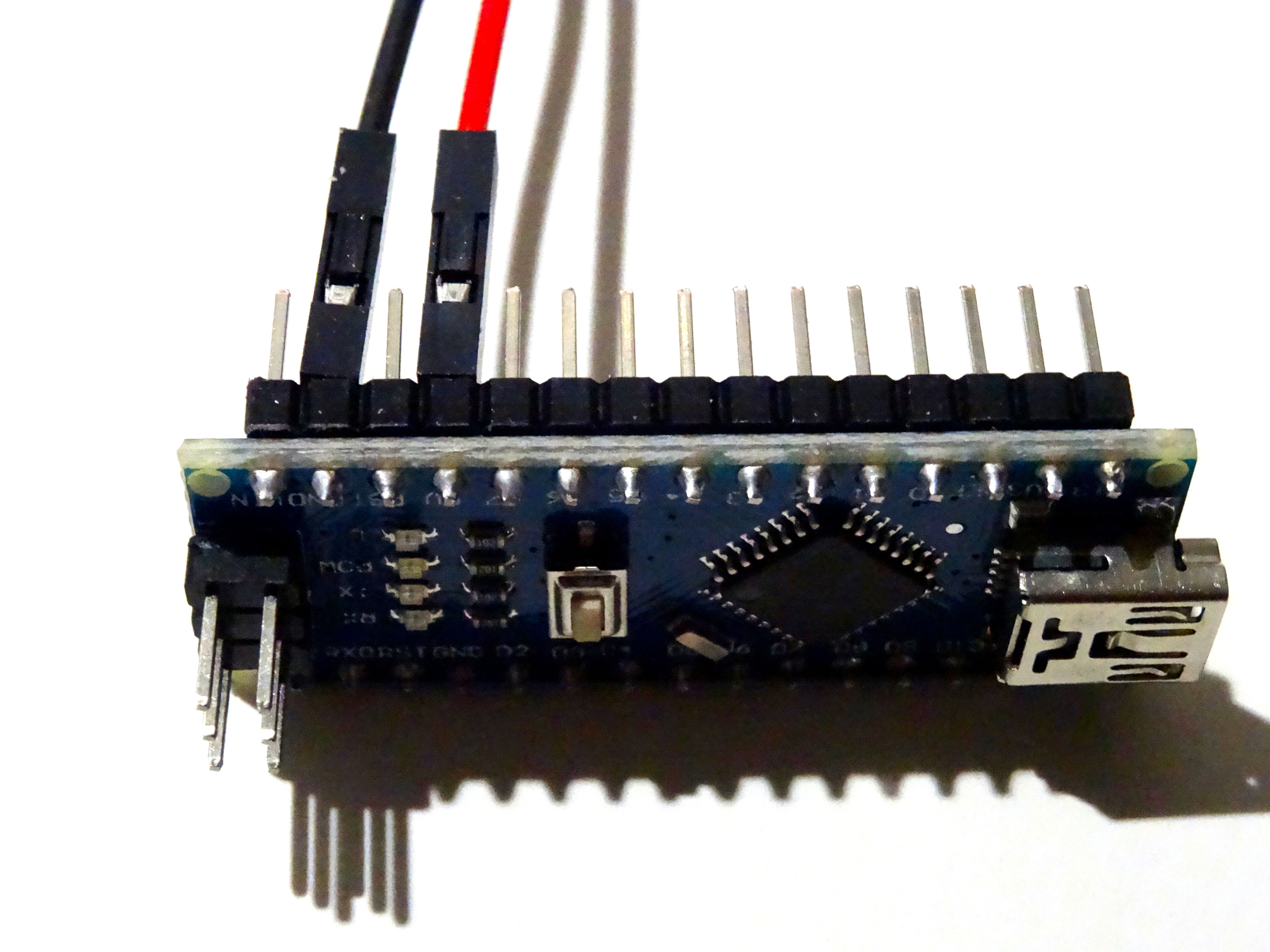
- Connect the other end of the Power wire(Red wire) to the 5V power pin of the Arduino board(Picture 2)
- Connect the other end of the Ground wire(Black wire) to Ground pin of the Arduino board(Picture 2)
![]() Connect the Clock wire(White wire) to Digital pin 2 of the Arduino board(Picture 3)
Connect the Clock wire(White wire) to Digital pin 2 of the Arduino board(Picture 3) - Connect the Direction wire(Brown wire) to Digital pin 3 of the Arduino board(Picture 3)
![]()
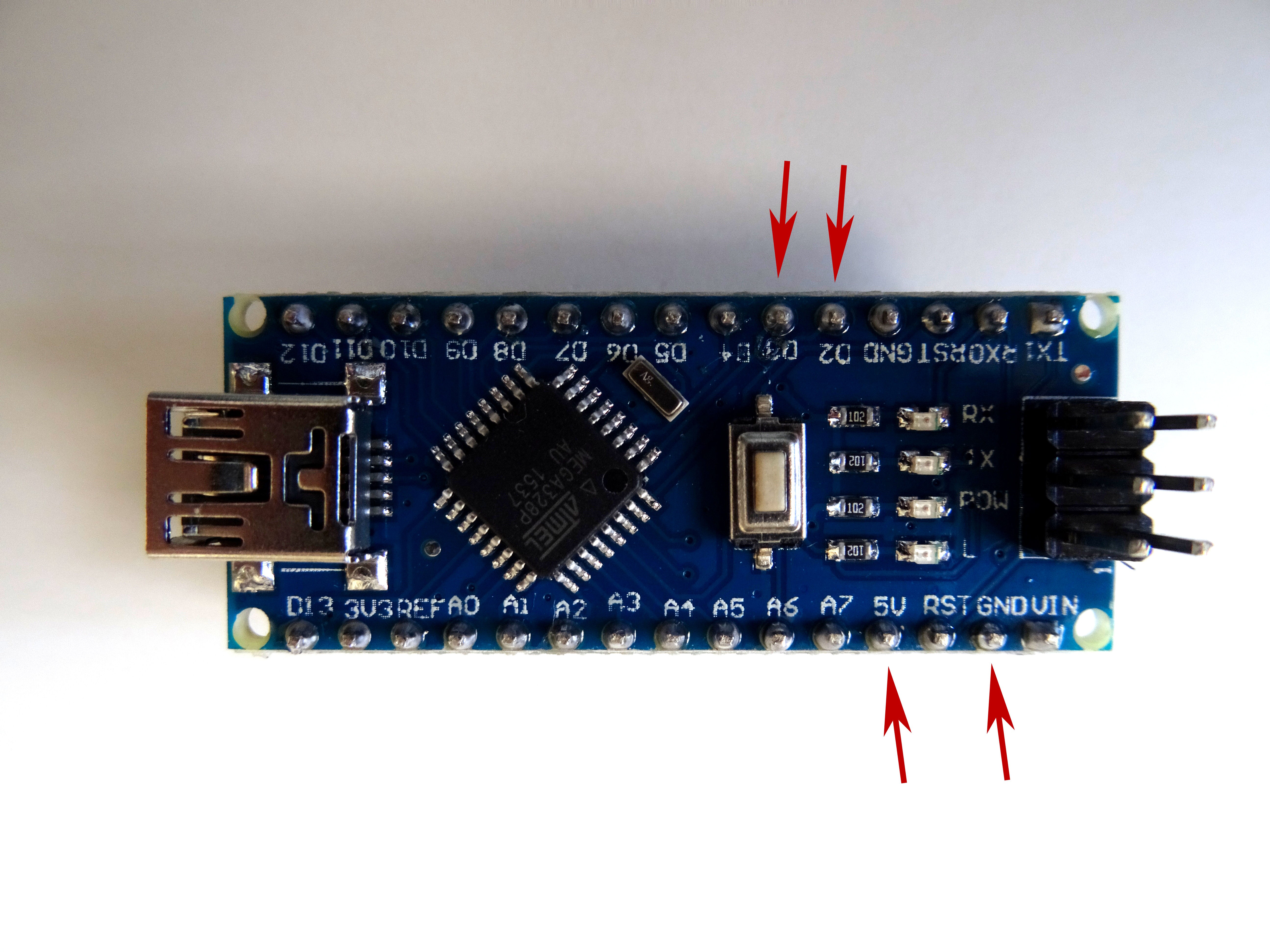
- Picture 4 shows where are the Ground, 5V Power, Digital 2 and Digital 3 pins of the Arduino Nano.
![]()
- Connect Ground(Black wire), Power(Red wire), Direction(Brown wire), and Clock(White wire) to the Rotary Encoder Module (Picture 1)
-
3Step 3
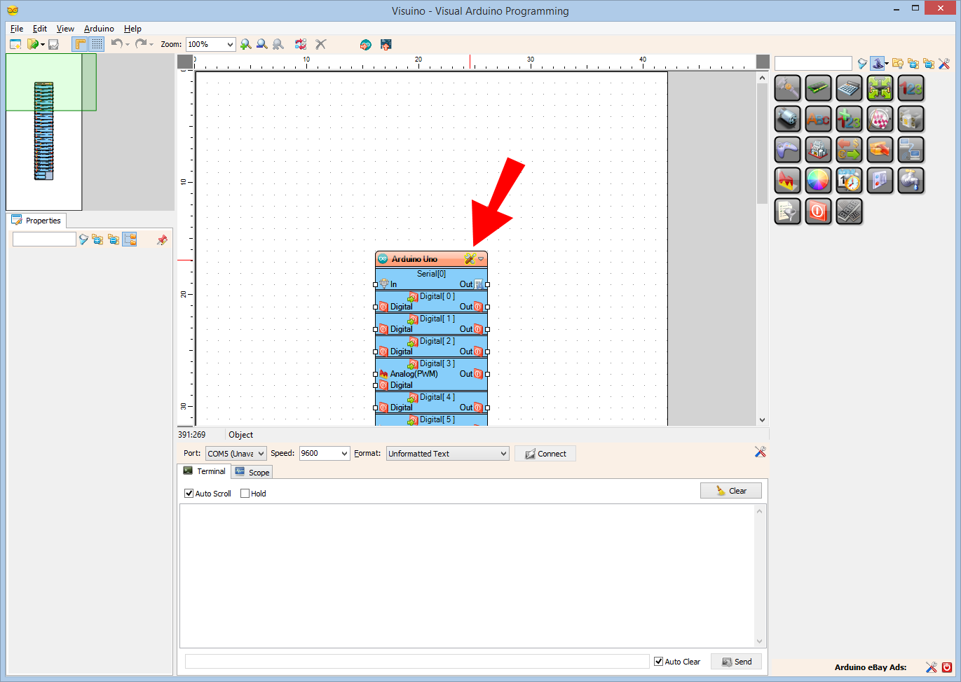
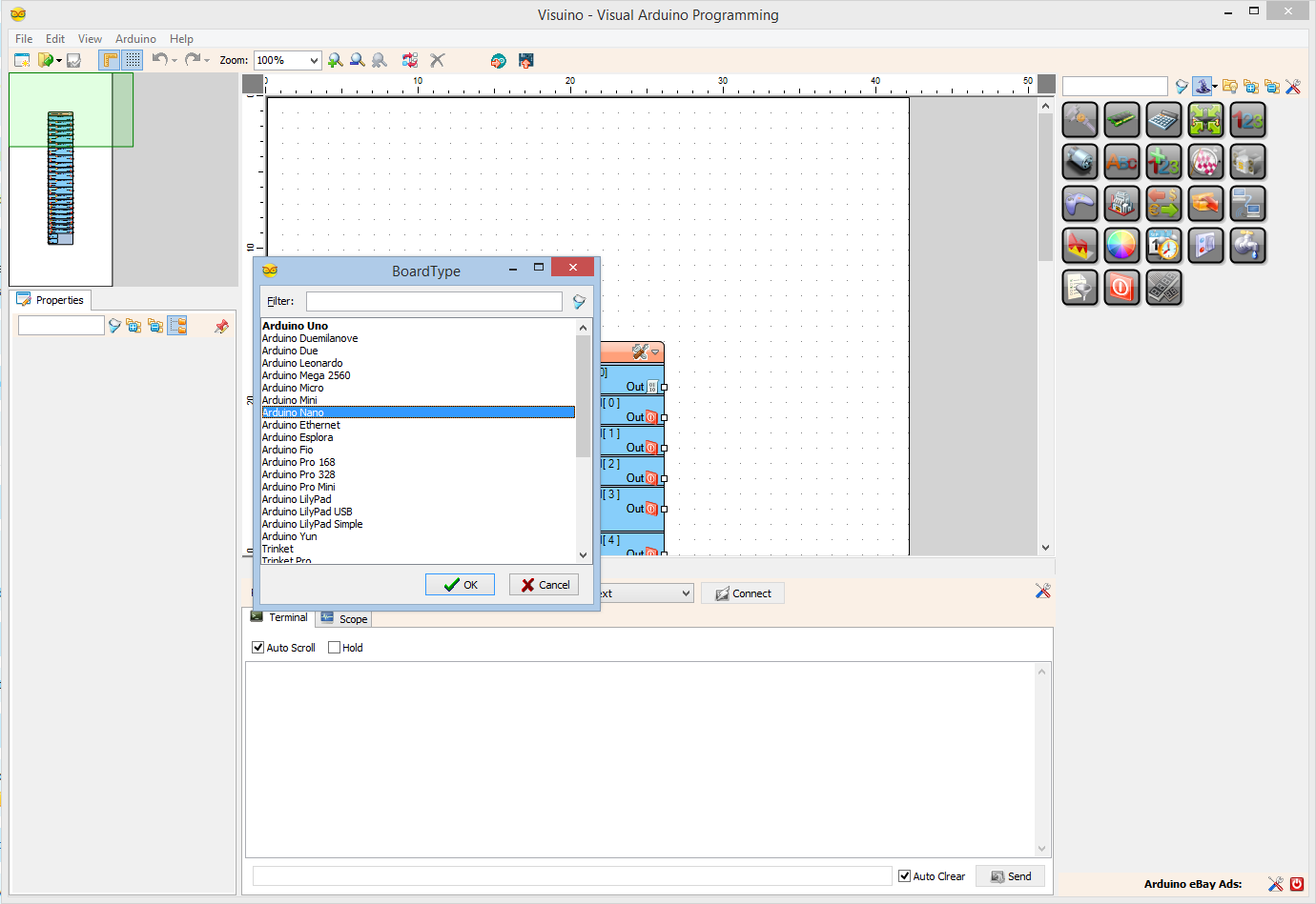
Start Visuino, and select the Arduino Board type
To start programming the Arduino, you will need to have the Arduino IDE installed from here: http://www.arduino.cc/ .
Please be aware that there are some critical bugs in Arduino IDE 1.6.6. Make sure that you install 1.6.7 or higher, otherwise this Tutorial will not work!
The Visuino: https://www.visuino.com also needs to be installed.
-
4Step 4
In Visuino: Add and connect Rotary Encoder component
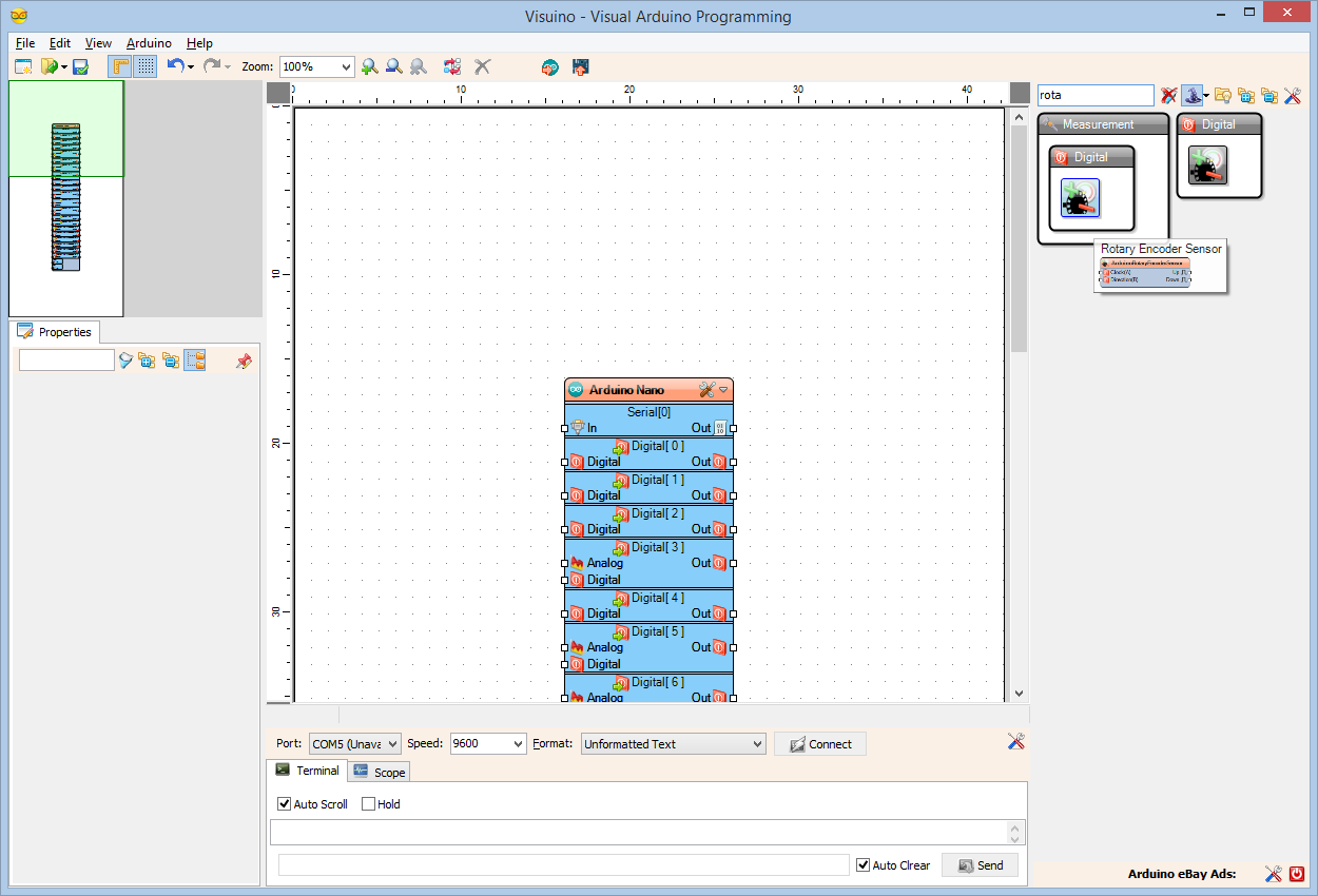
- Type "rota" in the Filter box of the Component Toolbox then select the "Rotary Encoder Sensor" component (Picture), and drop it in the design area
![]()
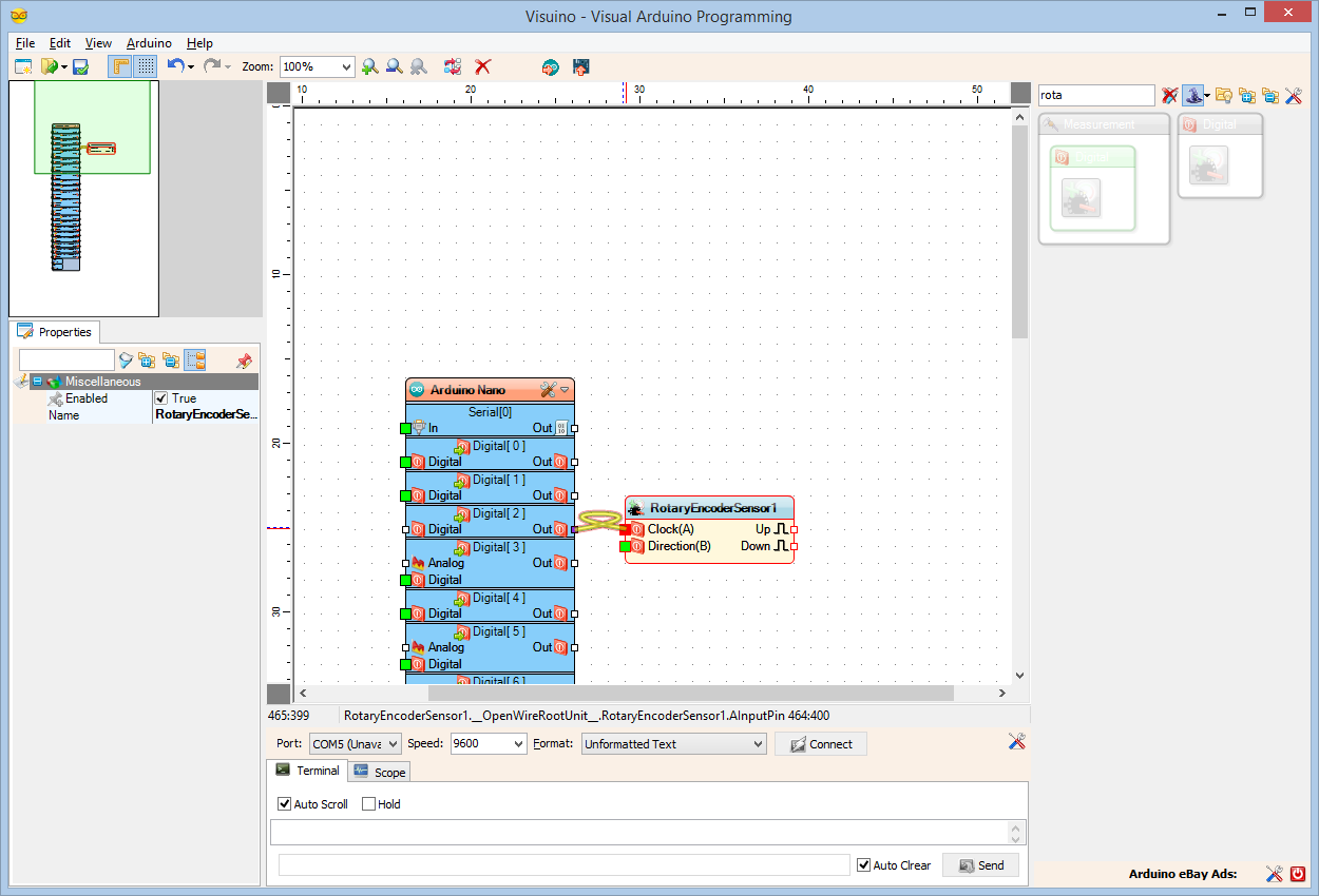
- onnect the "Out" pin of the Digital[ 2 ] channel of the Arduino component to the "Clock(A)" pin of the RotaryEncoderSensor1 :
![]()
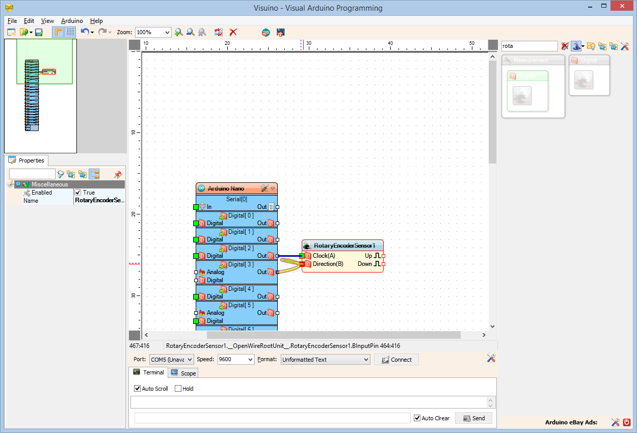
- Connect the "Out" pin of the Digital[ 3 ] channel of the Arduino component to the "Direction(B)" pin of the RotaryEncoderSensor1 :
![]()
- Type "rota" in the Filter box of the Component Toolbox then select the "Rotary Encoder Sensor" component (Picture), and drop it in the design area
-
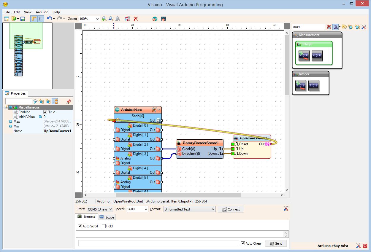
5Step 5
In Visuino: Add and connect Up/Down Counter component
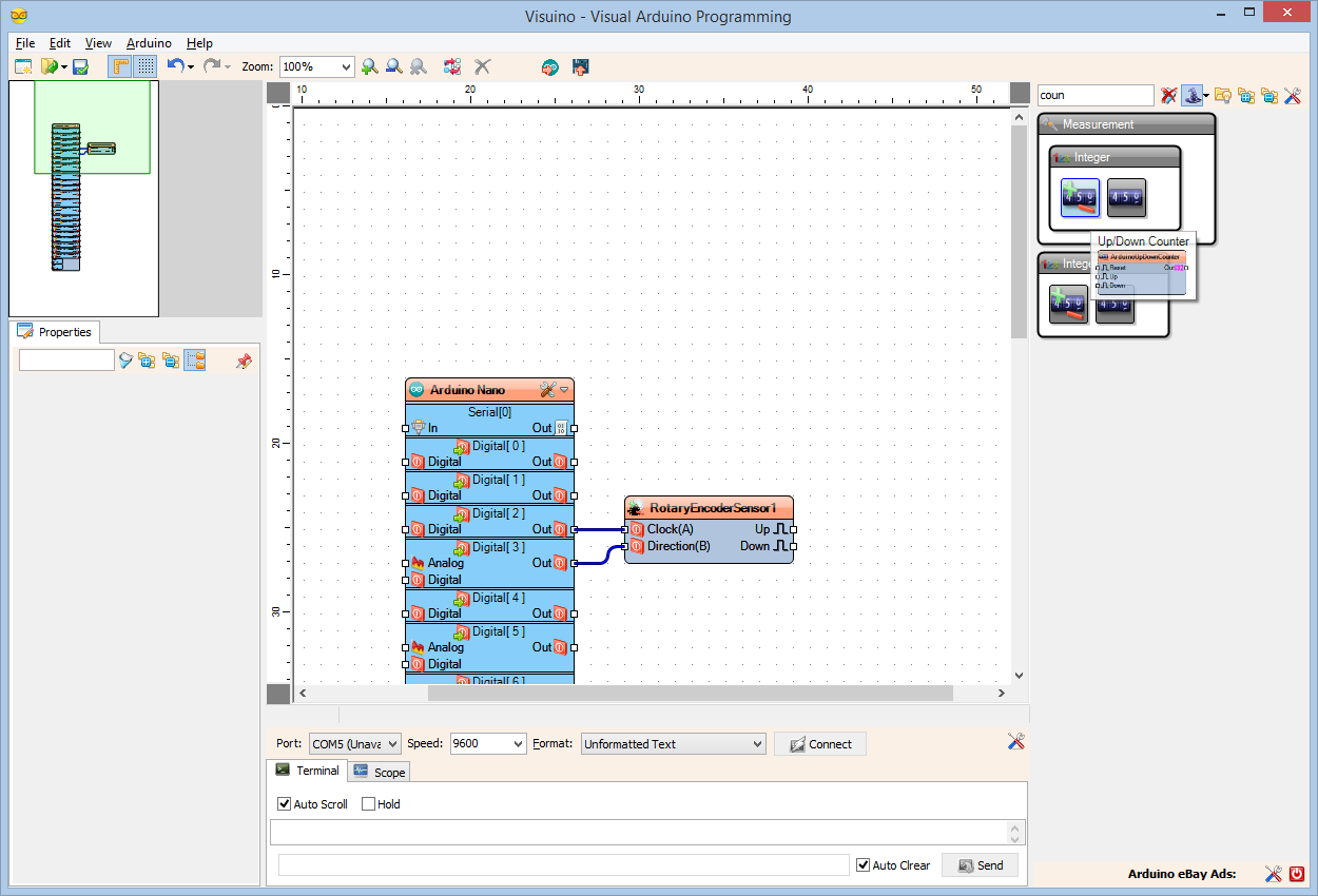
- Type "coun" in the Filter box of the Component Toolbox then select the "Up/Down Counter" component (Picture), and drop it in the design area
![]()
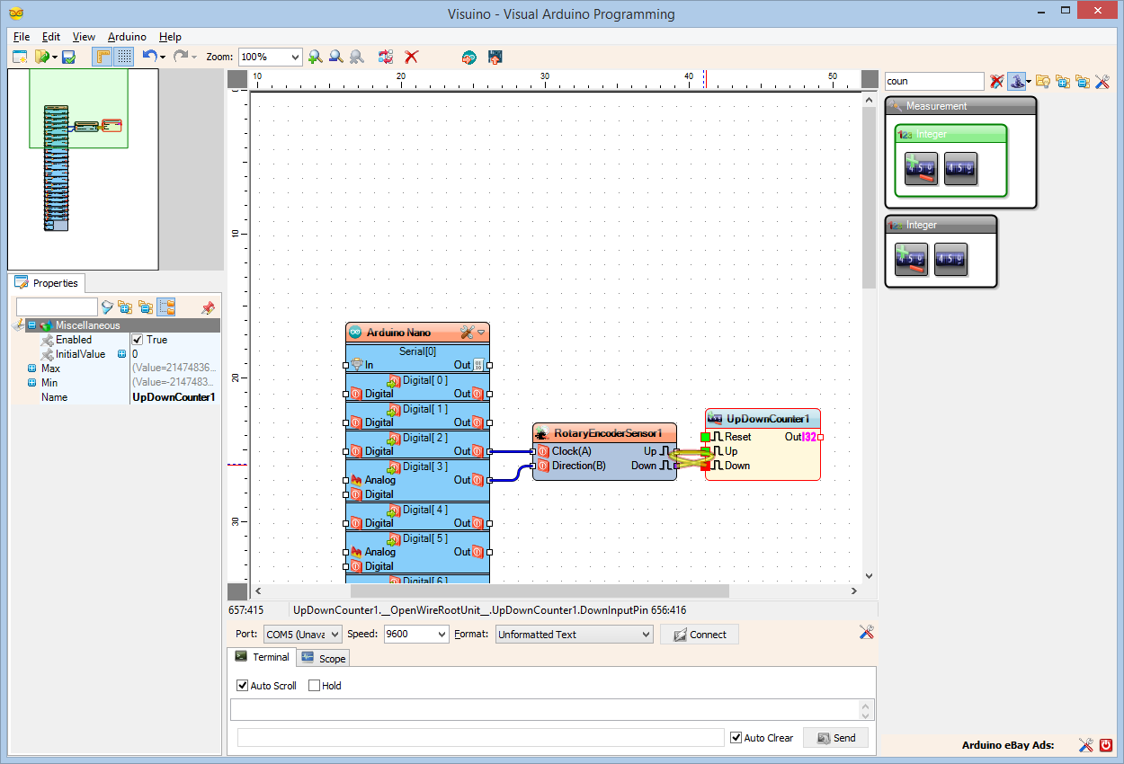
- Connect the "Up" pin of the RotaryEncoderSensor1 component to the "Up" pin of the UpDownCounter1 component:
![]()
- Connect the "Down" pin of the RotaryEncoderSensor1 component to the "Down" pin of the UpDownCounter1 component:
![]()
- Connect the "Out" pin of the UpDownCounter1 component to the "In" input pin of the Serial[ 0 ] channel of the Arduino component:
![]()
- Type "coun" in the Filter box of the Component Toolbox then select the "Up/Down Counter" component (Picture), and drop it in the design area
-
6Step 6
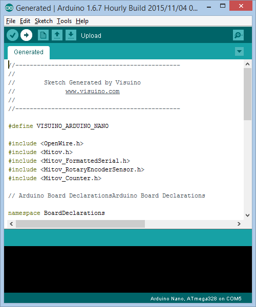
Generate, Compile, and Upload the Arduino code
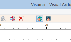
- In Visuino, Press F9 or click on the button shown on the Picture to generate the Arduino code, and open the Arduino IDE
![]()
- In the Arduino IDE, click on the Upload button, to compile and upload the code (Picture 2)
![]()
- In Visuino, Press F9 or click on the button shown on the Picture to generate the Arduino code, and open the Arduino IDE
-
7Step 7
And play...
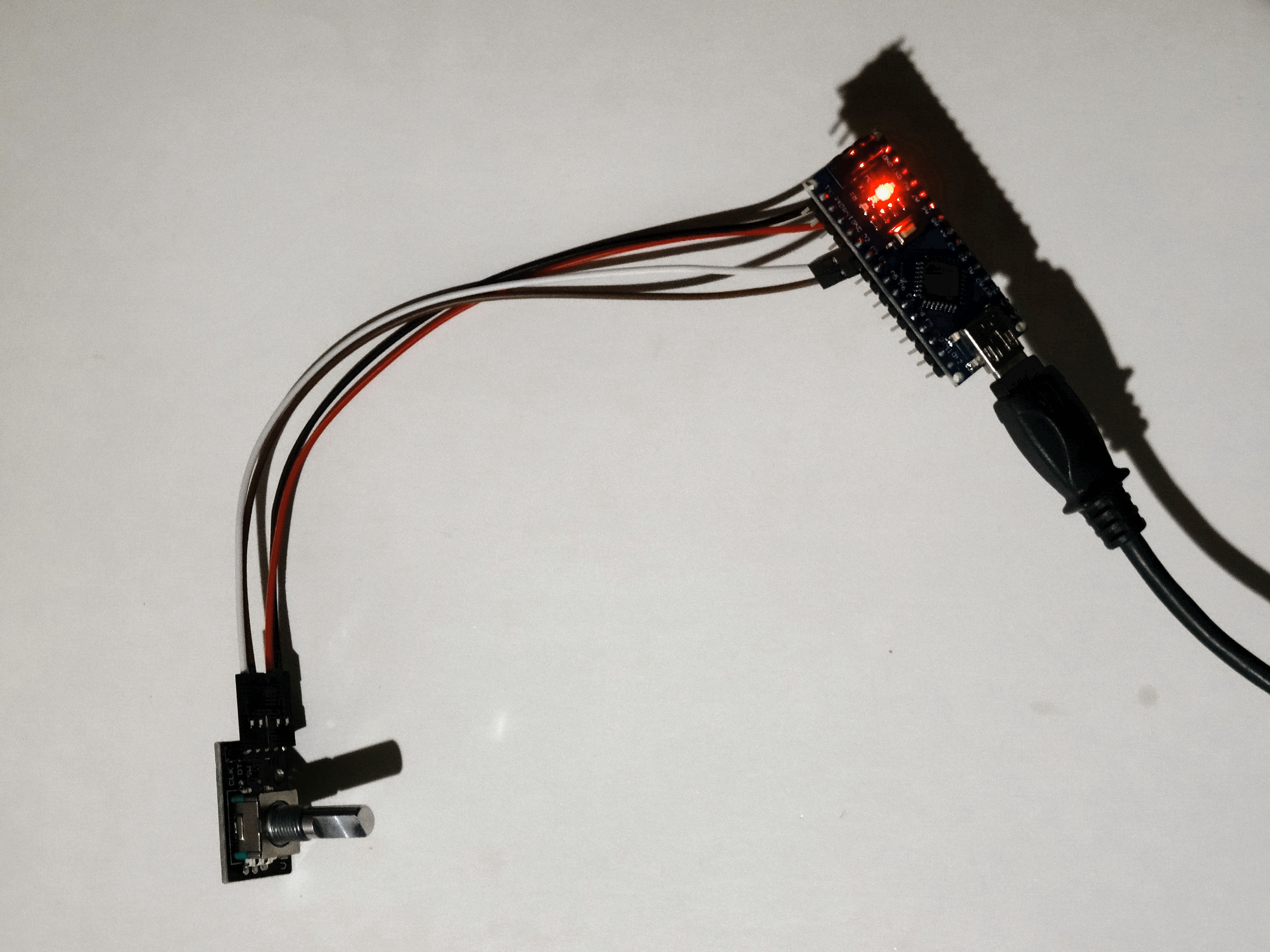
Picture 1 and the Video show the completed and running project.
![]()
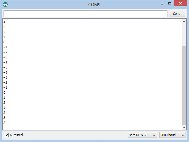
If you connect to the Arduino with Serial Terminal from the Arduino IDE or Visuino and then rotate the encoder back and forth, you will see in the terminal the value of the counter showing the encoder changes (Picture 2)
![]()
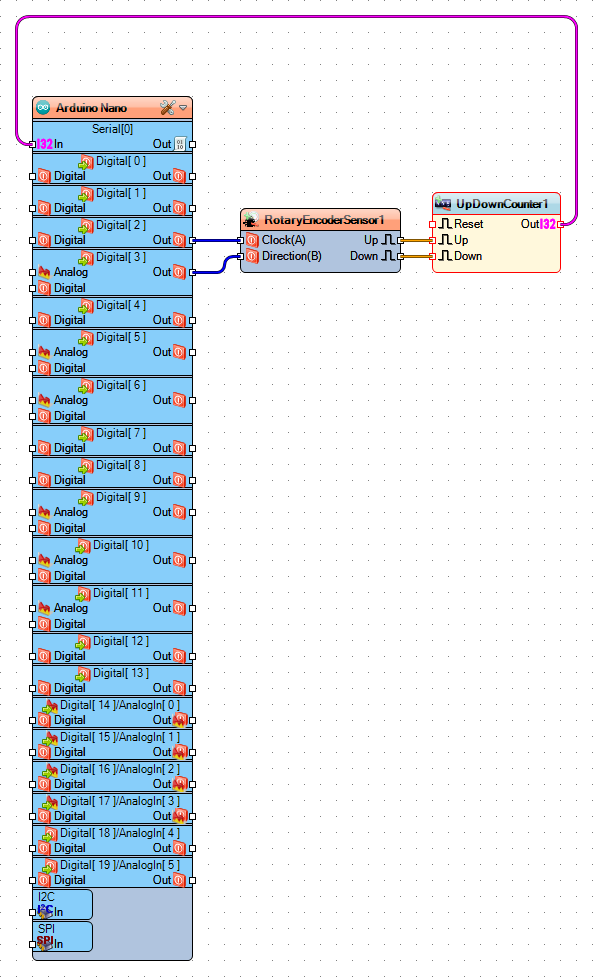
On Picture 3 you can see the complete Visuino diagram.
![]()
Congratulations! You have learned how to connect Rotary Encoder to Arduino, and how to read it.
Also attached is the Visuino project, that I created for this Tutorial. You can download and open it in Visuino: https://www.visuino.com
Arduino Nano: Rotary Encoder with Visuino
Connect Rotary Encoder to Arduino, and program it - quick and easy
 Connect the Clock wire(White wire) to Digital pin 2 of the Arduino board(Picture 3)
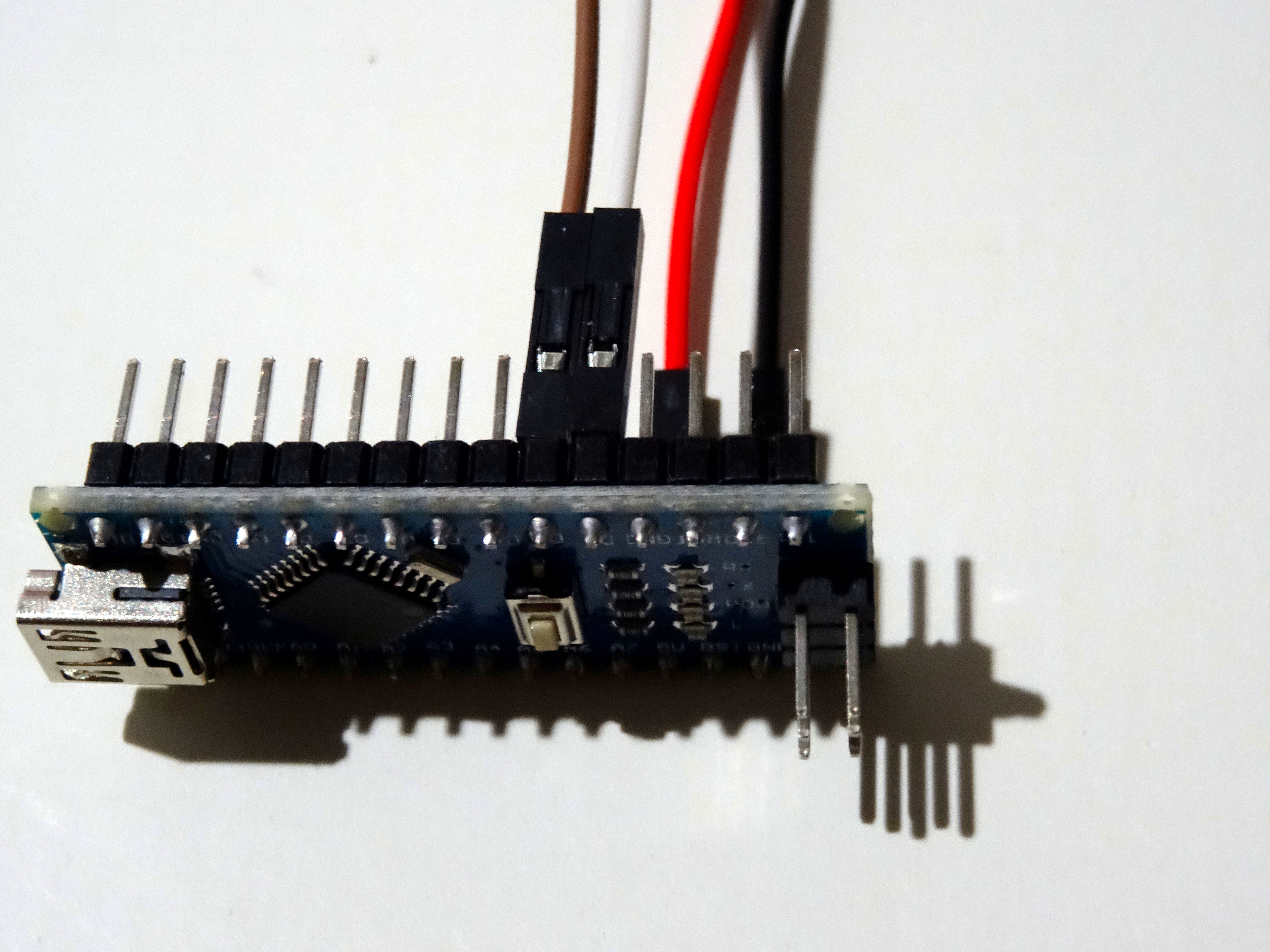

Discussions
Become a Hackaday.io Member
Create an account to leave a comment. Already have an account? Log In.