Close
0%
0%

DIY Space Grade Cyber Space Suit

AKA - Cyince

Similar projects worth following
This project is about the art of building Cyberspace Decks as defined by Gibson. Real honest to gosh effective hardware that allows one to move in cyberspace by thought alone. Along the way the journey also seems to provide what I believe will be effective solutions for a whole range problems in prosthetic devices and molecular biology and I'm sure many, many more.


Cyince is a switched fabric network for processing large signal ensembles, in this case related to the brain/body. The number of signal sources and their individual bandwidths are arbitrary, limited in most cases by weight, primarily batteries, and not signal density. Sensors include the usual variety of electro physiological processes, MEMS accelerometers, gyros, force transducers, cameras, microphones, speakers, displays. In each case, the end point of the network will be either a sensor, or actuator that interfaces to the system via a specialized connector designed to support signal, power, and fluid transport.

The fabric is strictly peer to peer. While in many cases there is "host" as in a connected workstation that provides a convenient focal point for system configuration, data collection, analysis and study it is not necessary for operation of the device.

There are three primary applications of Cyince that are of major interest:

(1) As an infrastructure supporting a wide variety of prosthetic devices and/or (2) As a cyberspace deck for navigating the net without movement by thought alone. It is the movement in a virtual reality without a corresponding movement in physical reality that is THE problem. (3) As the primary signal process component in a new class of "Lab on a Chip" devices.

Before describing the instrument and it's architecture it may be useful to describe some of the harsh reality of biological signal processing.

Basically you might think of the body as electrified salt water Jello. A signal generated, say from a muscle in the eye, may be measured everywhere. This is true for every other signal source. It's called the Cocktail Party. The challenge is to deduce an individual conversation from a ensemble of the same. Fortunately each of these conversations is separable using a process called Independent Component Analysis (ICA).

The control vectors are derived from a deep learning network that uses the EEG, EMG, and MEMS as inputs with a belief that there is a causal relationship between the three.

So, it seems that EEG sciences got themselves into a really bad habit. You see, back in the beginning, around 1926 when the very first 6-channel differential amplifiers based EEG systems were available, they were the size of desks. Experiments were performed with patients lying on beds. Then, some time around the 1960, people got civilized and started sitting in chairs wearing electrode caps with wires running off to a box. Unbelievably, over 50 years later, subjects are still sitting in chairs with caps and wires running off to a box. It is in fact iconic. The image, perhaps a artistic shadow image of someone sitting in a chair with electrode wires, streaming off their head, like a great mane of hair. Pretty image, freaking primitive way to process bio signals.

The challenge is to measure low level signals while going about your normal day. Walking, talking, driving, shopping, playing golf. That is the natural expression of the symbiosis between brain and body. I believe the effective study of the brain requires that the simultaneous measurement of movement is essential to understanding the entire being. So, if you want to build an effective neural prosthesis it is absolutely essential that you start with the study of complete working systems. Presently, this is not the case. I'd like to think that this problem persists because it is a hard problem.

It's easy enough to measure 16 channels of pretty much anything. But how do you build an instrumentation system that supports thousands of channels of all sorts and descriptions, of all manner and type and signal level and impedances, and get it inside the memory space of a GPU with minimal latency while still being able to wear the device comfortably as though it were as ordinary as a pair of jeans?

Today we see countless examples of the application simple phenomena related to the EEG for simple controls. The most common application being alpha rhythm control. Eyes open...

Read more »

  • The latest in Cyber Fashion

    Chuck Glasser10/03/2016 at 06:22 0 comments

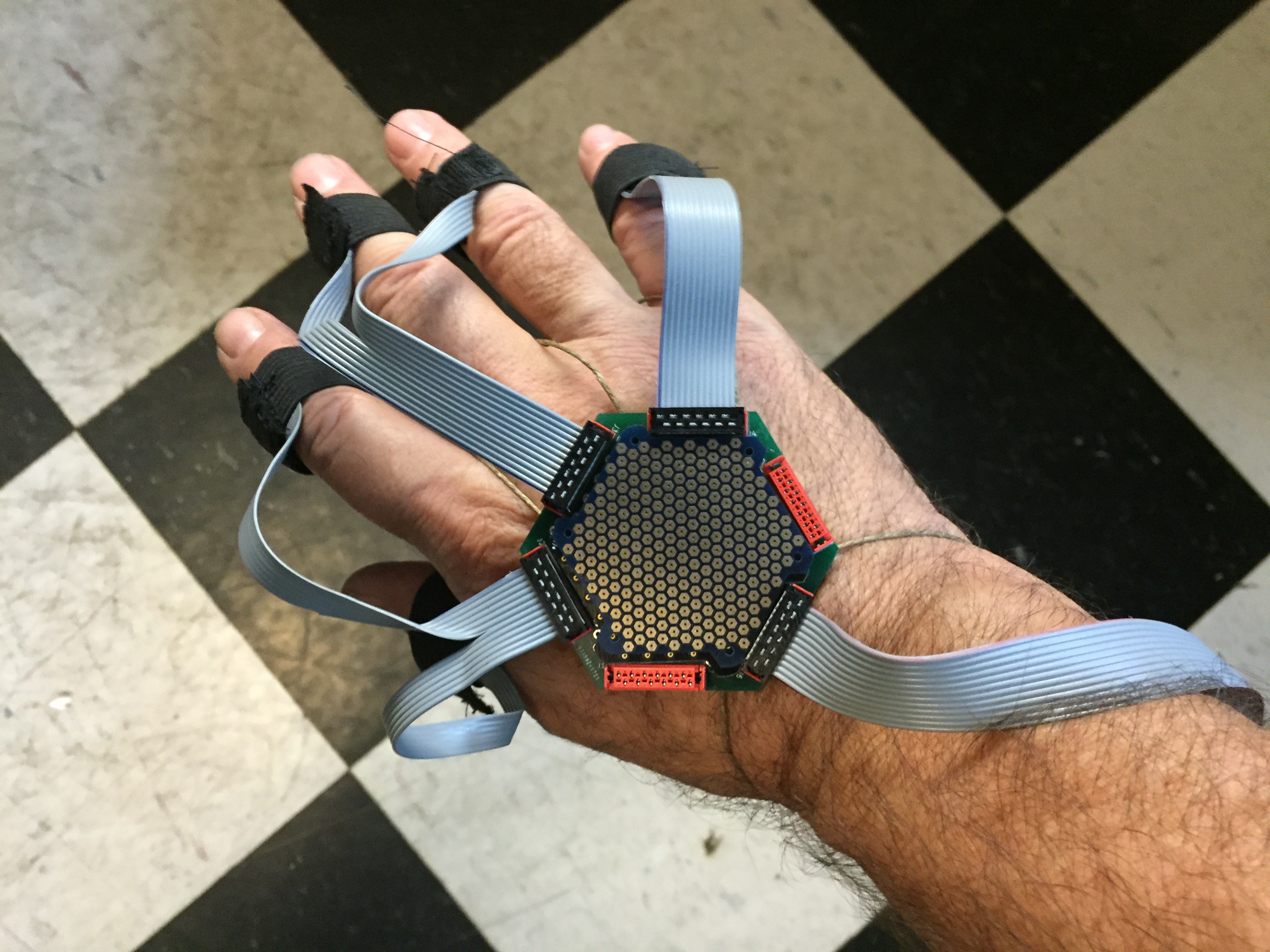
    Since I have no boards to debug until Tuesday, I thought today I'd start work on the data gloves that captures body motion. I'm pretty sure every data glove designer started out with something like this. I seriously doubt they had anything within 4 orders of magnitude as fast as represented by the token over the back of my hand.

    The cable dress is going to need some work. Otherwise it is very comfortable.

  • Signaling architectures

    Chuck Glasser09/15/2016 at 07:36 0 comments

    You may have noticed in the last few years an absolute deluge of little modules that do something. Got an idea. Grab a few modules that do something, hook up a little Embedded Micro System (EMS) like an Arduino, Beaglebone Black, or my present favorite, the FPGA based Snickerdoodle. Later, ranging from minutes to years, you've got your gizmo.

    But there is a problem. Whatever, EMS you've chosen has a limited number of I/O ports that may be exploited. Lets say the EMS has 8 SPI ports. But you need 9. What do you do then? OK I've got 2 of them. How should they communicate with the client? Or each other. Ethernet, CAN, RS-232, RS-485, ... etc. But, in fact, each of those communication methods, is really nothing more than a port.

    What is the best way to abstract the I/O hardware within a system such that it scales without bound while abstracting the physical interfaces to be totally agnostic as to the type and bandwidth of a signal. While it might be possible to build a bit of front end electronics that was universal. It makes more economic sense to normalize the upward facing port. I've elected to use an 8 signal wire, 2 gnd, 2 power, fully symmetric connector implemented in a Micro-Match.

    Signals are arranged as

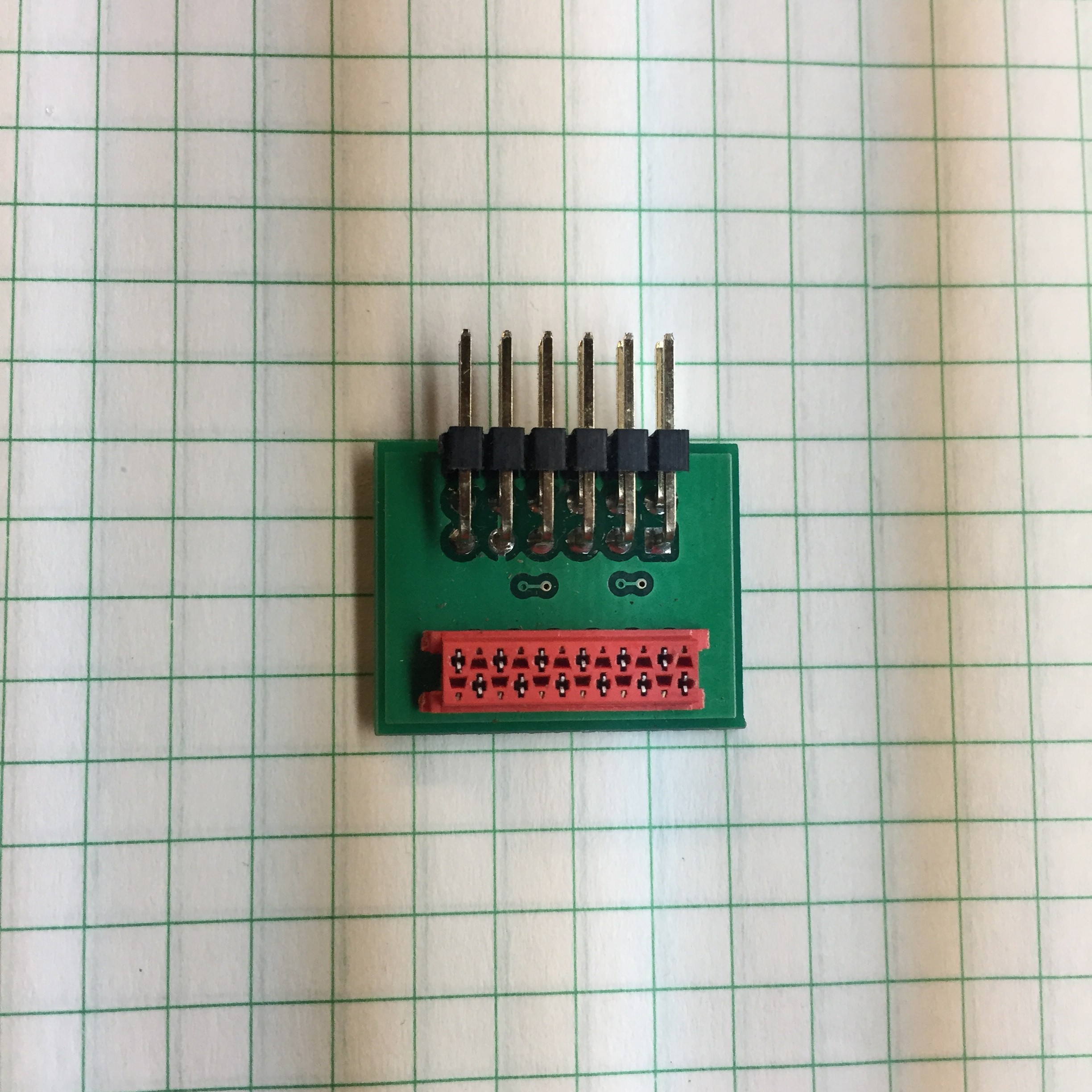
    VBus 1, Sig1, Sig2, Gnd, Sig3, Sig4, Sig5, Sig6, Gnd, Sig7, Sig8, VBus2 and coincidently mate well to Digilent's PMOD interface with this adapter.

    The other end might look like this.

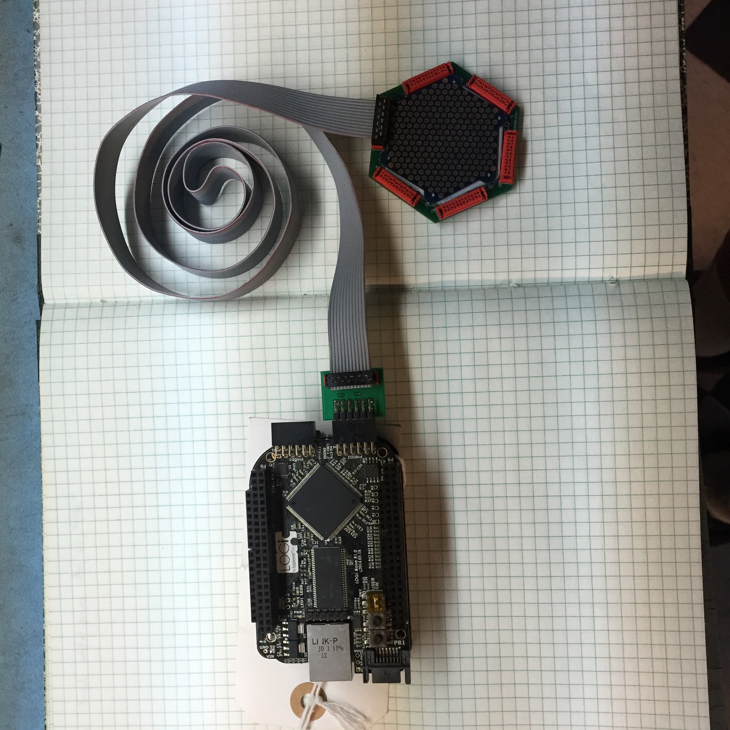
    Here is what my minimal system looks like.

    Shown are a Beaglebone Black with a ValentFX LogiBone FPGA board. Communications to the Token is absolutely arbitrary. If the Token is a switch then the maximum data rate is easily above 200 Mb/s. If it is a ADS1299 token then the available 8 signal are configured as a SPI interface.

  • CyberSpace Suit Design

    Chuck Glasser09/06/2016 at 04:24 0 comments

    Perhaps you were driving down the road one day, arm out the window, enjoying the day and you later found yourself waking up in a hospital in this situation. Bummer.

    So if you had a really nice, prosthetic arm, how exactly are all those servo motors and other miracles of miniature mechanisms controlled?

    One thing is almost a certainty, at least for this day and age, a 100% certainty. There are going to be electrodes somewhere in the system. To be effective, the electrodes must remain in electrical contact with those regions for which the electrode is responsible to provide a signal, always.

    I have a friend who found his foot between a fence post and the bumper of a car. Now he doesn't feel his foot from mid calf on down. Walks with a sleepy foot gate. No wonder!

    Now suppose there was a sock that he could put on, a CyberSock if you please, that restored the missing sensory feedback. Perhaps, he'll take up dancing again.

    At days end, he takes off his CyberSock, and throws it into the wash. It has to be that way incidentally. Or, the disassembly, assembly of the cyber part of the sock has to be so fast and easy as to be trivial.

    So, ... the CyberSpace Suit is an extension of the sock. Instead of transducing forces around the foot, the suit measures everything, everywhere. What holds all the various parts of the system together is the sock, a membrane with the body on one side and the world on the other.

    Pictures to follow.

    There is another membrane. The skin. We should expect that the realness of the sensation of the foot depends upon the expertise with which the peripheral nerves are stimulated by an implantable device, that communicates through the skin. Ultimately, the function of the sock is absorbed, becoming entirely implanted. But what of the condition when there is no foot and only a marvel of plastics, composites, and steel?

  • Finally, it's time to make some electrodes.

    Chuck Glasser09/05/2016 at 03:48 0 comments

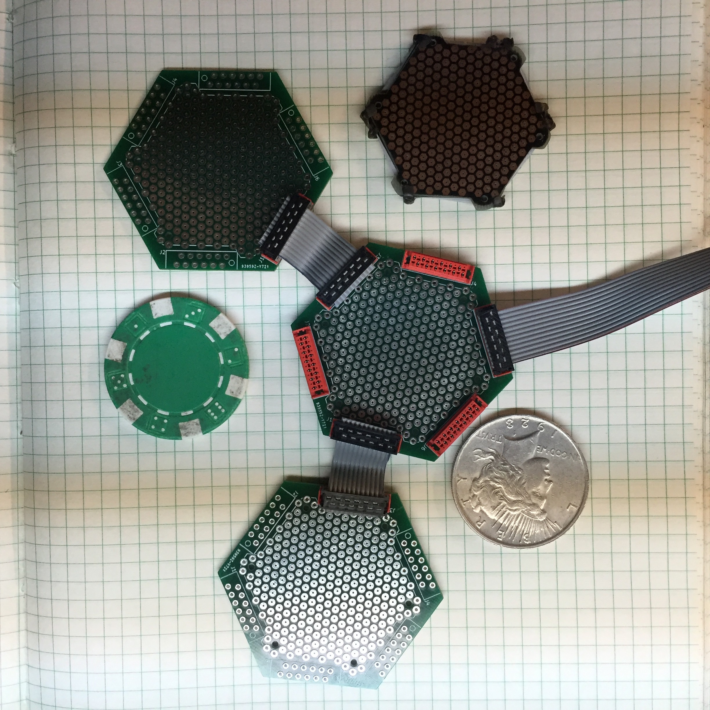
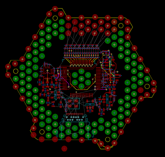
    So here is what the final ADS1299 Layout looks like.

    As a point of reference for scale, a poker chip just fits within the boundary of this pattern.

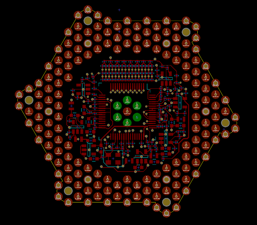
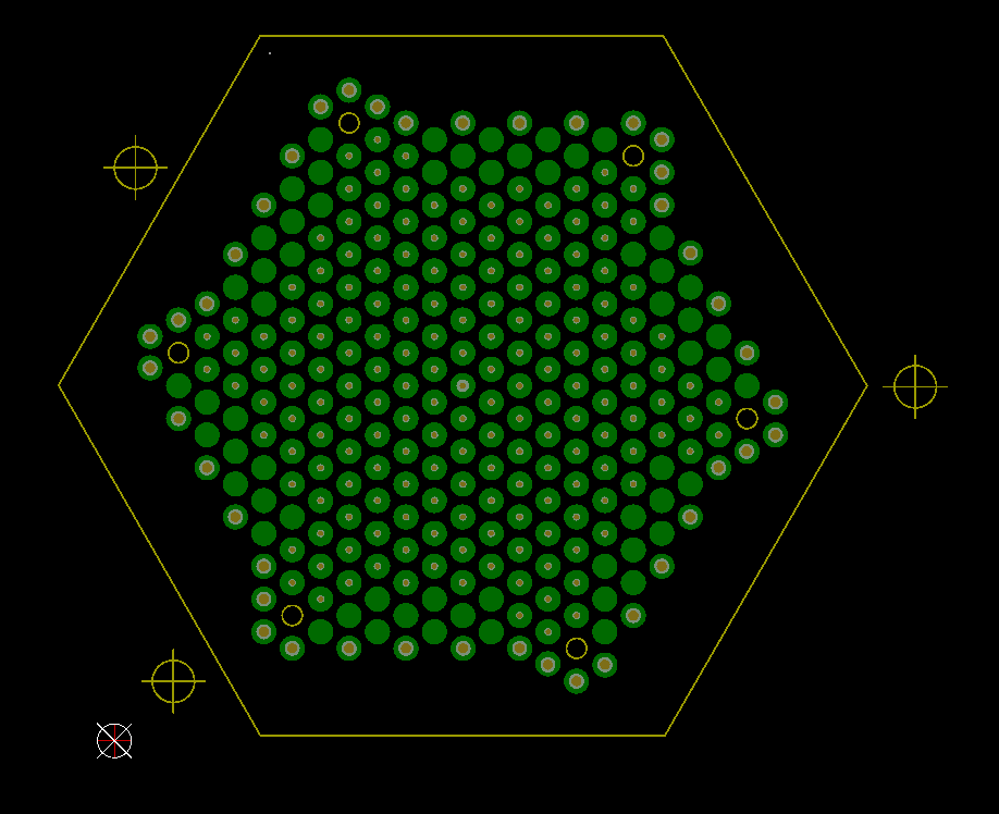
    So something of an explanation. If the circuitry were missing and there was only the pattern of pads, each 2mm in diameter, then there are 241 pads per side. for a total 482 possible points of signal or power connection. That's a lot of pads!

    The artwork looks like this.

    It looks like that on the other side. Take my word for it.

    So the ADS1299 circuitry within a token is encapsulated top and bottom by two surfaces with this pattern.

    The data switch looks exactly, well almost exactly the same.

    All the components in the system look the same. Just a bunch of tokens that are stacked on top of each order. With nothing to distinguish them from each other, other than a hidden code known only to wizards such as myself.

    Each token, having it's own special function while also having the ability to communicate with other tokens anywhere within the system.

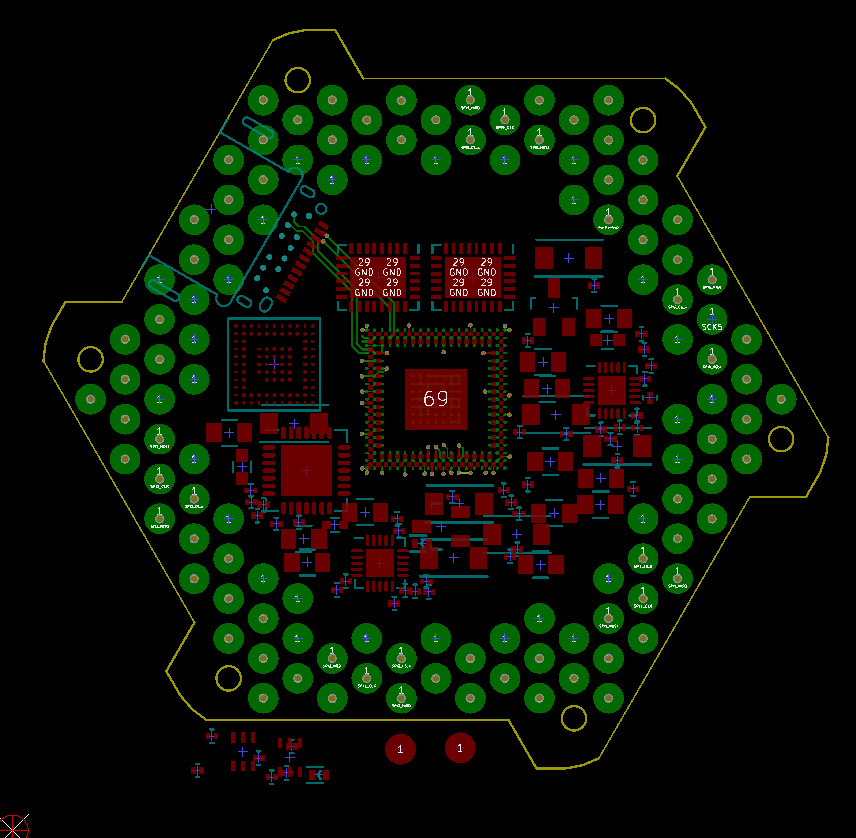
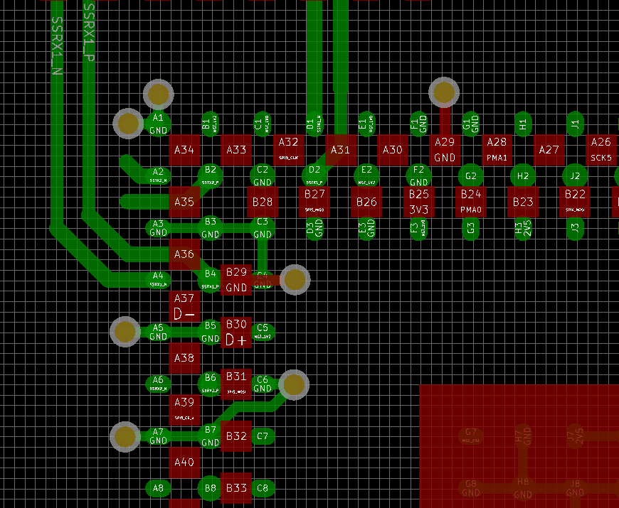
    That's a USB3.1 C connector that offers 100 Watts of power and 40 Gb/s, the FPGA, a Xilinx XC7A35T in a CPG236 package. The layout follows 4mil design rules.

    Here is the really great part. Check out how nicely the XC7A35T Artix FPGA matches up against what I think is an absolutely great embedded processor, the PIC32MZ.

    The PCB capture is done using Kicad. Really, really like Kicad!! I've used many PCB tools in my career, Kicad is very nice. Takes practice like most things to be effective. After a time I've begun to understand it's quirks.

    This graphic illustrates how nicely the FPGA in green marries up against the PIC32MZ in red using 4 mil design rules.

    Each of the devices discussed so far is about the thickness of a poker chip, with similar weight. So, if you stack them in the correct order. That would be, electrode, electrode amplifier, and switch, then there is a complete signal processing chain going from a simple, multichannel precision, low level differential voltmeter, to an interface that in theory does 40 Gb/s. A system of instrumentation that is literally so fast that data from a whole array of sensors disappears into the data cloud within a single clock cycle of the original sensor data clock.

    So, back to the electrodes. Now that I know what the pattern of contact for the electrodes are, as expressed in the ADS1299 circuitry, I can proceed on the layout of the LTCC artwork.

  • Horray, the latest boards are in from Dirty PCB

    Chuck Glasser08/31/2016 at 05:19 0 comments

    The two outstanding PCB have come in from Dirty PCB, love those guys.

    Just a little advice, pay for DHL. Fast...

    Here is the latest board. Not quite ready to go out.

    This is a 4 - Layer PCB for an ADS1299. This is also the challenge design for DIY Space Grade PCB. Build a matching Electrode Array to this pattern.

    The hexagonal pattern is a key component of the design.

    You'll see it over, and over, and over again. I love the hexagon!

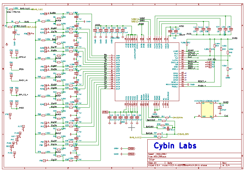
    If your curious, here's a schematic, sans the power page, but an exact copy of the TI notes.

    Keep in mind that the board has not gone to press.

    In a couple of days, perhaps tomorrow I'll be happy with the circuits I have wrought and will send it off. In about 10 days the DHL guy will hand me a package. Nice!!!

    ... Weeks later, Dirty PCB could not deliver boards with castellated edges. Bummer. Hand to switch to a new vendor who apparently will deliver, via DHL, my amplifier boards on 10/4/2016. Oh the irony!

  • Day 1-3

    Chuck Glasser08/23/2016 at 06:08 0 comments

    Let's see, 5 x 7 is 35 days. Better make the best of them! Today was consumed by wrapping up the AmpToken-II pcb using Kicad. I really like Kicad. This AM I managed to get the Java program FreeRouting up thanks to the efforts of this brilliant fellow. I've worked so hard over the years to avoid learning Java, but NetBeans looks nice. Maybe I should reconsider my bias.

    The AmpToken-II board is a ADS1299, 8 - channel EEG amplifier is almost done. Really tricky layout, lots of 0201 components. Thankfully, the vacuum pickup on the SG-CNC should allow for easy placement, "in theory and when it's running". I've simply got to get it to the board shop soon or I'll be in big dudu.

    This system is designed for flex circuits. For now, because it is considerably cheaper the optimal solution is to use conventional IDC connectors. Ultimately, at least for a short time this means the electrode count for the head will be slightly less than the usual 350.

    The system support the VR goggles was, sans googles, was made in 1996. I call it the Mark 96. My first attempt at building an EEG helmet was in 1970. It's called strangely, the Mark 70.

    The Mark 16, that would be this year, in it's final operational form, consists of an array of signal processing nodes. Each node is an individual switch within the switched fabric consisting of a PIC32MZ processor butted against an Artix XC7A35T FPGA. Each node includes 1 PCIe port and up to 7 additional slower speed < 20 MHz, sensor ports. In the overall signal flow, and the engineering effort involved, its far easier to use the PIC32MZ for the initial signal processing. The PIC32MZ grabs the data, typically SPI, converts it to 32 floats, formats the data into the outgoing packet and kicks it out to the TX buffer in the FPGA.

    The Mark 16 makes use of the USB-C connector. You know, the connector that does 40 Gb/s which is of course deep into the microwave. Is that COOL or what? In the most direct path the data goes from the sensor to the memory space of a GPU, certainly within the time of a single clock cycle of the data sample clock. I've not worked out exactly how fast the signalling process is, but I would estimate that it takes around 1 uS. The point is that there are no protocols, no network interfaces, no network stack, all of that does not exist.

    The system state is simply a part of the PCIe memory space. Usually it's more effective to copy that data into the GPU's memory space. That will be a happy day.

    Big day tomorrow. The PMOD to Cyince PCB interposers are arriving from China tomorrow. Yea! That means I'll be able to start streaming data via a variety of FPGA Dev systems. I'll start with the already running Beagle Bone Black (BBB) married to a ValentFX Spartan 6. Next in line will be the Artix 7 by Digilent, and then finally the Snickerdoodle with dual ARM 9s running on an FPGA! Last is the fabric nodes made up of the PIC32MZ/XC7A35Ts.

    What I've learned recently is that while compiling directly on the embedded processor is great, and very effective. It may in fact be better to use the cross compiler and keep an image for the embedded process on the host. On that topic I'm not there yet.

    And then of course there is the device tree. For that your going to want to use the XIlinx SDK.

    I feel like this guy.


  • What is Cyince

    Chuck Glasser08/02/2016 at 18:21 0 comments

    If your busy off exploring a virtual reality of some sort with the latest imaging system. Why are you still using hand controls? Would it not be better to just think, and there you are. Is such a thing possible?

    How does one go about building and designing a device that can allow one to move in cyberspace without physical movement of the body. Not so as much as a muscle twitch, not a twitch from the furthest toe to the eyes is there a mechanism. There may indeed be movement but it's not related to translation in multidimensional cyberspace.of your avatar. Incidentally, this is not some old worn out algorithm that uses binary modulation of the alpha rhythm for instance.

    Cyince or CYbernetic INstrument interfaCE, is a distributed instrumentation system that covers the entire body.

    This is going to get a bit confusing here, so let me explain. Answer this simple question.

    Why do we have brains?

    Why do we have bodies?

    Did you answer to the previous question have anything to do with movement?

    Personally, I view the study of the EEG without also measuring movement as a waste of time. A complete and total waste of time! Like measuring the amount of force on the steering wheel. Is it under the control of a Grand Pre Driver or a 5 year old, parked in the garage? Without a context, it could be either.

    Cyince measures three primary groups of data. Around 350 channels of EEG, A similar number of EMG singnals collected by the body suit, and third a acceleration and rates of rotation, with, as needed, magnetic field readings from every degree of freedom. For a single gloved had that would be 56 channels of data, not including pressure against the surface of the hand. Let's just say 100 channels, per hand, or about 150 channels going all the way to the shoulder..

    More complex graphs make up the primary mechanism for displaying the context of the being.

    The AI as defined today using Deep Learning networks, uses the EEG and tries to predict, what actually happens as expressed by movement. So, if a thought directed mechanism is possible it will be revealed in the data and it's analysis. "Lot's of math going on there!"

    In most brain research involving the EEG, only the EEG is measured. There may be occasional motor cues, as in when you see the red duck on the screen press the green button with your left index finger on left keyboard. Etc.

    The instrumentation system is constructed with devices called Tokens. Tokens are interconnected with various membranes that provide various resources like power, fluids, cooling, mechanical support, connectivity, etc. Because they are worn, like clothing, the devices also provide style.

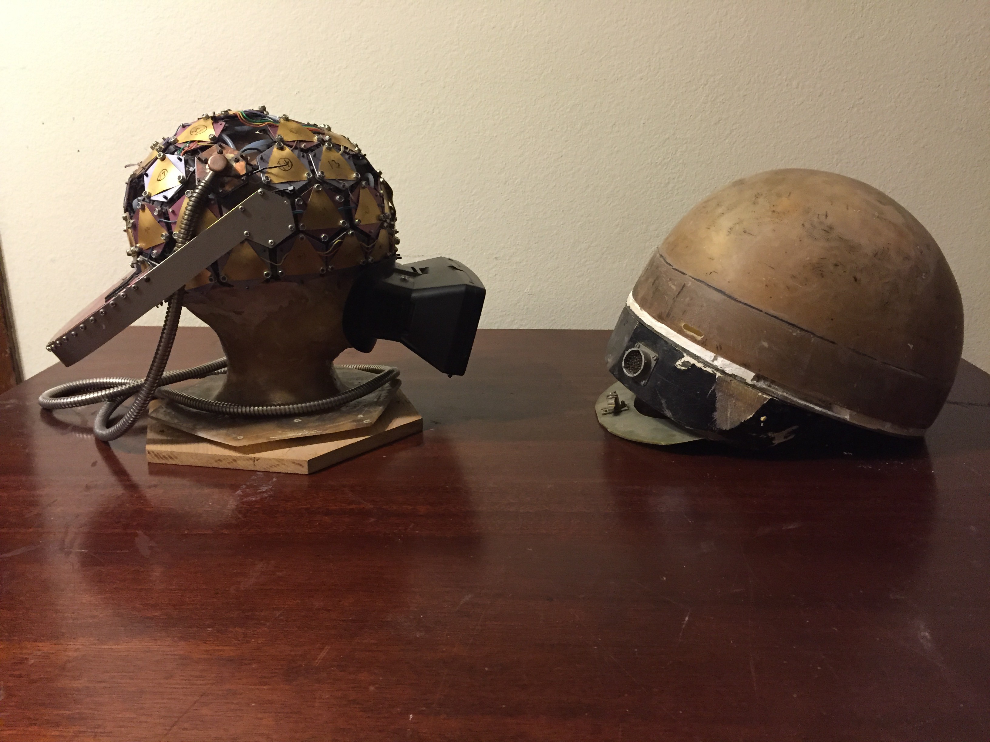
    The Mark-96, circa 1996, on the left illustrates some of the concepts. Although significantly lighter than the Mark-70 circa 1970, it is still far to heavy, As it turns out, keeping the instrument light is the single most difficult design challenge.

    In the present day Mark-16 7 channels are present for each of the hexagonal shapes as shown in the helmet on the left. All told, that sets the present channel count at approximately 350 for the head.

    For matters of economics, the system is partitioned into groups of 7. For each group there is a signal node defined by an Xilinx Artix XC7A35T and a PIC32 MZ processor. Further on down the signal processing chain is a Xynq FPGA running Linux, 802.11 wireless interface, Bluetooth. In all cases the connectivity between the various blocks that make up the system are via the Cyince interface, or via USB3.1-C ports. If a Tunderbolt 3 interface is available the a data rate up to 40 Gb/s may be enjoyed.

View all 7 project logs

Enjoy this project?

Share

Discussions

Similar Projects

Does this project spark your interest?

Become a member to follow this project and never miss any updates