Just from probing while I was offline this weekend:
PA5 (Pin 15) is high frequency pulses, sine and carrier.
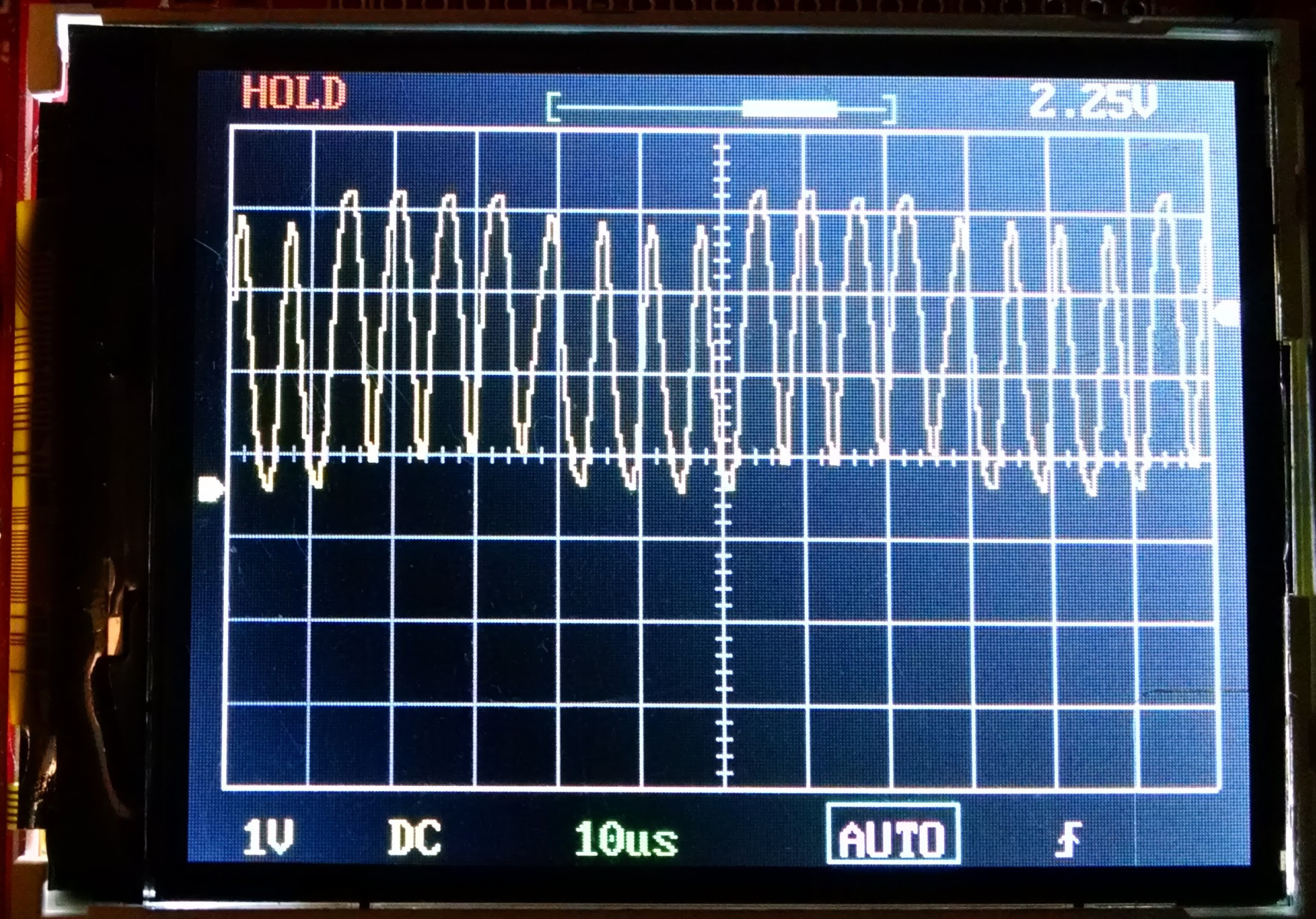
Also on that pin is SPI CLK and ADC_IN 5.
PA8 is giving out a 20 uSec period pulse (500 kHz) when the button is pressed. It's the only one I can see which has MCO as a function but it also does USART1 CLK. I presume this is the MCO output though:
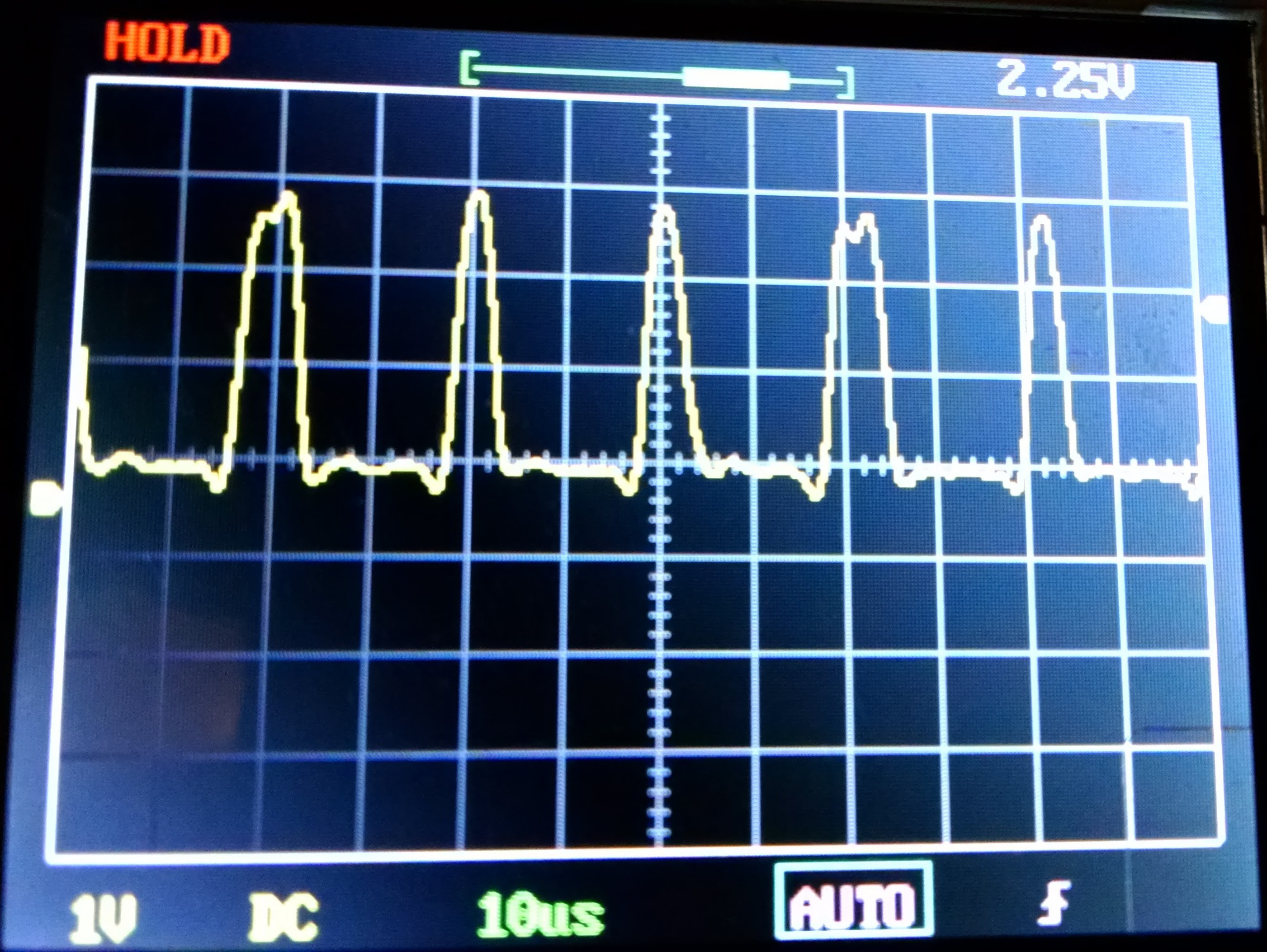
PB7 is giving a short 20 uSec pulse, 150 uSec pause then 50 uSec pulse. It's SDA for I2C_1:
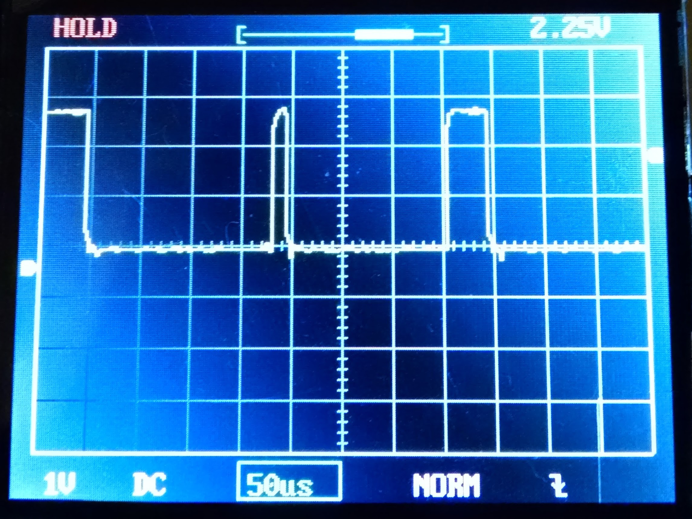
Meanwhile, PB6 is I2C_1 SCL and is producing a 40 uSec period pull down pulse @ 50% duty:
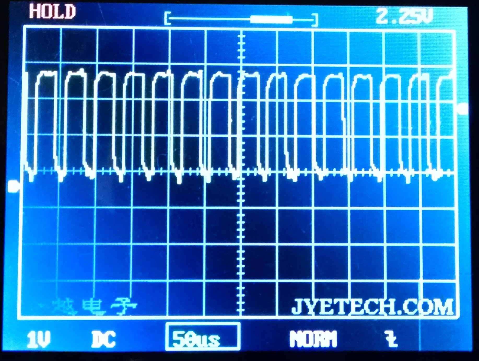
The I2C messes up the LCD when wires got shorted by my probe so I'm confident this is what it's being used for.
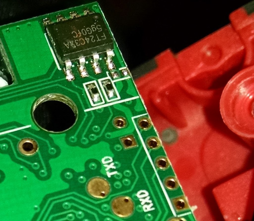
The FT24C32A chip is two wire serial EEPROM. Maybe i2c talking there too?
I have a feeling that the chips near the laser which have 5351 on are copies of the MAXIM 3.3V version of the 535 DAC. More checks required.
I've also emailed SNDWAY, who make the laser module, to see if they'll tell us the inputs/outputs from the module.
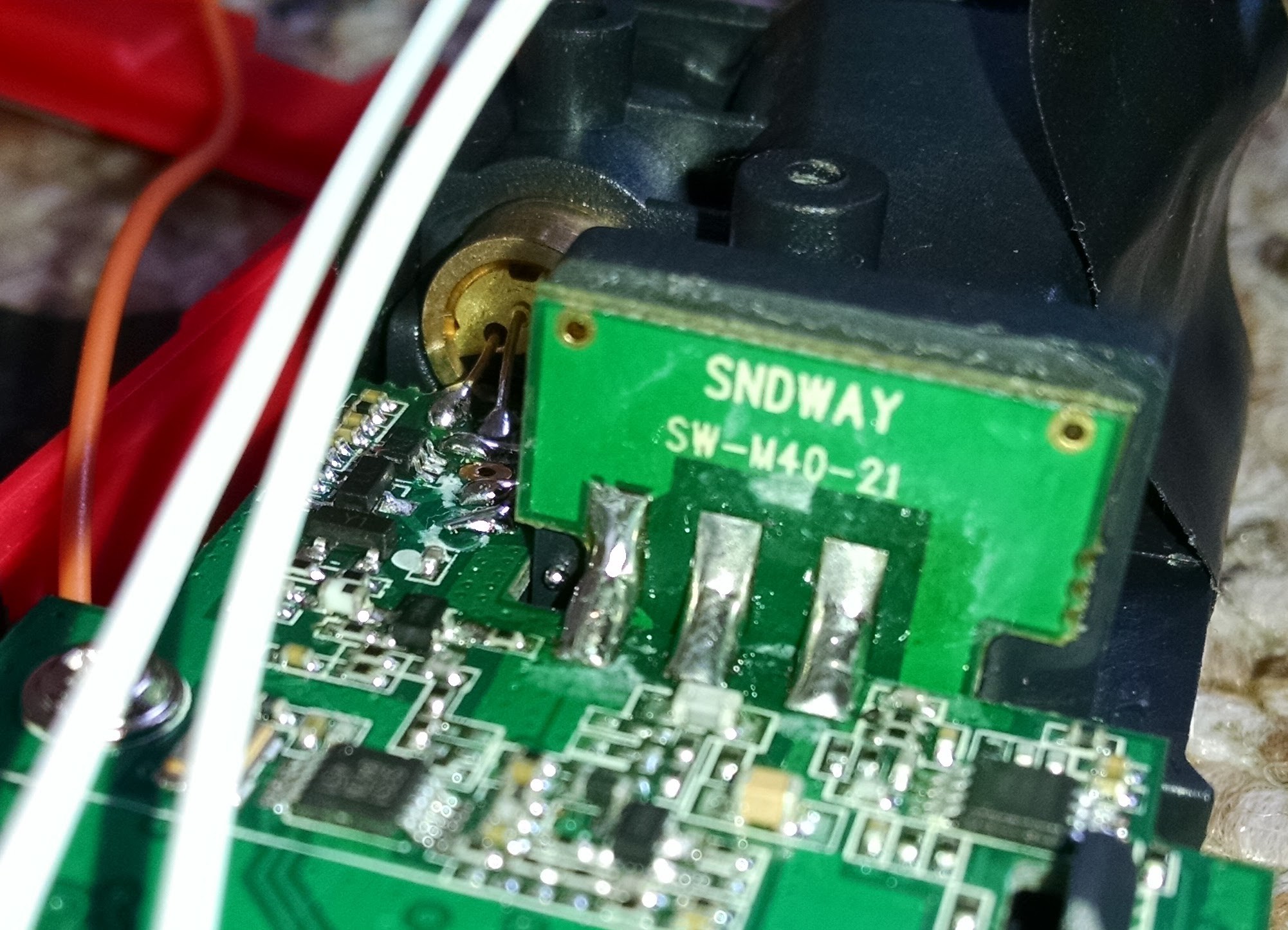
I'm not holding my breath as they also make their own laser range finder consumer products and it would be giving their secret sauce away somewhat.
Please chip in with ideas as I'm about to hit the limits of what I can do with this to get a useful distance measurement out of it!
 Simon Merrett
Discussions
Become a Hackaday.io Member
Create an account to leave a comment. Already have an account? Log In.