 fl@C@
fl@C@

Note: This log entry is a living document. I'll be updating this post to reflect the current configuration as time goes on.. There will also be a log at the end of the post noting modifications to the log, etc..
UPDATED-----> 09.25.2014

This log entry will instruct you on building the beamSplitter Assembly..
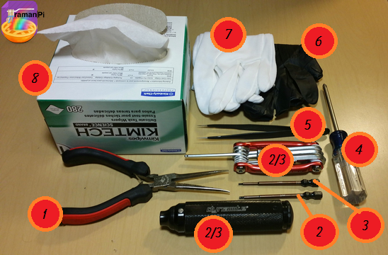
Tools Required:
- 1. Needle Nosed Pliers
- 2. 1.5mm Hex Driver
- 3. 5/64" Hex Driver
- 4. Philips Screwdriver
- 5. ESD Style Precision Tweezers
- 6. Nitrile Gloves
- 7. White Cotton Gloves
- 8. KimTech KimWipes
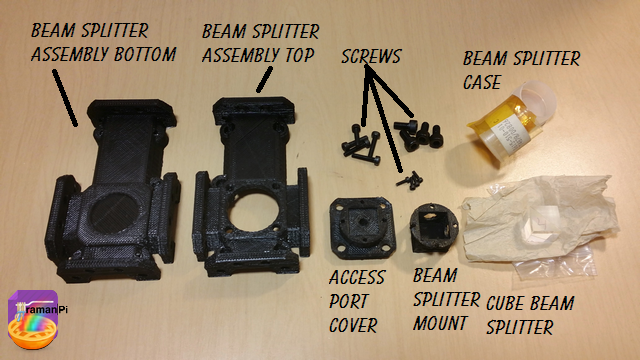
Components Required:
- Printed versions of the following 3D Printed Objects from the gitHub repository:
- (1x) Cube beam splitter 12.5mm for 532nm
- (5x) M2 - 0.45 12.9mm Socket Cap Screws
- (4x) M4 - 16mm Socket Cap Screws
- (4x) M1.6 - 4mm Socket Cap Screws
Steps:
1. Print and clean up the plastic parts. Be sure to use the 3D printed part guidelines. All spurs and supports need to be cleaned as much as possible.
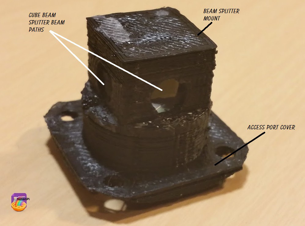
2. Grab the beam splitter, the splitter mount, the access port cover and the 1.6mm screws..
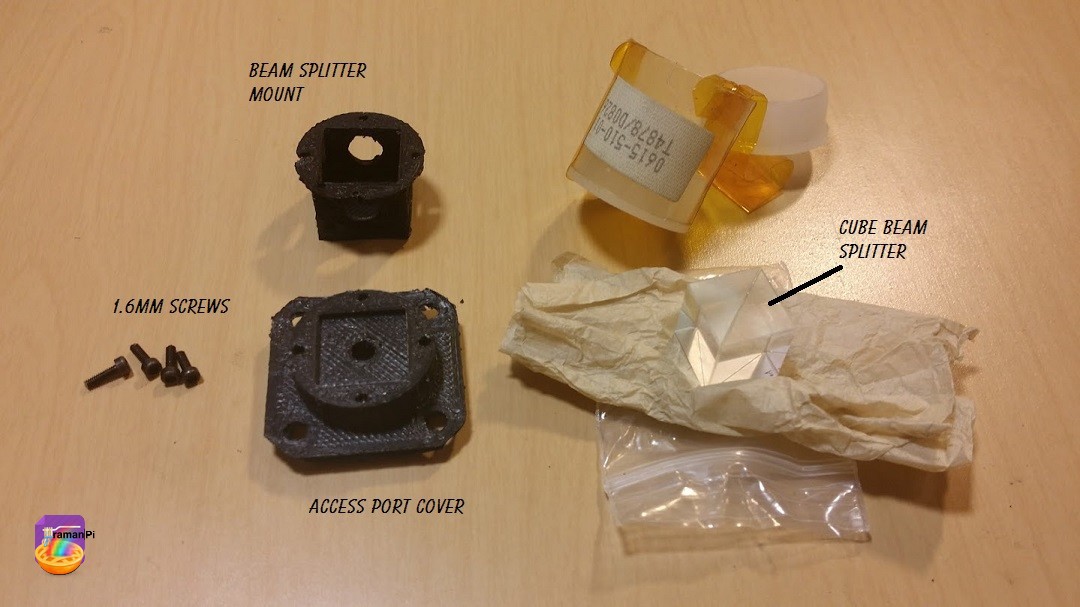
3. While wearing a pair of the nitrile gloves inside a pair of the white cotton gloves, place the cube beam splitter inside the beam splitter mount. Take note of the orientation!
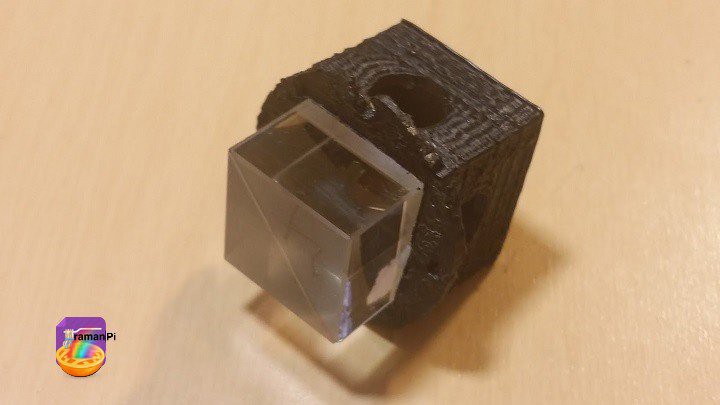
4. You can remove the cotton gloves at this point, but I'd recommend leaving the nitrile gloves on.. Place the beam splitter and mount on bottom side of the access port cover... Make sure you orient the splitter so the angled line is going from the top left to the bottom right from the bottom perspective.
5. Insert 1.6mm screws into mounting holes and tighten down.. Then set aside.
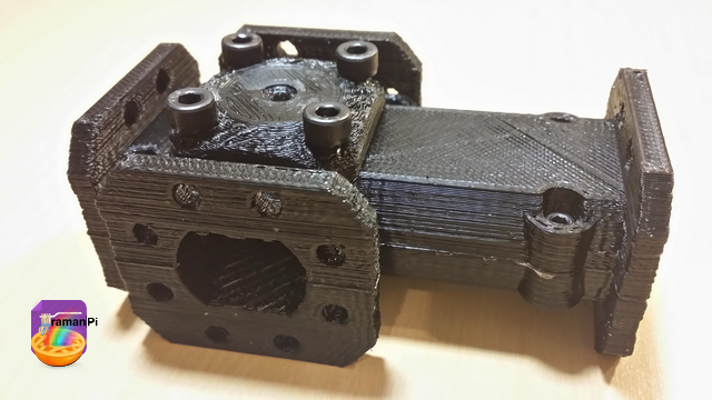
6. Grab the top and bottom half of the beam splitter assembly and 5 of the M2 screws..
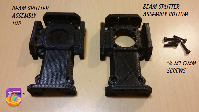
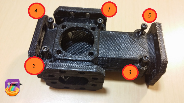
7. Set the top half on the bottom half and place the screws into the holes, then tighten them in the following order.
8. Gather 4 of the M4 screws, the beam splitter in the mount attached to the access port cover.
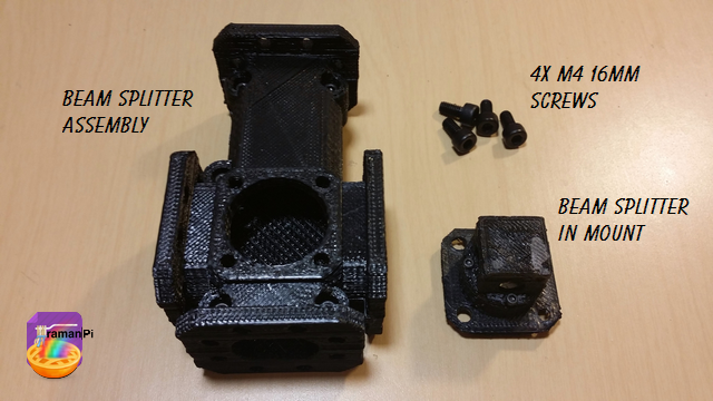
9. Place the beam splitter in its mount attached to the access port cover into the access port making not of orientation. The arrow should be pointing towards the long end of the beam splitter assembly. Place the screws into the holes.
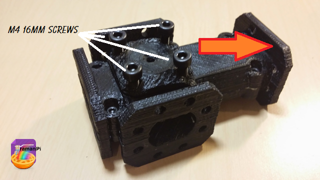
10. Tighten the screws.
That completes the beamSplitter Assembly construction!
Set aside and move to next build!
You can close this tab or return to the build instructions here!

UPDATE LOG:
09.25.2014 - New Entry
Discussions
Become a Hackaday.io Member
Create an account to leave a comment. Already have an account? Log In.
Hi, what's the part number of the beam splitter cube for 532nm? What type of material is that?
Can I use any prism cube?
Are you sure? yes | no
I'm working on refining the design right now... The beam splitter in this design was just a 532nm 12.5mm from eBay.. I am working on finding reliable sources for the kits so I can provide a specific part number soon...
Try emailing me here http://www.meridian-scientific.com/contact.html and I'll answer your questions.. It's getting a little confusing with multiple questions in multiple places.. :)
Are you sure? yes | no
Again for newbie, why do you need a beam splitter? Hoping for a highlevel diagram explain what which part does.
Are you sure? yes | no
I think you'll find the answer here http://hackaday.io/post/2978 that really should answer the question... But here's a diagram of a slightly different design but it gets part of the point across... http://www.sas.upenn.edu/~crulli/spectroscopegrahiccolor.bmp
The beam splitter is fairly central to the operation of the device..
Are you sure? yes | no