 fl@C@
fl@C@

Note: This log entry is a living document. I'll be updating this post to reflect the current configuration as time goes on.. There will also be a log at the end of the post noting modifications to the log, etc..
UPDATED-----> 09.25.2014

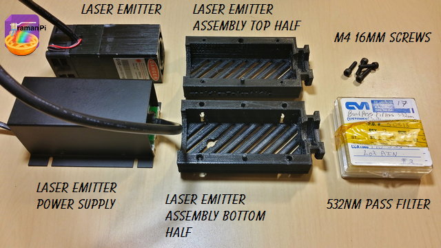
This log entry will instruct you on building the Laser Emitter Assembly..
Tools Required:
- 1. Needle Nosed Pliers
- 2. 1.5mm Hex Driver
- 3. 5/64" Hex Driver
- 4. Philips Screwdriver
- 5. ESD Style Precision Tweezers
- 6. Nitrile Gloves
- 7. White Cotton Gloves
- 8. KimTech KimWipes

Components Required:
- Printed versions of the following 3D Printed Objects from the gitHub repository:
- (1x) 532nm 150mw Green Laser Module with Thermoelectric Cooling and TTL Modulated
- (1x) CVI 532nm bandpass interference filter one inch dia. # F10-532-4
- (4x) M4 - 16mm Socket Cap Screws
Steps:
1. Print and clean up the plastic parts. Be sure to use the 3D printed part guidelines. All spurs and supports need to be cleaned as much as possible.
2. Grab the bottom half of the laser emitter assembly and the 532nm Pass Filter.
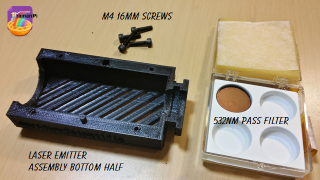
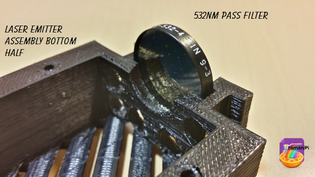
3. Make sure you are wearing the nitrile gloves and a pair of the white gloves over them and place the CVI 532nm bandpass interference filter one inch dia. # F10-532-4 into the bottom half of the laserEmitter Assembly and set aside for the moment..
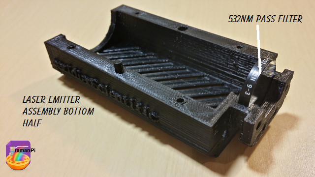
NOTE: Make sure the surface mirror side is on the outside of the assembly!
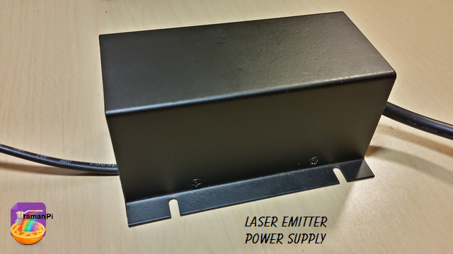
4. Grab the laser emitter power supply.
5. Remove the screws from the cover and remove the cover. Then remove the strain relief screws.
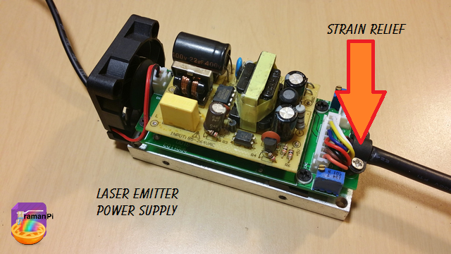
6. Once that is done, remove the laser emitter power cable.
7. Grab the top half of the laser emitter assembly and pass the connector end of the laser emitter power cable through the small hole towards the back from the inside to the outside..
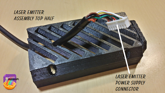
8. Slide the laser emitter assembly top half down the cable and fit the emitter into the assembly.
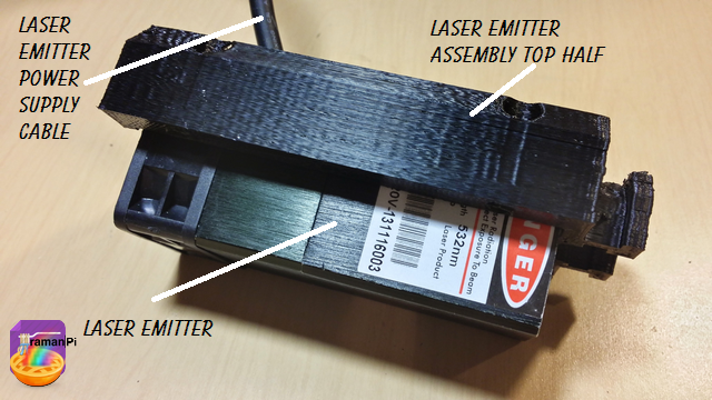
9. Grab the bottom half of the assembly, gently place in on the laser emitter and make sure not to scratch the pass filter! Then place the 4 M4 16mm screws in the screw holes.
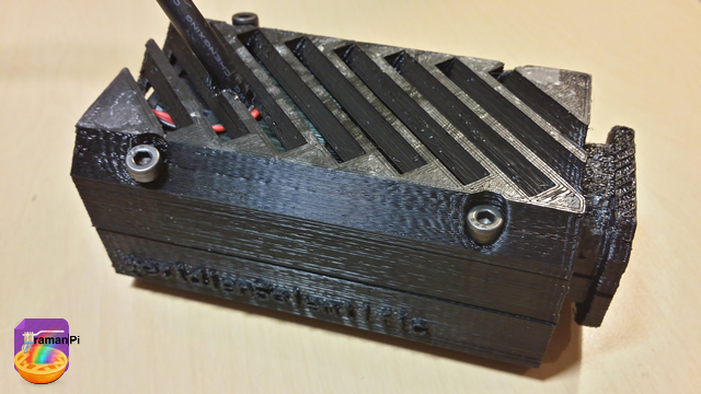
10. Tighten the screws.
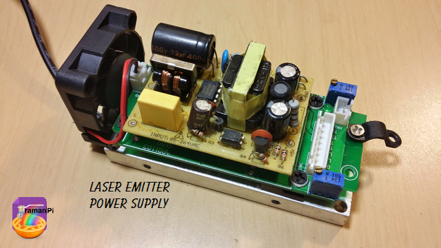
11. Grab the laser emitter power supply, the cover and its screws..
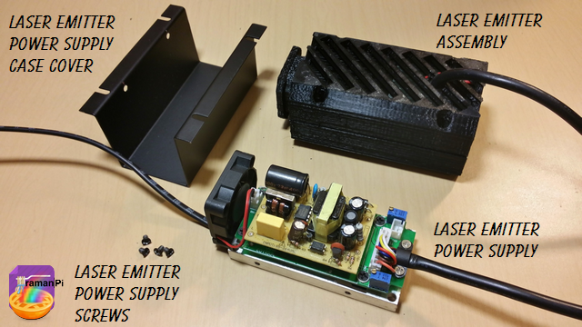
12. Place the cover back on the power supply and screw it on.
And that completes this section! Congratulations!
Set aside and move to next build!
You can close this tab or return to the build instructions here!

UPDATE LOG:
09.25.2014 - New Entry
Discussions
Become a Hackaday.io Member
Create an account to leave a comment. Already have an account? Log In.
https://imagizer.imageshack.us/v2/1110x372q90/912/VR0kNK.png
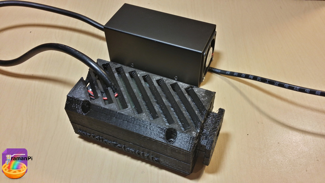
Here's the 532nm laser module with fans and heatsink.
Are you sure? yes | no
I don't see much wrong with that option from a quick look.. I'm starting to look at methods to stabilize/control the temperature and monitor the output as well. Haven't spent a lot of time on it but mostly it will be a peltier acting as a heating/cooling controlled with a pid using a ds18s20.. I haven't worked out the details on how I plan on monitoring/calibrating the laser, but one option might be to feed the laser through the bandpass and into the spectrometer directly (probably with a very tiny entrance slit) to measure the laserline frequency...or into another device...I haven't looked yet but there are some color sensors out there that might work...I just haven't read any datasheets to determine if they are accurate enough in this spectrum... Seems worth a look though..
Are you sure? yes | no
not sure why the laser module needed to be bulky. Do you think type would work? much smaller and cranking out 150mW. https://imagizer.imageshack.us/v2/1025x215q90/661/VAX76P.png
Are you sure? yes | no
Laser line stability is important. Temperature regulation is an important part of that... Thermal mass contributes and a large aluminum heatsink is a good way to facilitate that... Also the power supply makes a good contribution, the laser I chose seemed like a good middle ground between cost and achieving as much a balance as seemed reasonable..
Are you sure? yes | no
Hi, I am a newbie. I think the setup is for advanced user. Like it didn't instruct me why it needs a bandpass filter for green at 532nm? I mean the laser itself is already giving out only 532nm. Maybe adding an IR filter instead. Also Why need a laser module? Why not just a diode green laser at 150mW. it's much smaller and cheaper.
Are you sure? yes | no
Hi.. The 532nm bandpass filter is to filter out everything except the 532nm light from the laser and to make the laserline (the width of the frequency not the beam) as narrow as possible... An IR filter might be an added advantage since some of the less expensive laser diodes produce an IR beat as well from what I understand. But not one instead of the other. The laser used in this design is a green(532nm) diode laser at 150mw.... The purpose for using the version I chose is to ensure there is no variance (as much as possible) in the frequency (532nm)... The entire system is dependent on color... It's a good idea to start of with a value that is known.. :)
For some of the background information you're looking for...such as where I explain why the bandpass is needed check here http://hackaday.io/post/2978 ...
Are you sure? yes | no
thanks, great! I am also wondering why visible violet laser at 430nm not used. it's more powerful and generate better resolution.
Are you sure? yes | no
Hi.. Yes, again it depends on what you want from the system... 430nm laser will more likely produce fluorescence... And that may be desirable, but can also be a major problem..
Are you sure? yes | no