 fl@C@
fl@C@

Note: This log entry is a living document. I'll be updating this post to reflect the current configuration as time goes on.. There will also be a log at the end of the post noting modifications to the log, etc..
UPDATED-----> 10.15.2014

This log entry is where I will keep current information regarding the schematic, board layout and other details about the imagingBoard electronics and firmware.. I will reference this log entry in the 'details' section of the project page.. This log entry will probably change from time to time to reflect the current status of the imagingBoard. If you're interested, it might be worth a bookmark..
The function of the controlBoard is as follows:
- Power Relay for Laser
- TTL Control for Laser
- Monitor Temperature for Laser using DS18B20 sensor
- Control L298 HBridge for Heating/Cooling of peltiers on CCD Array and Cuvette
- PID Monitor and control Cuvette temperature using DS18B20 and L298 HBridge
- Monitor current draw from peltiers on CCD Array and Cuvette using ACS712 current sensor
- Control Beam Shutter using a standard 9gram hobby servo
- Detect Laser Good (verify beam is reaching destination) using a TEMT6000 ambient light sensor
- Open and close Cuvette Tray using stepper motors driven by ULN2003, with optical end stops
- Rotate Filter Wheel Assembly to change from 522nmSP to 550nmLP filters using ULN2003
- Detect Filter Wheel Assembly position using rotary encoder
- Monitor Cuvette Holder for presence of cuvette in tray using a optical proximity sensor
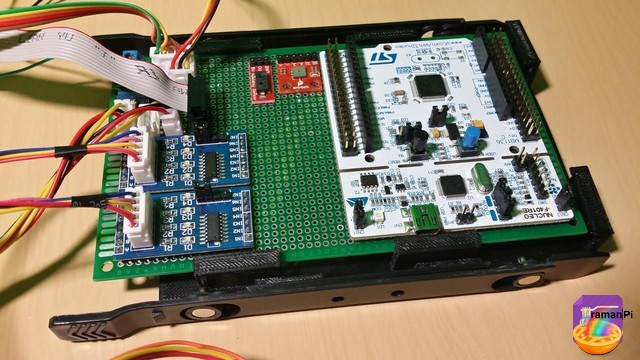
Here is what the current controlBoard looks like..
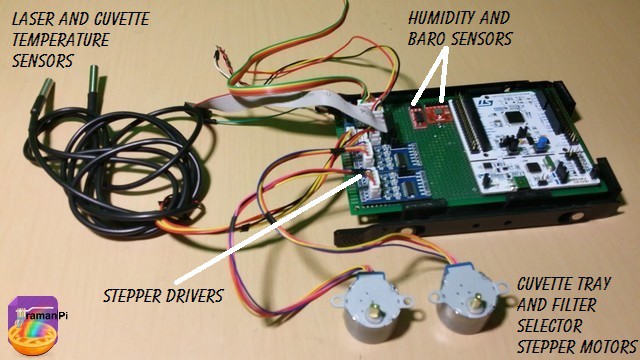
Here it is with the motors and some of the sensors...
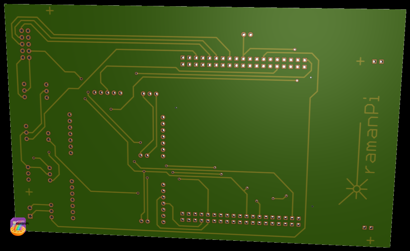
The eagle files are now in the gitHub repository, and here is a rendering of the new PCB layout...
Top
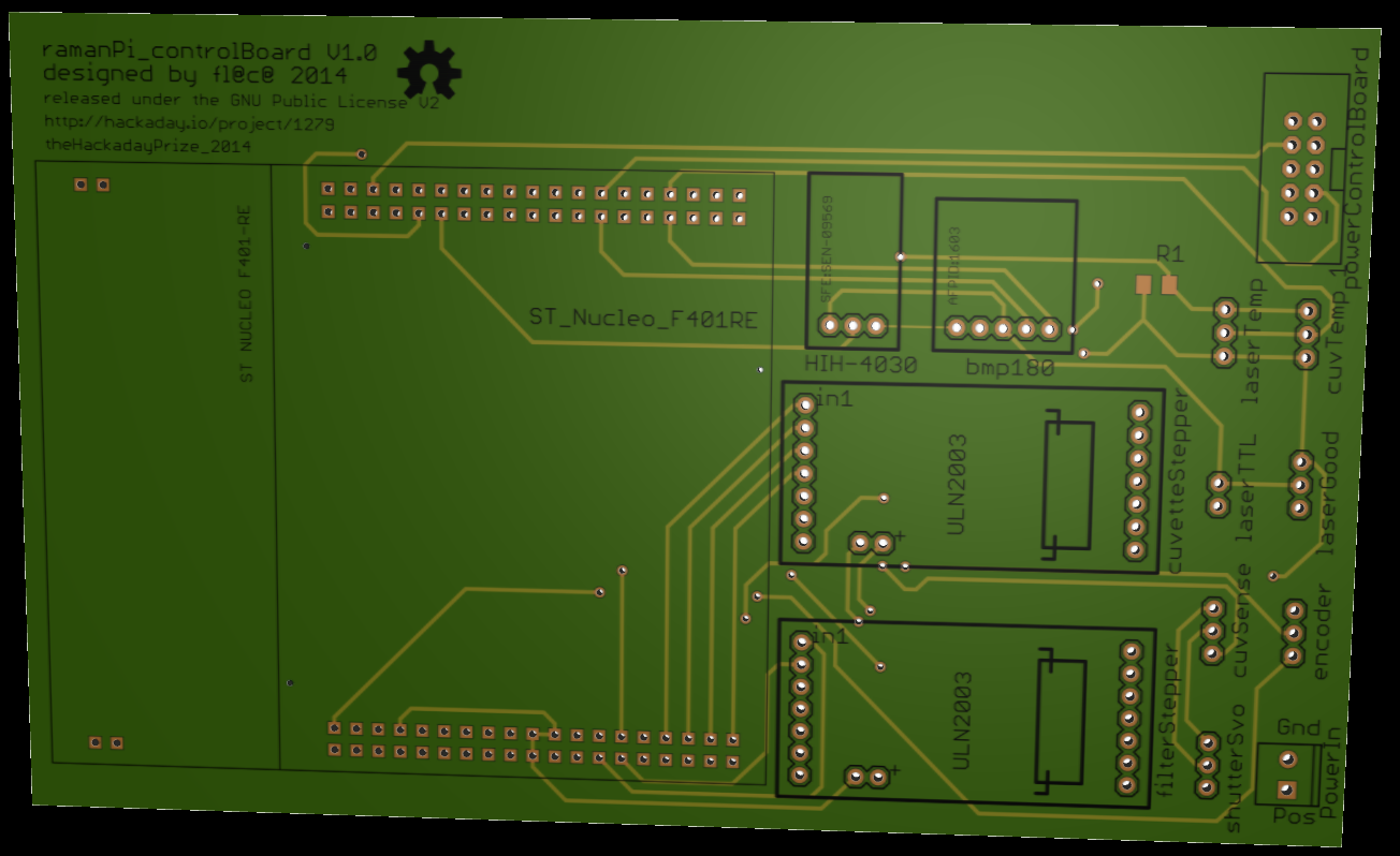
Bottom
Here is the schematic..
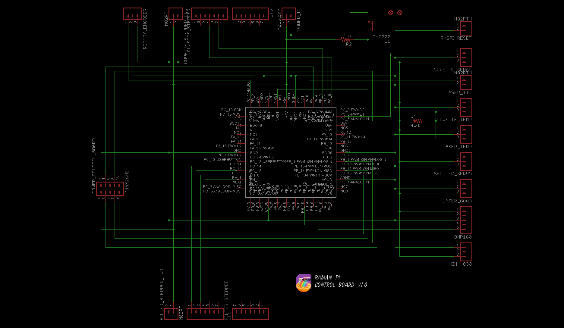
The eagle files, and the firmware are located in the gitHub
- Hardware: gitHub repository
- Firmware: gitHub repository
The board consists of the Nucelo F401RE, two ULN2003 Stepper Motor Drivers, a BMP180 Barometric Pressure Sensor and an HIH-4030 Humidity Sensor..

UPDATE LOG:
09.17.2014 - Added living document info
10.08.2014 - Updated gitHub repository with new PCB design.. Included .studio files and images
10.08.2014 - Updated schematic and posted new PCB layout rendering
10.15.2014 - Updated schematic and posted new PCB layout rendering
Discussions
Become a Hackaday.io Member
Create an account to leave a comment. Already have an account? Log In.
Hi,
Possible to skip all these control boards and use Pi as the sole controller for the whole thing? Theoretically, it should be doable. This way you don't need some many boards and firmwares.
Are you sure? yes | no
Try emailing me here http://www.meridian-scientific.com/contact.html and I'll answer your questions.. It's getting a little confusing with multiple questions in multiple places.. :)
Are you sure? yes | no
same question ,,, could you please give us the answer here
Are you sure? yes | no
Mohammed Shamallakh - Not really. The Pi cannot perform the imaging, we are moving to an FPGA for that since even the microcontroller is not enough to handle the requirements.. The interface and control board could possibly, but the idea was to keep them modular but current development is heading toward integration of all the boards (except the imaging board) onto one which will reduce costs, etc. The reason the imaging board is remaining separate is due to the fact the spectrometer portion will be able to operate as a stand alone device compatible with a regular ocean optics usb4000. Some people asked why the Pi is involved at all, some ask why the boards are, ultimately choices were made during the contest but hopefully we find a decent balance. Thanks for your interest.!
Are you sure? yes | no