-
1Step 1
![]()
Below is a list of build instruction logs that will instruct you on how to go all the way from sourcing your components to printing the parts, and constructing your very own raman spectrometer!
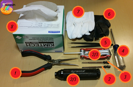
To begin, you will need some tools.. Pretty much every section requires similar tools. If a section requires a special tool not listed here, it will state that and show you which tool is appropriate.
Tools Required:
- 1. Needle Nosed Pliers
- 2. 1.5mm Hex Driver
- 3. 5/16 Hex Driver
- 4. Philips Screw Driver
- 5. Precision Tweezers
- 6. Nitrile Gloves
- 7. Cotton Gloves
- 8. KimTech KimWipes
![]()
3D Printed Part Guidelines:
Printing the 3D Printable parts will take you probably about a week. The spectrometer portion alone took about 15 hours on my XYZ daVinci 1.0 printer.. The 5.25" Drive tray takes about 10, and most of the other parts are about 6 or 8 hours.. Print in high enough quality to make sure the parts end up solid enough that they won't crumble in your hands..use 30-50% density... Supports are a good idea and the spectrometer really should be printed with the inside facing the floor. I managed well with .2mm height, you might want to try .1 or whichever is best for your printer. All the parts have been designed for use with ABS plastic and I would recommend using black ABS filament. For parts with beam paths, I am investigating different ways to coat the interior for reduction in reflections, etc. For now, if you like you can coat them with a flat black paint..this will help keep the noise floor down.
![]()
All of the 3D Printable objects are located in the gitHub repository. They have been created with openSCAD and can be modified, etc. You can view the .STL files and you can download and edit / modify the .SCAD files as well.
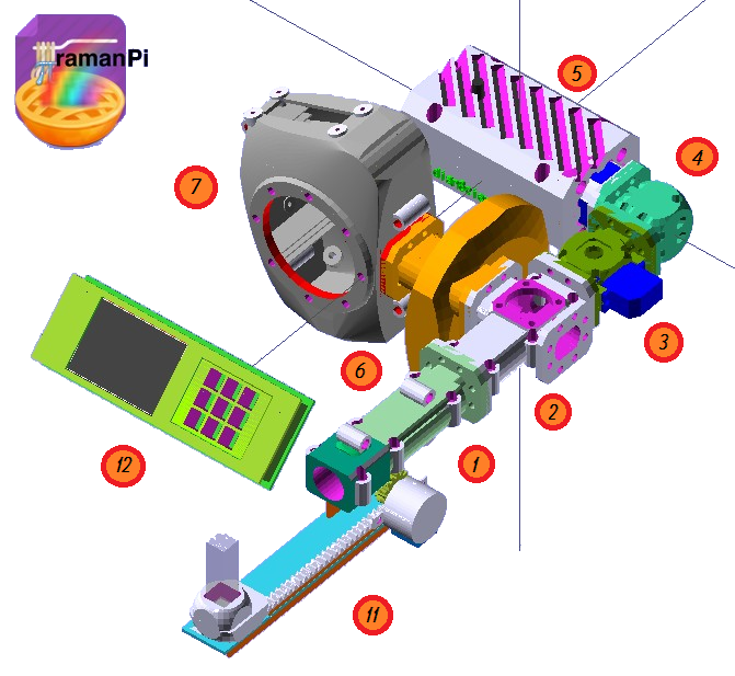
Sections You Will Be Building and Configuring:
- 1. objectiveLens Mount
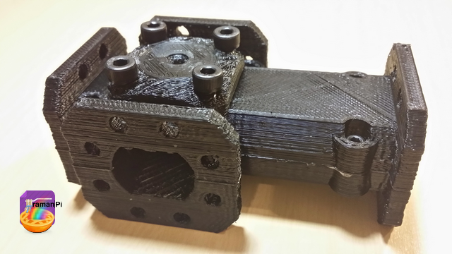
- 2. beamSplitter Assembly
- 3. laserShutter Assembly
- 4. mirrorMount Assembly
- 5. laserEmitter Assembly
- 6. filterSelector Assembly
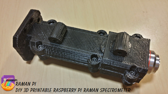
- 7. Spectrometer
- 8. Spectrometer Alignment
- 9. Spectrometer Calibration
- 10. Optical Assembly Construction
- 11. Cuvette Tray Assembly
- 12. TFT LCD and Touch Panel Assembly
- 13. Installing Optics Assembly into ITX Case
- 14. controlBoard Firmware and Supporting Electronics
- 15. powerControlBoard Firmware and Supporting Electronics
- 16. interfaceBoard Firmware and Supporting Electronics
- 17. imagingBoard Firmware and Suporting Electronics
- 18. raspberryPi Interconnections
- 19. raspberryPi Software Configuration
- 20. PC Client Software Configuration
Following Instructions:
Each section of the raman spectrometer system is divided into separate build logs to make it easier to find a section and keep the flow. You'll see each section has a "LET'S BUILD IT" graphic..
You can click on that and it will take you to the appropriate instructional build log associated with that section! At the end of the instructional build log, there will be a link to return here...or you can just close the tab and this tab should be here waiting!
![]()
-
2Step 2
![]()
Section: 1
![]()
A Completed objectiveLens Mount
![]()
Components Required:
- Printed versions of the following 3D Printed Objects from the gitHub repository:
- (1x) 100x Microscope Objective Lens
- (6x) M2 - 0.45 12.9mm Socket Cap Screws
![]()
Click on the graphic above to open a new tab with instructions on how to build your objectiveLens Mount!
![]()
- Printed versions of the following 3D Printed Objects from the gitHub repository:
-
3Step 3
![]()
Section: 2
![]()
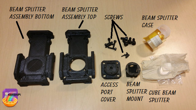
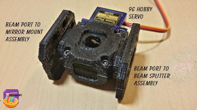
A completed beamSplitter Assembly
![]()
Components Required:
- Printed versions of the following 3D Printed Objects from the gitHub respository:
- (1x) Cube beam splitter 12.5mm for 532nm
- (5x) M2 - 0.45 12.9mm Socket Cap Screws
- (4x) M4 - 16mm Socket Cap Screws
- (4x) M1.6 - 4mm Socket Cap Screws
![]()
Click on the graphic above to open a new tab with instructions on how to build your beamSplitter Assembly!
![]()
- Printed versions of the following 3D Printed Objects from the gitHub respository:
-
4Step 4
![]()
Section: 3
![]()
A completed Laser Shutter Assembly
![]()
Components Required:
- Printed versions of the following 3D Printed Objects from the gitHub respository:
- (1x) mechanical_device_laserShutter_bottom
- (1x) mechanical_device_laserShutter_top
- (1x) mechanical_device_laserShutter_bypass
- (6x) M2 - 0.45 12.9mm Socket Cap Screws
![]()
Click on the graphic above to open a new tab with instructions on how to build your laserShutter Assembly!
![]()
- Printed versions of the following 3D Printed Objects from the gitHub respository:
-
5Step 5
![]()
Section: 4
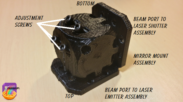
A Complete Mirror Mount Assembly
![]()
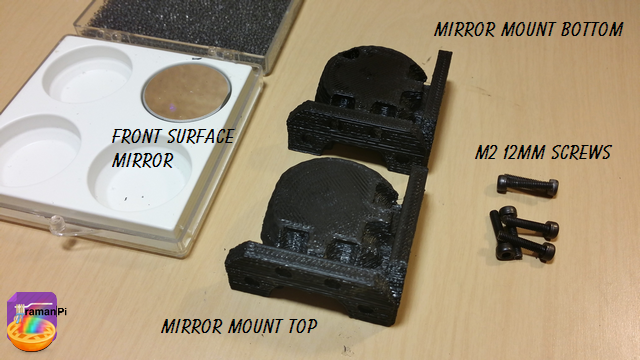
Components Required:
- Printed versions of the following 3D Printed Objects from the gitHub respository:
- (1x) 1 Newport Pyrex First Surface Laser Mirror 1" Model# 10R08 ER1
- (6x) M2 - 0.45 12.9mm Socket Cap Screws
- (4x) M4 -16mm Socket Cap Screws
![]()
Click on the graphic above to open a new tab with instructions on how to build your mirrorMount Assembly!
![]()
- Printed versions of the following 3D Printed Objects from the gitHub respository:
-
6Step 6
![]()
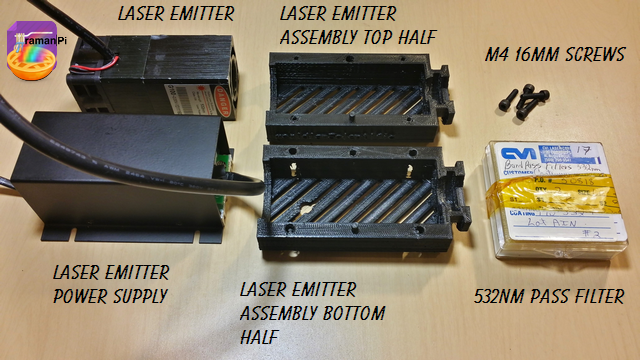
Section: 5
A complete Laser Emitter Assembly
![]()
Components Required:
- Printed versions of the following 3D Printed Objects from the gitHub repository:
- (1x) 532nm 150mw Green Laser Module with Thermoelectric Cooling and TTL Modulated
- (1x) CVI 532nm bandpass interference filter one inch dia. # F10-532-4
- (4x) M4 - 16mm Socket Cap Screws
![]()
Click on the graphic above to open a new tab with instructions on how to build your laserEmitter Assembly!
![]()
- Printed versions of the following 3D Printed Objects from the gitHub repository:
-
7Step 7
![]()
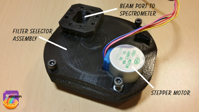
Section: 6
A complete Filter Selector Assembly
![]()
Components Required:
- Printed versions of the following 3D Printed Objects from the gitHub repository:
- mechanical_device_filterSelectorAssembly_front
- mechanical_device_filterSelectorAssembly_back
- mechanical_device_filterSelectorAssembly_filterWheel
- mechanical_device_filterSelectorAssembly_centerHub_Back
- mechanical_device_filterSelectorAssembly_522nmSP_cover
- mechanical_device_filterSelectorAssembly_550nmSP_cover
- (1x) Optical Filter 522SP, 5mm X 40mm X 2.4mm thick
- (1x) Optical Filter, 550LP, 10.1mm dia. X 3mm thick
- (1x) DC 5V Stepper Motor
- (4x) M4 - 16mm Socket Cap Screws
- (8x) M2 - 12mm Socket Cap Screws
![]()
Click on the graphic above to open a new tab with instructions on how to build your filterSelector Assembly!
![]()
- Printed versions of the following 3D Printed Objects from the gitHub repository:
-
8Step 8
![]()
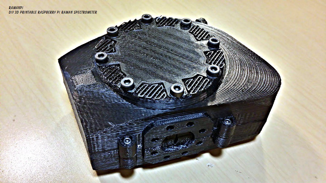
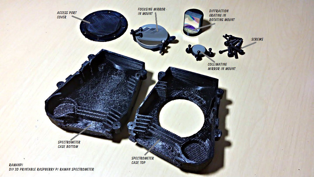
Section: 7
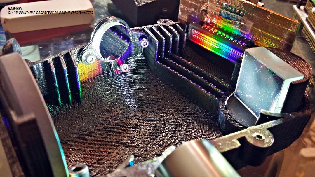
A Completed Spectrometer. A note might be made here that this spectrometer can and will function as an independant device connected to a regular PC running the ramanPi spectraCide software! If you wanted to use it and not build the rest of this project, that's no problem!
![]()
Components Required:
- Printed versions of the following 3D Printed Objects from the gitHub respository:
- (1x) Edmund Optics 1200 Grooves/mm, 25mm Square, VIS Holographic Grating
- Stock No. #43-216
- (1x) Edmund Optics 20mm Dia x 80mm Focal Length, Spherical Mirror
- Stock No. #46-239
- (1x) Edmund Optics 50mm Dia. x 100mm FL Protected Aluminum, Concave Mirror
- Stock No. #43-471
- (1x) Edmund Optics 10μm x 3mm, Mounted, Precision Air Slit
- Stock No. #58-540 (OR EQUIVALENT)
- ramanPi Linear CCD Detector Array Board
- (11x) M2 - 0.45 12.9mm Socket Cap Screws
- (11x) M4 - 16mm Socket Cap Screws
![]()
Click on the graphic above to open a new tab with instructions on how to build your Spectrometer!
- Printed versions of the following 3D Printed Objects from the gitHub respository:
-
9Step 9
![]()
Section: 8
![]()
Components Required:
- Printed versions of the following 3D Printed Objects from the gitHub respository:
- A Completed Spectrometer
- 532nm 5mw Laser Pointer
- Pocket Flashlight
Click on the graphic above to open a new tab with instructions on how to align your Spectrometer!
- Printed versions of the following 3D Printed Objects from the gitHub respository:
-
10Step 10
Section: 9
Spectrometer Calibration has not been written yet.. =P
ramanPi - Raman Spectrometer
The open source 3D Printable Raman Spectrometer using a RaspberryPi and easy to find off the shelf components..
 fl@C@
fl@C@

















Discussions
Become a Hackaday.io Member
Create an account to leave a comment. Already have an account? Log In.
I think it fair to say that this is an incomplete project…. Anyone going to take it up?
Are you sure? yes | no
the itx case is a bitfenix prodigy
Are you sure? yes | no
Is there any update for finding the rest of the instruction sets? I'm in the process of beginning this project and was under the assumption there was at least a complete set of instructions.
Are you sure? yes | no
I am hoping to build one of these units. In looking through the instructions, I noticed a few sections missing. Are there links to the missing instructions elsewhere?
I am especially curious about the connections needed between the electronics and the Raspberry Pi as well as how all of the boards, sensors and the spectrometer connect together and fit in the ITX case.
Thank you!
Are you sure? yes | no