fl@C@
fl@C@-
The RGB LED Indicator Ring
07/30/2014 at 03:51 • 0 comments![]()
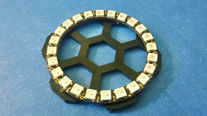
So, as a bit of feedback and just a nice finishing touch...I decided to include a NeoPixel RGB LED Ring from Adafruit inside the case fascia interior that will rotate, etc. during imaging and other processes...
With my current process, it requires a minor modification to the inside of the fascia...
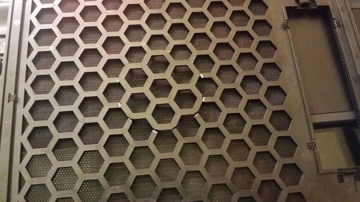
You start off by sitting the LED ring in the middle of the inside and mark off the cut...
![]()
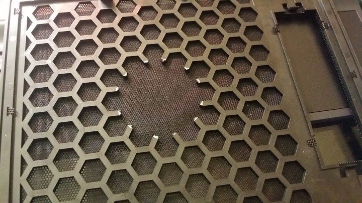
Then make the cut...
![]()
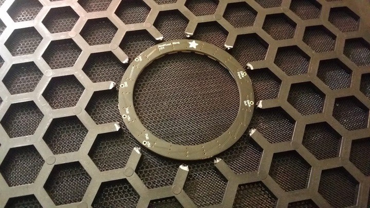
Verify the LED ring fits...
![]()
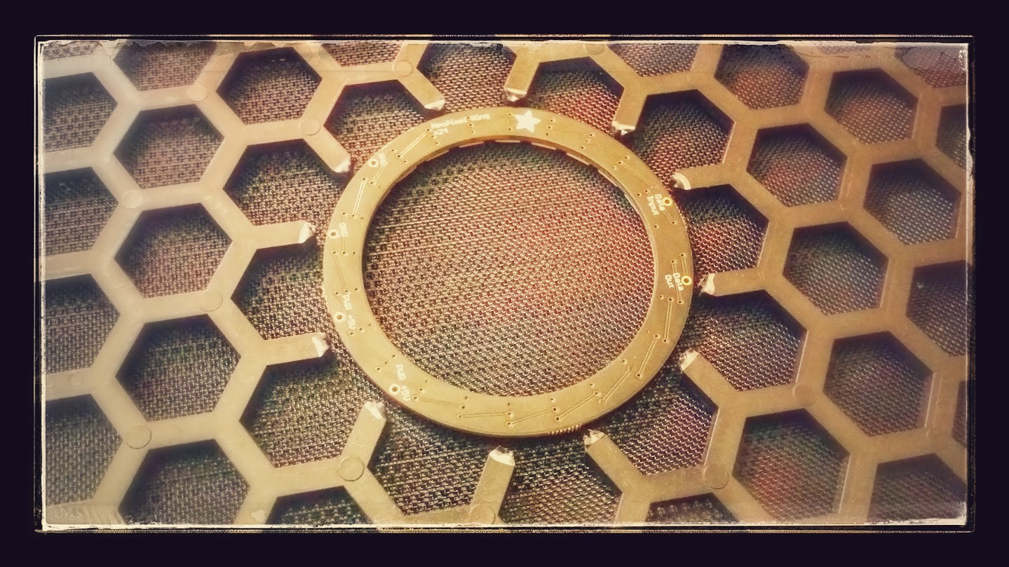
It's kinda artsy even...or..have I just been up too late...
![]()
Then we place the LED ring on the portion we cut out... (right now I've double sided taped it..) I will be designing a 3D printable part to adapt this so it fits nicely...
![]()
Here's the ring from the back...
![]()
From the back and mostly what it will look like when installed... Of course there's 3 wires.. etc..
![]()
It lights up! The ring is driven by an Arduino Pro Mini since the library is available, the processor is only $3 on eBay and it's beneficial to offload the task to a smaller mcu.. The pro mini is connected to the interfaceBoard via serial and is sent commands for different sequences, etc. on demand..
![]()
![]()
![]()
-
Doing more than one thing at a time.....
07/23/2014 at 06:42 • 0 commentsSo.. I've been meaning to give an update that shows a little history and some of my failures and what I did to get past them so far... I'm still working on that.. :)
I'm doing this update to show a bit to round the edges on what I have been doing...in the past few days..
As the previous couple posts show, I've been working on getting serial communications going.. I think I'm pretty satisfied with what I have.. It pretty much worked from the start, and there doesn't seem to be any packet loss....It could use some better handshaking and error correction, but that will come in time..
So, currently.. I just got everything running from the mini-itx power supply.. the power supply plugs into a mini-itx connector on the power controlBoard and it passes the 5v to the controlBoard, interfaceBoard, and the raspberryPi, etc.. I'll put some pictures up as possible..
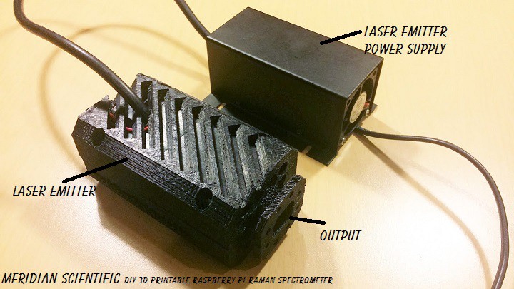
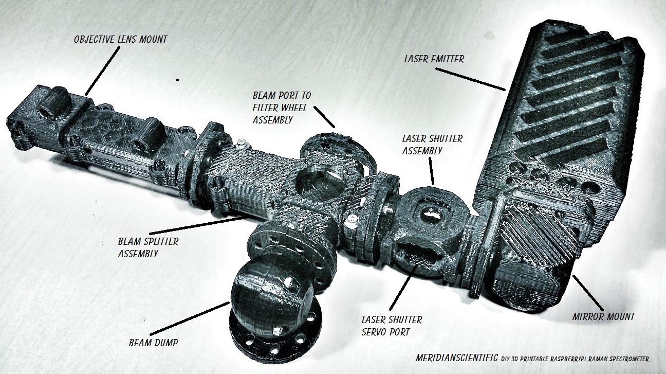
In the meantime, here's a couple pictures of the laser emitter and power supply.. with the emitter seated into it's nice little case/mount...
![]()
A view with the bottom half of the case removed....
![]()
And a rear view showing the cooling fan...
![]()
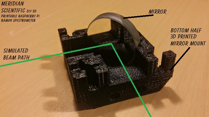
Here is a couple pictures of the mirror mount that bolts to the face of the laser emitter...
Bottom half with mirror in place and simulated beam path...
![]()
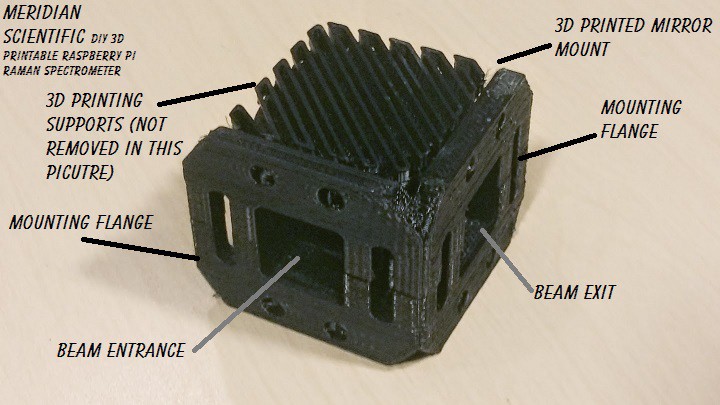
The whole unit.. The printing supports have not been removed in this picture... but it doesn't look a whole lot different after they are removed.
![]()
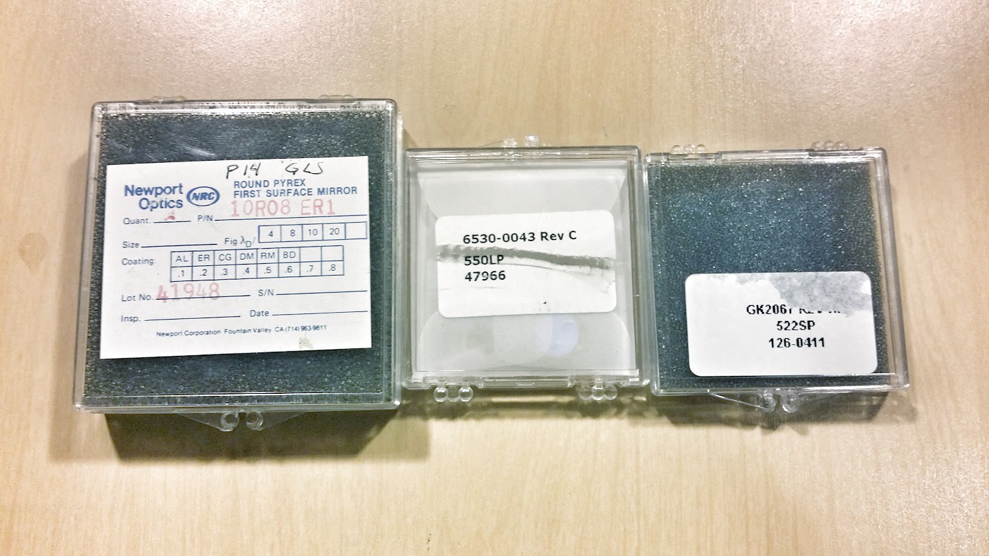
Here is a photo of some of the optics... The important parts...the 522nm Short Pass filter and the 550nm Long Pass filter.. I'll post a photo of the actual filters soon.. I didn't have the gloves, etc. ready to remove them safely.. The other on the left is the surface mirror..which is in the image above...These all came from eBay.
![]()
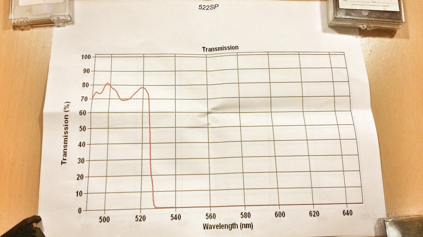
The transmission graph for the 522nm Short Pass Filter..
![]()
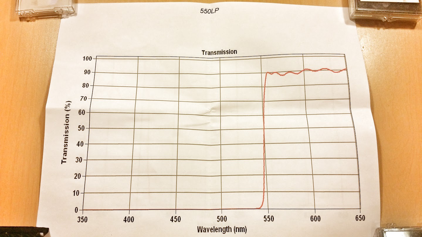
The transmission graph for the 550nm Long Pass Filter..
![]()
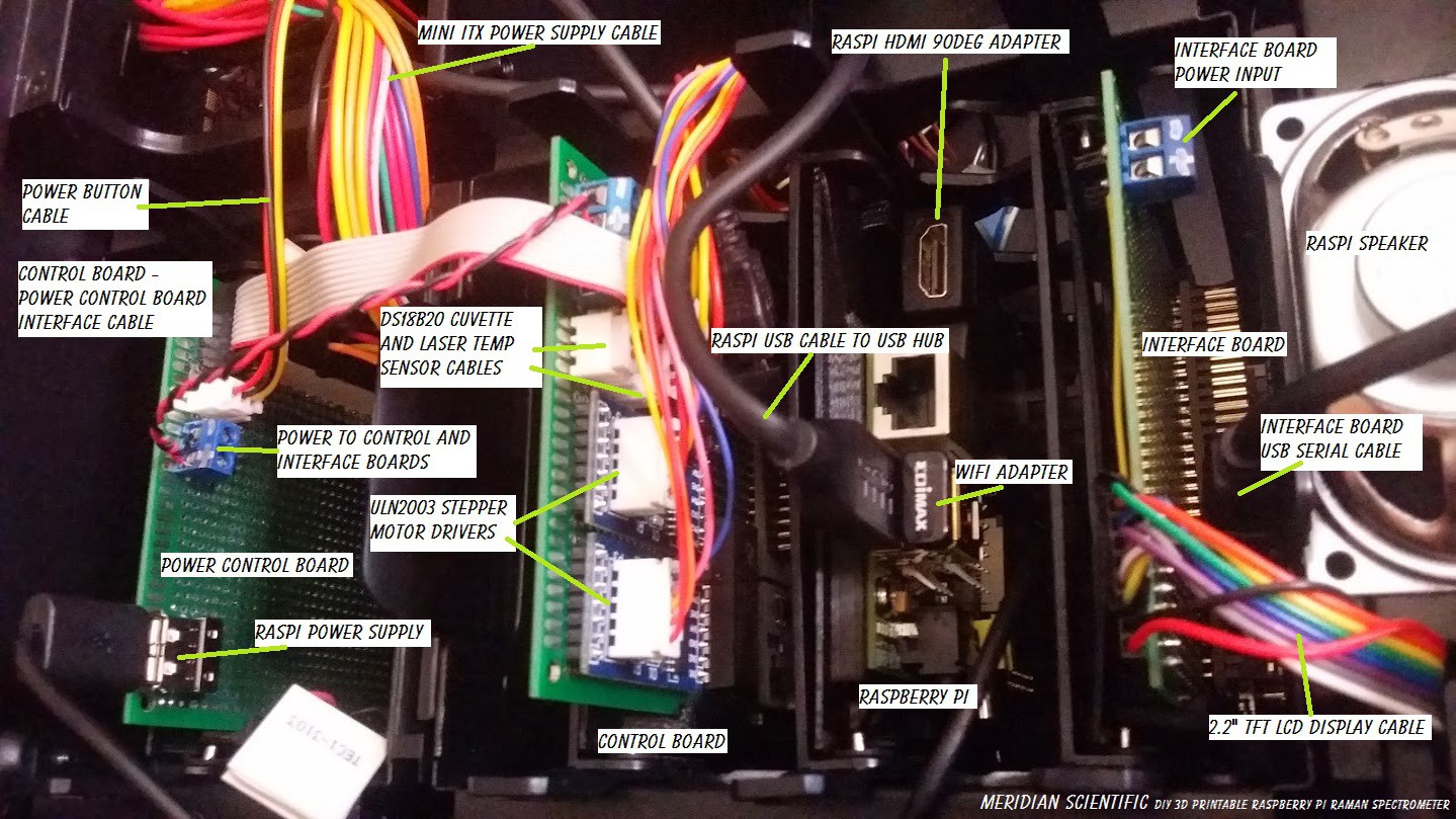
And a quick photo of all of the boards in the case hooked up..
![]()
So far....I have all of the boards (raspi, controlBoard, powerControlBoard, and interfaceBoard) running from the mini-ITX power supply... the raspi is running some test python code that cycles through a loop and sends commands to the controlBoard to move the cuvette tray back and forth, select the filter both with the stepper motors... It then cycles the cuvette and laser peltiers using the HBridge.. First it cools one side of the cuvette peltier, then heats it... and then it cools the ccd peltier...then repeats the whole thing.. Works great!
I'm quite happy that the HBridge controlled peltiers worked out so well.. It proves to me that I will be able to maintain the temperature of the cuvette using a PID controller and PWM and the DS18B20 sensors.. All the code is up on gitHub!
-
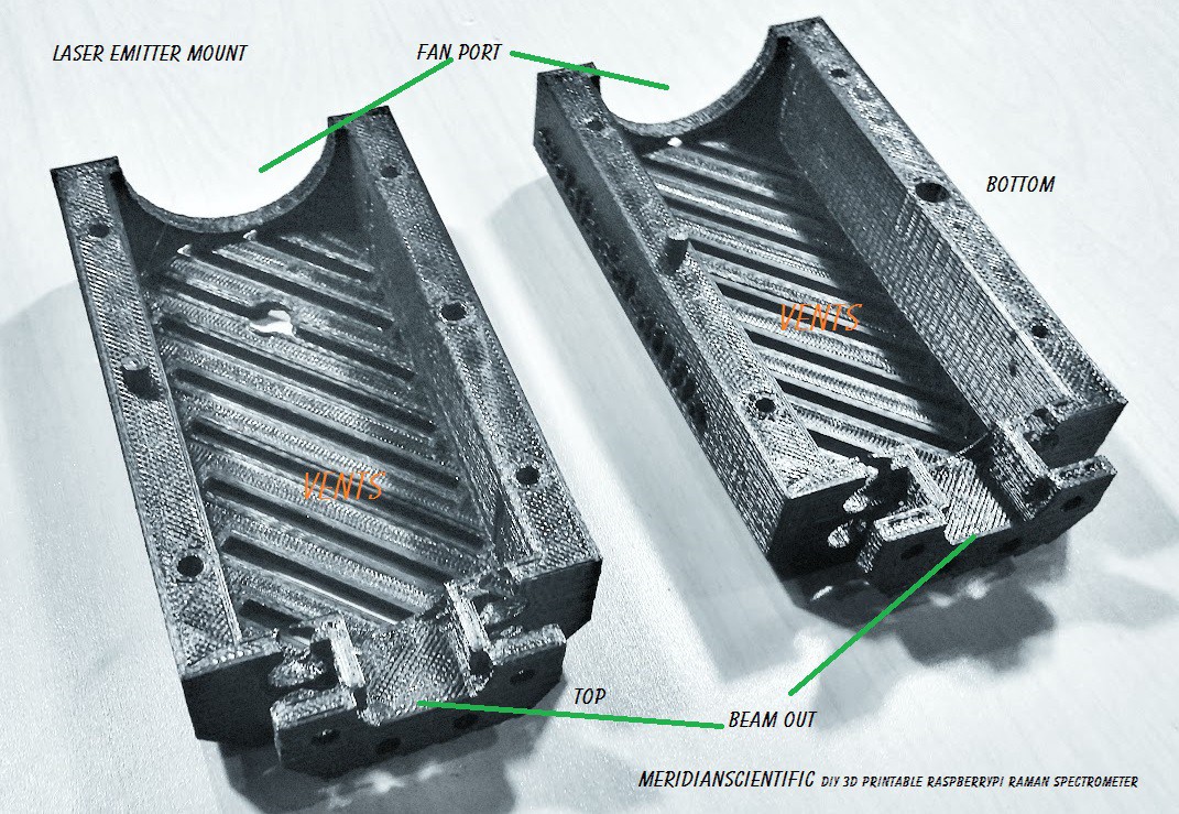
Update on printed parts..
07/22/2014 at 10:46 • 2 commentsI'm still in the design process for some of the printed parts... but here is what I have printed so far...
- 1. Laser Emitter Mount
- 2. Mirror Mount
- 3. Laser Shutter Assembly
- 4. Beam Splitter Assembly
- 5. Beam Dump
- 6. Objective Lens Mount
I'm still designing the filter wheel assembly right now.. and then I will proceed to the rest...and the actual spectrometer... In the mean time, here's some terrible photos... It's apparently very difficult to photograph black plastic.. I'll try some better lighting as soon as I can..
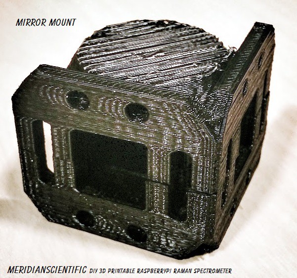
The Mirror Mount
![]()
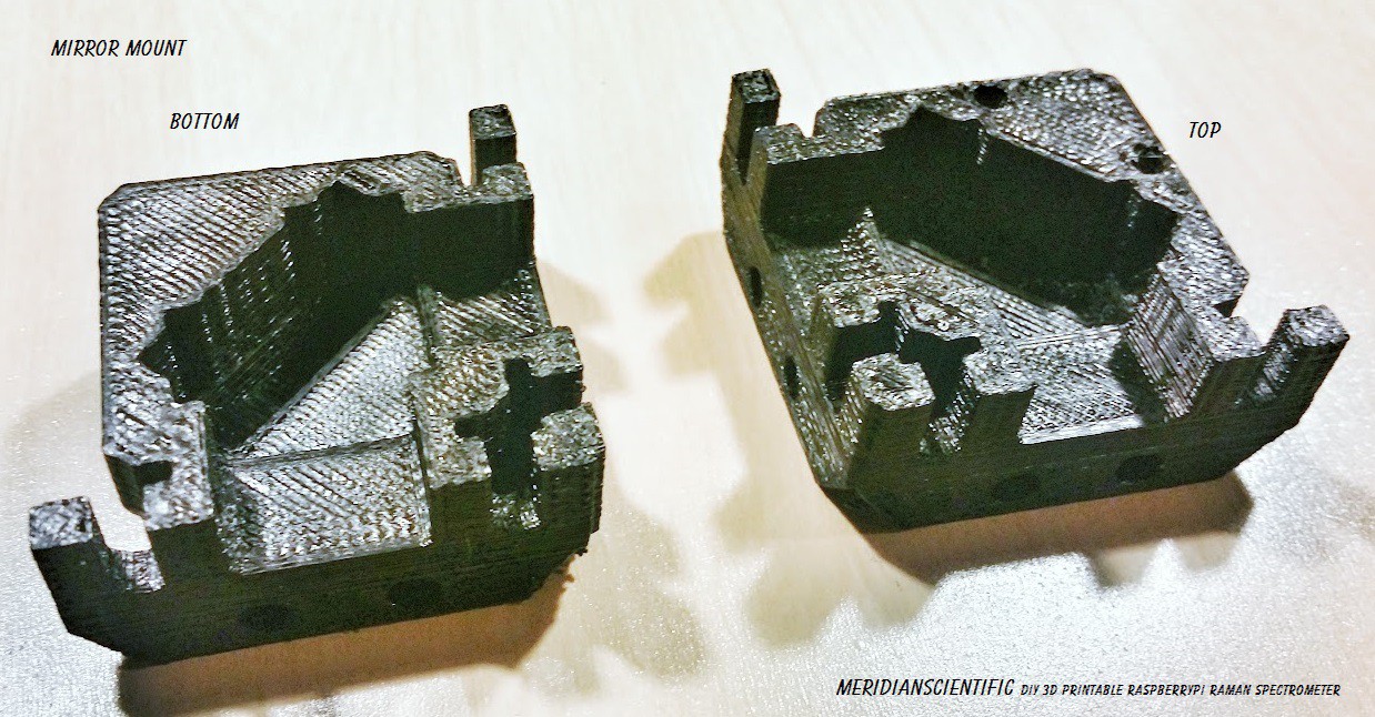
Mirror Mount opened up showing the inside...
![]()
Laser Emitter Mount opened up showing the inside...
![]()
Everything together that I have printed right now.. A similar angle to the rendered shot....
![]()
![]()
-
More serial fun..
07/18/2014 at 07:57 • 0 commentsSo.. I have a pretty good working example going.. As it stands, I have the raspi commanding the controlBoard to check the laser temp, then check the cuvette temp, open the cuvette tray, close the cuvette tray and cycle through moving the filter wheel one rotation forward and then back...looping over and over just as a test...
Some quick pictures...
![]()
![]()
The controlBoard code for the command interpretation goes like this....(I couldn't fit this well using text)
![]()
The functional python (raspi) side is as follows....
![]()
and the command table looks like this...
![]()
Basically, the raspi builds a command like the following req_laser_temp command...
req_laser_temp = (chr(0xF0)+chr(0xF2)+chr(0XC0)+chr(0xC5)+chr(0xF2)+chr(0xF3))
Which is:
[0xF0] [0xF2] [0xC0] [0xC5] [0xF2] [0xF3]
or translated:
[packet_start] [packet_flag] [cmd_laser] [req_laser_temp] [packet_flag] [packet_end]
The controlBoard receives the command through the series of select satements a parses it out...it starts by receiving the packet_start, which moves to the next switch case for packet_flag..it sets the flag and starts a loop...and then moves to the next switch case...it receives the cmd_laser and moves to the next switch case and receives req_laser_temp...it does the temp check and sends the data...then continues in the loop...it receives the packet_flag, and moves to the next switch case and receives the packet_end which drops the flag and out of the loop... waiting for another command..
I haven't added acknowledgments, or much else really.. but this is working pretty solid for the moment..
More tomorrow for sure..! (and of course... all of the code is available on gitHub right now...!)
-
controlBoard functions
07/17/2014 at 09:37 • 0 commentsI've been working on the protocol and list of functions for the controlBoard... I'm trying to establish a command structure and serial protocol for the raspi-boards-raspi communications...
So far, for the control board....I have the following..
Messages will come from the micro to the raspi whenever they're either requested or a condition occurs that merits it.
Commands are sent from the raspi to the micro, they may request a message, or contain arguments that elaborate on the command.
An example might be:
0xFE 0xF0 0xC0 0xC1 0x01 0xFE 0xFF
Which would be [command_laser] [laser_power] [01] or turn the laser on..
The controlBoard should respond with:
0xFE 0xF0 0xF1 0xFE 0xFF
Which would be and acknowledgement..
I don't have this to a science yet, and this is really my first attempt at doing this so formally.. I'm not sure if I'm going to keep the start, end and flags on there or not.. I usually throw something together that works and leave it at that.. but I would like to make this easy for everyone to understand and replicate..
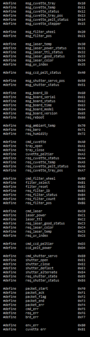
#define     msg_cuvette_tray            0x10
#define     msg_cuvette_temp            0x11
#define     msg_cuvette_status          0x12
#define     msg_cuvette_tray_pos        0x13
#define     msg_cuvette_pelt_status     0x14
#define     msg_cuvette_stepper         0x15


#define     msg_filter_wheel            0x20
#define     msg_filter_pos              0x21


#define     msg_laser_temp              0x30
#define     msg_laser_power_status      0x31
#define     msg_laser_ttl_status        0x32
#define     msg_laser_good_status       0x33
#define     msg_laser_color             0x34
#define     msg_uv_index                0x35


#define     msg_ccd_pelt_status         0x40


#define     msg_shutter_servo_pos       0x50
#define     msg_shutter_status          0x51


#define     msg_board_ID                0x60
#define     msg_board_serial            0x61
#define     msg_board_status            0x62
#define     msg_board_time              0x63
#define     msg_board_model             0x64
#define     msg_board_version           0x65
#define     req_reboot                  0x66


#define     msg_ambient_temp            0x70
#define     req_baro                    0x71
#define     req_humidity                0x72


#define     cmd_cuvette                 0xA0
#define     tray_open                   0xA1
#define     tray_close                  0xA2
#define     cuvette_peltier             0xA3
#define     req_cuvette_status          0xA4
#define     req_cuvette_temp            0xA5
#define     req_cuvette_pelt_status     0xA6
#define     req_cuvette_tray_pos        0xA7


#define     cmd_filter_wheel            0xB0
#define     filter_select               0xB1
#define     filter_reset                0xB2
#define     req_filter_ID               0xB3
#define     req_filter_status           0xB4
#define     req_filter_count            0xB5
#define     req_filter_pos              0xB6


#define     cmd_laser                   0xC0
#define     laser_power                 0xC1
#define     laser_ttl                   0xC2
#define     req_laser_good_status       0xC3
#define     req_laser_color             0xC4
#define     req_laser_temp              0xC5
#define     req_uv_index                0xC6


#define     cmd_ccd_peltier             0xD3
#define     ccd_pelt_power              0xD4


#define     cmd_shutter_servo           0xE0
#define     shutter_open                0xE1
#define     shutter_close               0xE2
#define     shutter_deflect             0xE3
#define     shutter_alternate           0xE4
#define     req_shutter_state           0xE5
#define     req_shutter_status          0xE6


#define     packet_start                0xF0
#define     packet_ack                  0xF1
#define     packet_flag                 0xFE
#define     packet_end                  0xFF
-
Serial Protocols...
07/15/2014 at 00:25 • 0 commentsSo, I'm looking into different ways to implement the serial communication protocols between the control board, interface board / (imaging board), and the raspberryPi..
I looked for open source solutions and didn't find much for framing data, etc. over serial.. I found a protocol called COBS (Consistent Overhead Byte Stuffing).. But I don't know how well that will translate to my needs.. It does have libraries for Python and C, which is good.. I won't eliminate it just yet, but I'm leaning toward some info I found at Eli Bendersky's website http://eli.thegreenplace.net/2009/08/12/framing-in-serial-communications/ which covers a lot of good details on framing and flag bytes with byte stuffing..
Each board will have specific functions (obviously) and a set of commands it will understand.. So, for instance...the control board can receive a command to open the cuvette tray.. We'll say that the user decideds to open the cuvette tray from the manual interface using the keypad and touch panel..on the device. The interface board would accept the command from the user, transmit that request to the raspberryPi via rs232 and the raspberryPi will determine the system state, etc.. and issue the appropriate commands to the other modules in the system.. One of those commands might be to ask the controlBoard what the current state of the laser is.. So the raspberryPi would send a sentence to the controlBoard requesting that information... The control board would in turn respond with an acknowledgment, and so on..
I could get really wordy here, but basically it looks like using escape characters as flags on the beginning and ending are good ways to frame the data.. Then you form the packet...
You want something like:
[start] [command] [arg1] [arg2] [end]
What you would end up with is something like:
[wait] [start] [command] [esc] [arg1] [esc] [arg2] [end]
Like I said, I'm starting...to look into this.. I'd love to hear if anyone has any suggestions..
I'll be trying some experiments here very soon..as well as coming up with a list of commands for each board.
-
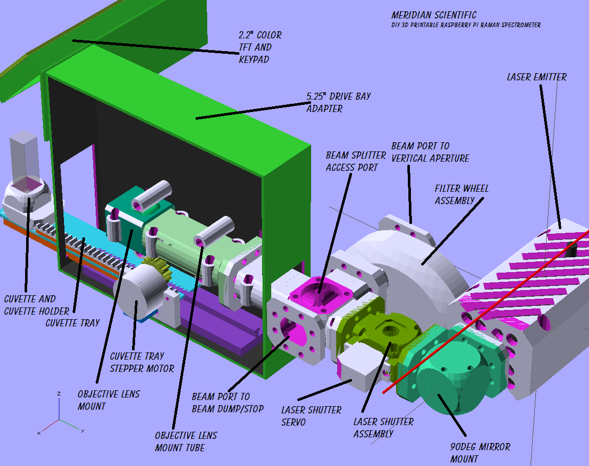
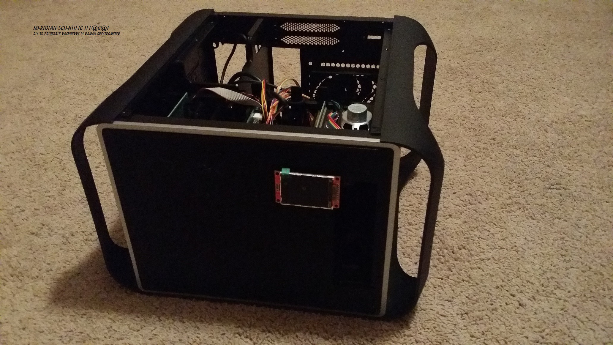
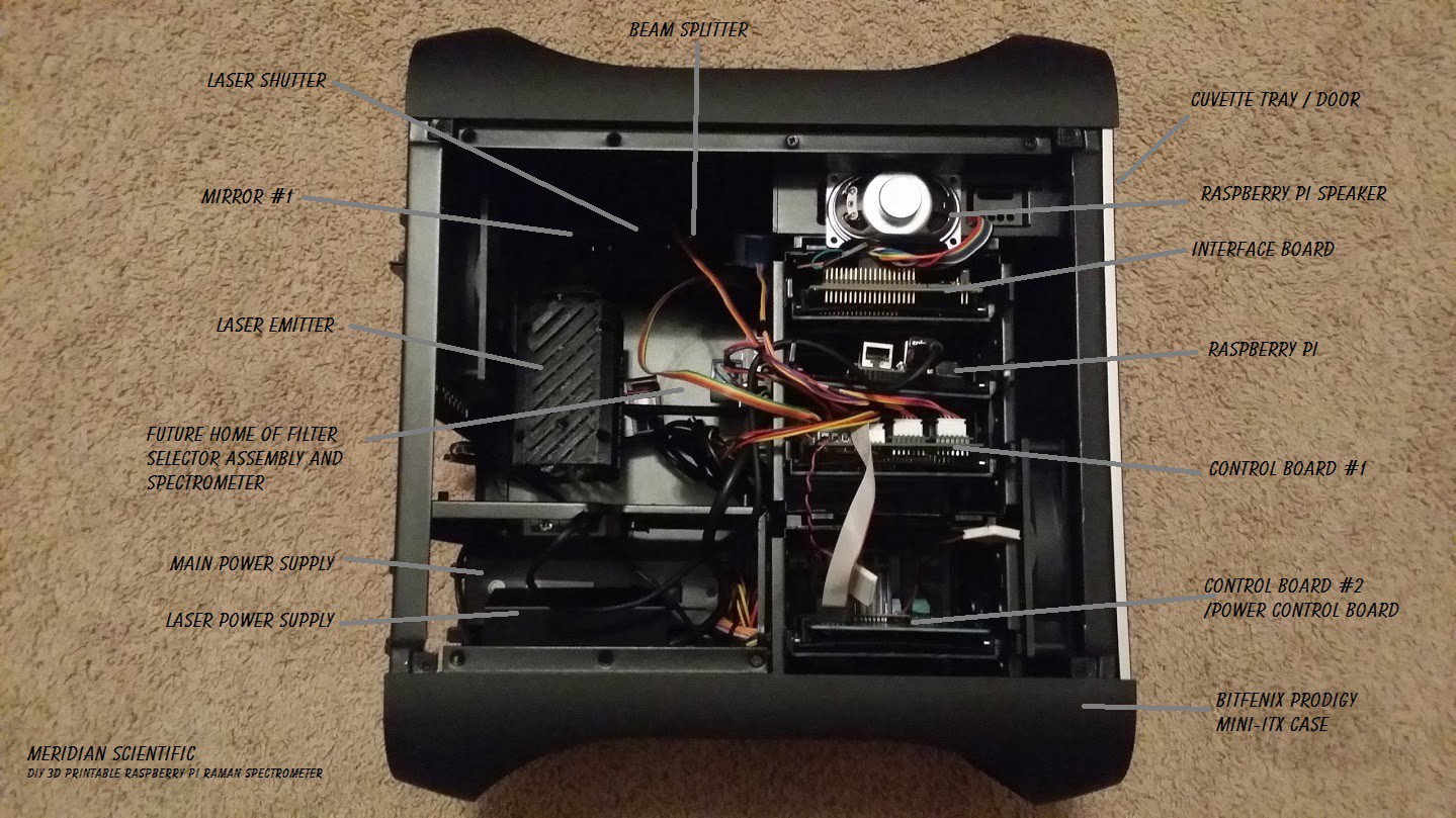
Coming together....
07/13/2014 at 00:32 • 2 commentsHere's the latest shot of the case with the electronics and some of the optics mounted nicely inside... (Nice cable routing will happen later..)
From the front.... The LCD is stuck on with double sided tape for now..
![]()
The inside... It's starting to take shape..!
![]()
-
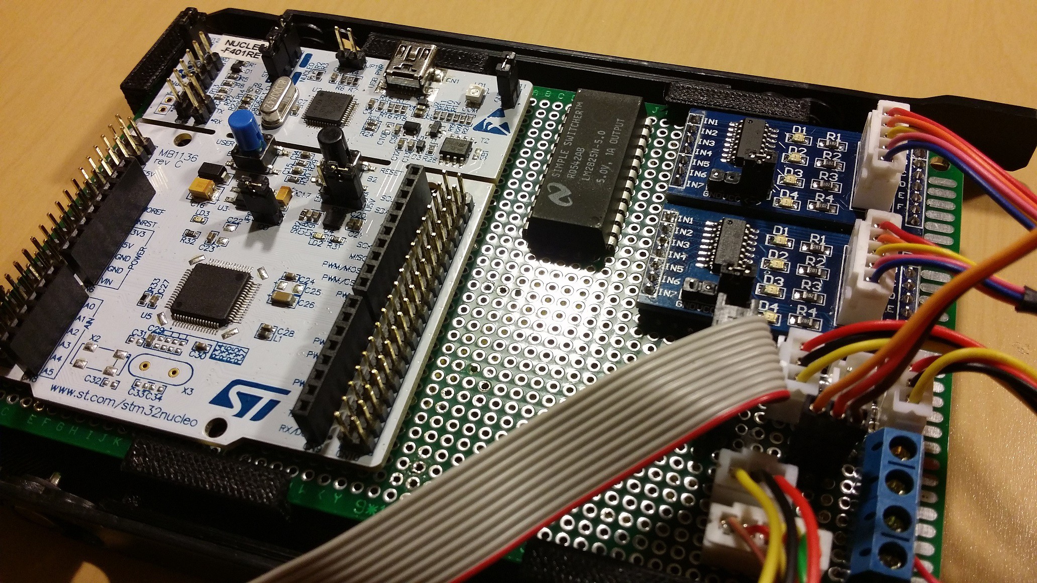
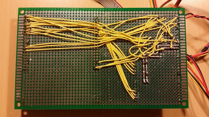
Prototyping PCBs.....oldSchool..
07/12/2014 at 06:51 • 0 commentsSo, I know not too many people do this anymore.. But in an effort to simplify my design stage..I went for hand wiring the boards. Instead of using Eagle first (like I did first)....and then making correction after correction, I'm going back to basics.. and it's working. I pretty much have completed the main controlBoard, and the power controlBoard as well. My patience isn't what it once was, and my soldering on this board wasn't my best by any means..but I'm in a hurry and I'm not making any more excuses.. :)
Here's the main controlBoard from the top...
![]()
Here's an overview of the control board and some of its peripherals..
![]()
Here's the bottom side of the main control board with my ghetto wiring/soldering job...
![]()
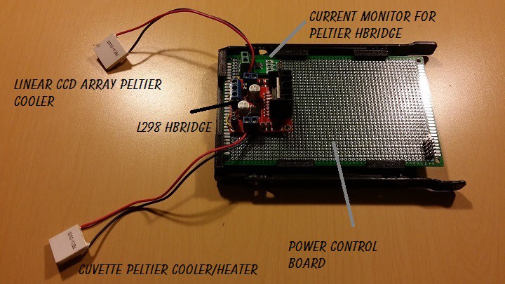
Here is the beginnings of the power control board.. Right now it just has the HBridge and current monitor for the peltiers.. Top view...
![]()
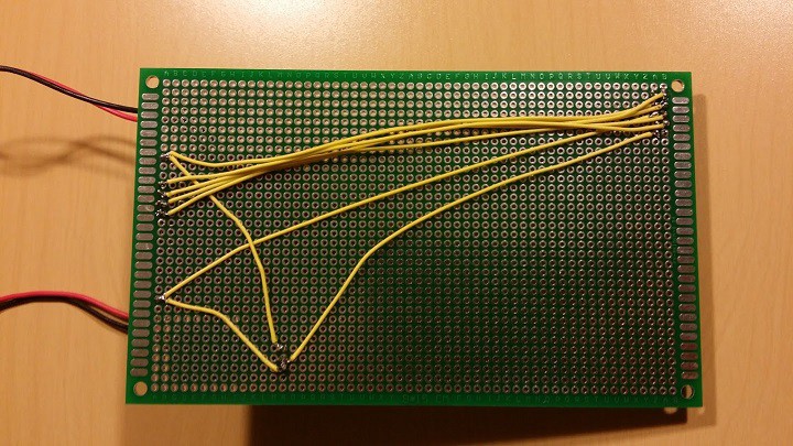
And the bottom view, with it's equally ghetto wiring/soldering job...
![]()
And here are the boards seated in the cage inside the case...along with the raspi, etc..
![]()
As soon as I get these working perfectly, and all the kinks worked out... I'll be doing the design with Eagle..and posting those up on gitHub!
So far I've tested out the stepper motors, the temperature sensors, the servo, and the HBridge Peltier setup... everything checks out fine! I'll be posting some source code up as soon as I get something that's not complete spaghetti.. Also, I will be throwing a schematic up soon... All I have is a hand drawn one right now with a few edits... I'll get that cleaned up and post it as well!
-
A useful video for understanding raman
07/11/2014 at 06:16 • 0 commentsI figured I'd link to this here since they do a pretty good job at describing raman spectrometers..
MustardTree
-
A little perspective from my soapbox....
07/03/2014 at 19:24 • 0 commentsThere's been a lot of talk about simplicity lately... I tend to think this is a slippery slope... It's the old Mac OS vs. Windows argument.. An article Strive for Elegance, Not Simplicity covers much of my opinion on the matter..
Design Justification:
Obviously this isn't a simple device.. There's a lot going on.. You could probably reduce the system to a few filters, lenses, a laser and a cheap spectrometer...but then that is all you end up with..a semi-organized collection of components fashioned into what could be better. My goal with this is to create a piece of equipment that I can use for years to come.. Something that can withstand moving from one side of the room to the other without having to realign the optics and re-calibrate it..something that looks good on my bench and produces an output that I can use. All of this in addition to the stories I hear of how many people have tried to build a raman system and have achieved only mediocre results..which is why I'm guessing there hasn't been an open source raman system out until now. It's not easy and oversimplifying comes at a cost, but thankfully the reward is great when you find a balance.
I explain in fair detail how this system works below, what I don't think I covered was how a normal raman system works.. Without spending a lot of time, they're usually not based on two edge filters like I use..they typically use a notch filter which combines the function of the two edge filters into one..eliminating the need for some of the mechanics, etc. in my system... I decided to go this route because the cost of using a notch filter is far too high for the normal hacker..this adds some complexity, but has to be acceptable otherwise this project would not be worth making open source because too few would be able to build one.
I originally started with a different design (as you can see from the design logs).. That design was my first concept, and seemed logical in its approach as it was modular and was set up much like an optical table.. After much consideration, I decided to go with the more enclosed and rigid structure that you see in the newer pictures and renderings. The older design would work, and probably be ok.. But ambient light, vibration, alignment, adaptability to different optics, mounting, and a few other challenges started stacking against it.. The new design keeps ambient light and reflected laser light out of the picture... It makes alignment easier since it is a rigid tubular structure, only requiring minute adjustments.. It is much easier to adapt to different optics. Mounting the whole structure becomes easier since there are fewer points to have to attach.. Although it may look complex, the whole approach is much simpler to deal with since the parts are simply printed and screwed together. I wanted to find a balance between simplicity, durability, ease of construction, easy to source parts, and a finished looking device that won't fall apart, and require tons of maintenance..
I'd also like to cover something else....
Challenges:
As I mentioned, this isn't a simple device. It is a cross between several disciplines.. There's electronics, programming, optics, mechanical design, chemistry, and maybe a little physics.. A proper raman spectrometer is a very expensive investment.. Trying to bring this down to my goal where a middle school teen can build one and enter it as a science fair exhibit is a moderate challenge.. Designing one that fulfills that desire and will be a useful addition to my bench is another. Obviously, this is the first iteration, and I will probably follow it up with an even better design which is more elegant..but one has to start somewhere...and this is somewhere for me..
So, a major challenge has obviously been the optics.. Deciding on the Crossed Czerny-Turner Configuration was a process..I originally started out with an aberration corrected monochromator grating and was going to use the raspberry pi camera... after some suggestions, investigation, and testing, it looks like the Crossed Czerny-Turner Configuration and a Linear CCD Array are the better option..
Another challenge has been the mechanical layout.. Fitting this system into a mini ITX case was interesting, thank goodness for my linear calipers and openSCAD..
Where it's going from here:
I'm currently working to get prototypes of the PCBs constructed and tested out.. I'm switching between that and getting the filter selection assembly designed..
The PCB design has been a challenge in itself due to the licensing issue with Eagle, and the corruption of the files.. I posted a couple times with designs for the control board, and now I am in the process of redesigning it because I'm apparently overworked or dumb...I didn't stop to think the steppers I used in the design for the cuvette tray and filter assembly are unipolar motors and I designed the circuit using the easyDriver stepper controllers which doesn't like unipolar motors..so I'm switching over to something like the ULN2803.. They use twice the IO pins on the MCU, but shouldn't pose a problem.. I am hand wiring a prototype board before going forward with the Eagle design...this time I'll make sure the bugs are out before proceeding..funny how the simple stuff can get you sometimes..
ramanPi - Raman Spectrometer
The open source 3D Printable Raman Spectrometer using a RaspberryPi and easy to find off the shelf components..