fl@C@
fl@C@-
More on PCBoards
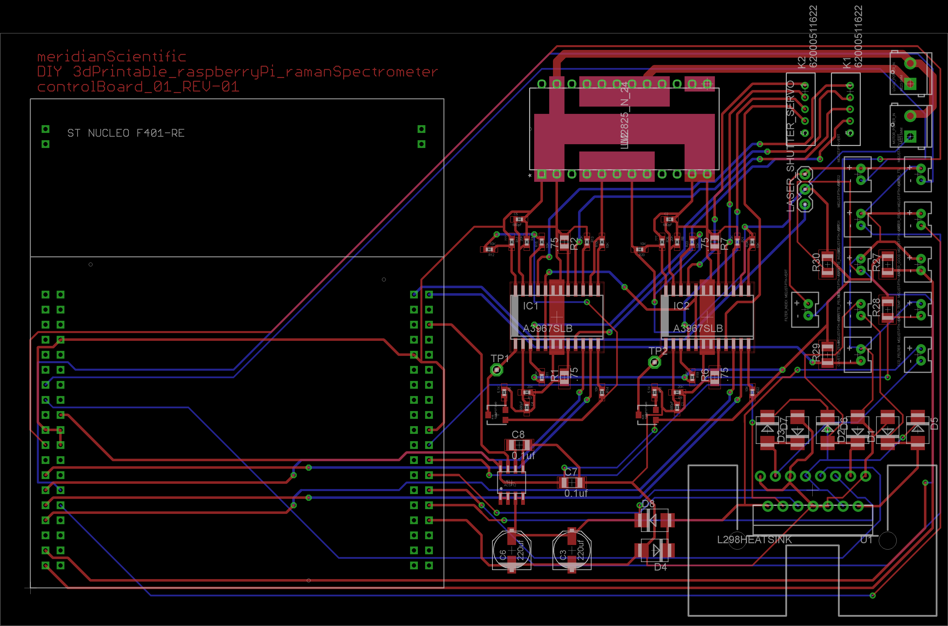
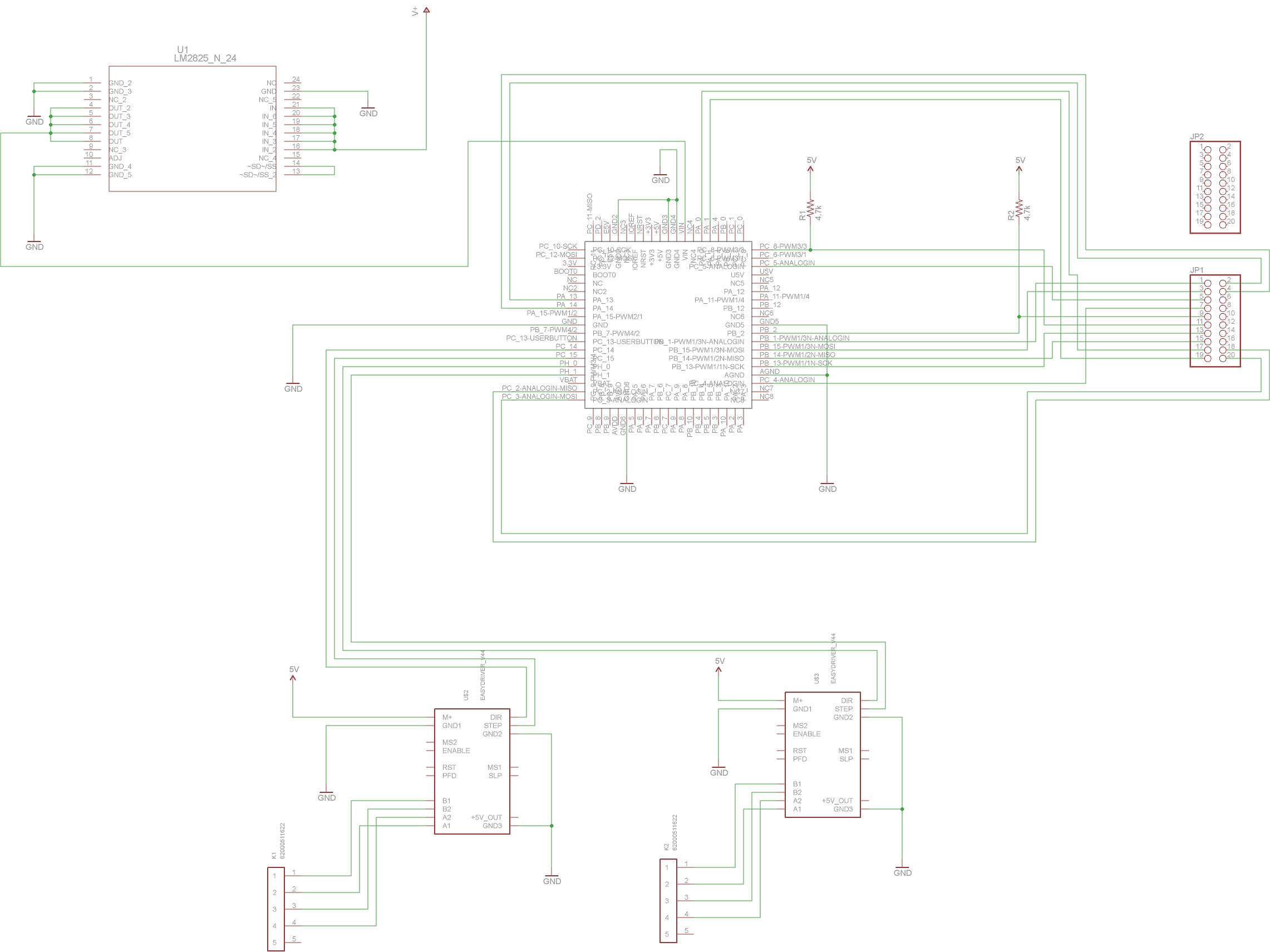
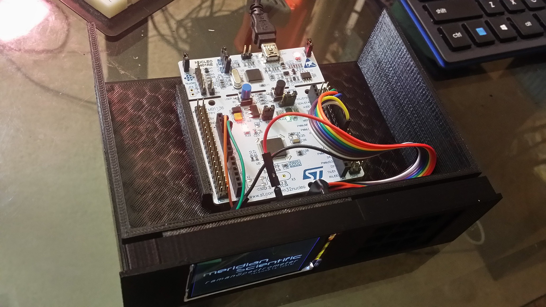
07/02/2014 at 04:29 • 0 commentsI went ahead and purchased an Eagle license so I could do the board layout for the larger PCB size... You might be able to tell from the project logs, I've been having some glitches with these...but all should be on track now... The upgrade seemed to have corrupted the files for the original work I had done so I had to start over....again...(I had tried designSpark on my last attempt)..So here is the start of the control board.. This board is the option to use the Nucleo plugged into the carrier with the rest of the components soldered straight to the board with no breakout boards...
This board is centered around the ST Microelectronics NucleoF401RE.. It contains and does the following:
84MHz ARM Cortex-M4 STM32F401RET6:
2x A3967SLB Stepper Motor Controllers
L298 HBridge
ACS712 Current Monitor
LM2825-5V
- Power Relay for Laser
- TTL Control for Laser
- Monitor Temperature for Laser
- Control HBridge for Heating/Cooling of peltiers on CCD Array and Cuvette
- Montor and control Cuvette temperature
- Monitor current draw from peltiers on CCD Array and Cuvette
- Control Beam Shutter
- Detect Laser Good (verify beam is reaching destination)
- Open and close Cuvette Tray using stepper motors and optical sensors
- Rotate Filter Wheel Assembly to change from 522nmSP to 550nmLP filters
- Detect Filter Wheel Assembly position using rotary encoder
- Monitor Cuvette Holder for presence of cuvette in tray
![]()
![]()
As usual, all the files are up on gitHub... any suggestions are welcome!!!
-
PCBs
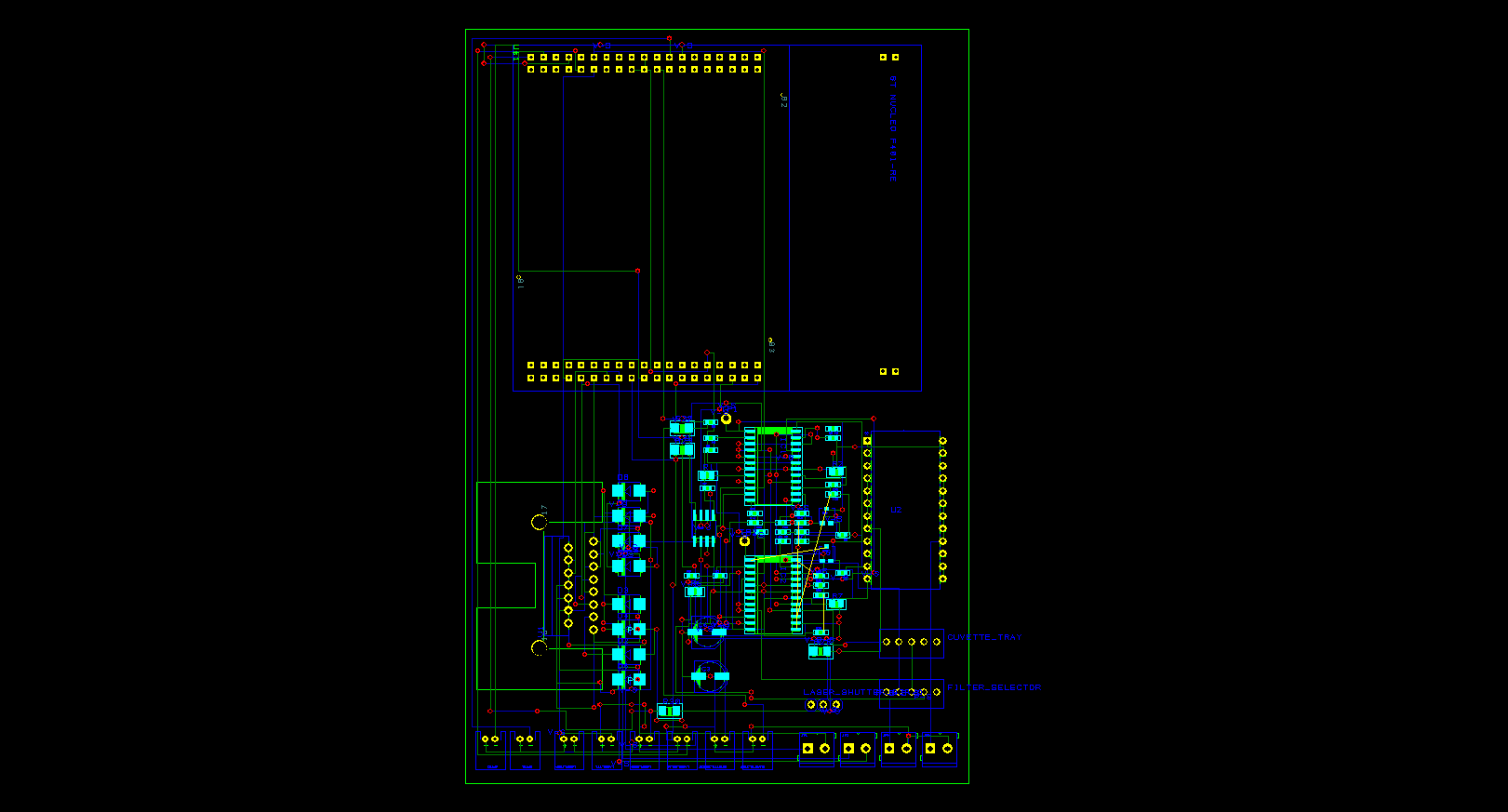
06/28/2014 at 22:26 • 0 commentsJust about done with the control board schematic and PCB design.. As I mentioned previously, I am going with a multiple option approach.... One option will allow you to just buy the breakout boards from ebay, etc. and solder them right onto the carrier board..which will make for a quick and easy solution.. The next would be to just buy the components and the nucleo board, drop them on and solder them up.. The first option would probably require two boards since the breakouts take plenty of space.. But it looks pretty good for fitting everything onto one board with the bare components..
Here's the option#2 with the bare components..after I fix a couple routing problems and such, I'll start with the carrier board for the first option..
![]()
![]()
This board allows the raspberryPi to offload the hard work to the nucleo...Opening and closing the cuvette tray/door..changing the 522nm and 550nm edge filters, monitoring and controlling the cuvette temperature, monitoring current draw from the peltiers, turning the laser on and off, controlling the laser shutter, and a few other functions.. It will talk to the raspberryPi through RS232 since the nucleo already has a nifty USB serial port..
-
Spectrometer Considerations
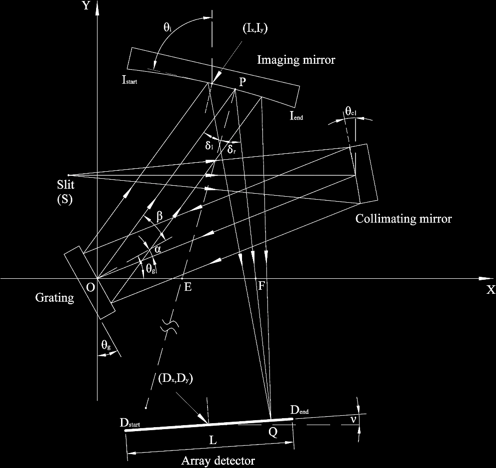
06/25/2014 at 22:46 • 0 commentsI am now getting to the point in the design where I need to hammer down exactly which configuration I am going to use for the spectrometer.. I've been sorting through tons of documents trying to determine the best configuration balance for cost, complexity, and resolution, etc..
I am fairly convinced at this stage that the Crossed Czerny-Turner configuration is the best fit for this application with all things considered..
![]()
Finding optics on eBay is slightly hit or miss... Locating the mirrors haven't been easy, and I think I may have to resort to purchasing new ones...Fortunately, they're relatively cheap. Here's what I am presently considering..
25mm Dia. x 50mm FL Protected Aluminum, Concave Mirror $37.50 each
I may revisit this since I have to work out the focal lengths, etc..This means that I will have to revise my diffraction grating, and some optics...but that was to be expected anyway.. This document was a great deal of help in making this decision Imaging Spectrometer Fundamentals for Researchers in the Biosciences––A Tutorial .. As was this http://www.ibsenphotonics.com/technology/spectrometer-design-guide and the comments in my bio, thanks to everyone who offered information.. it is appreciated!
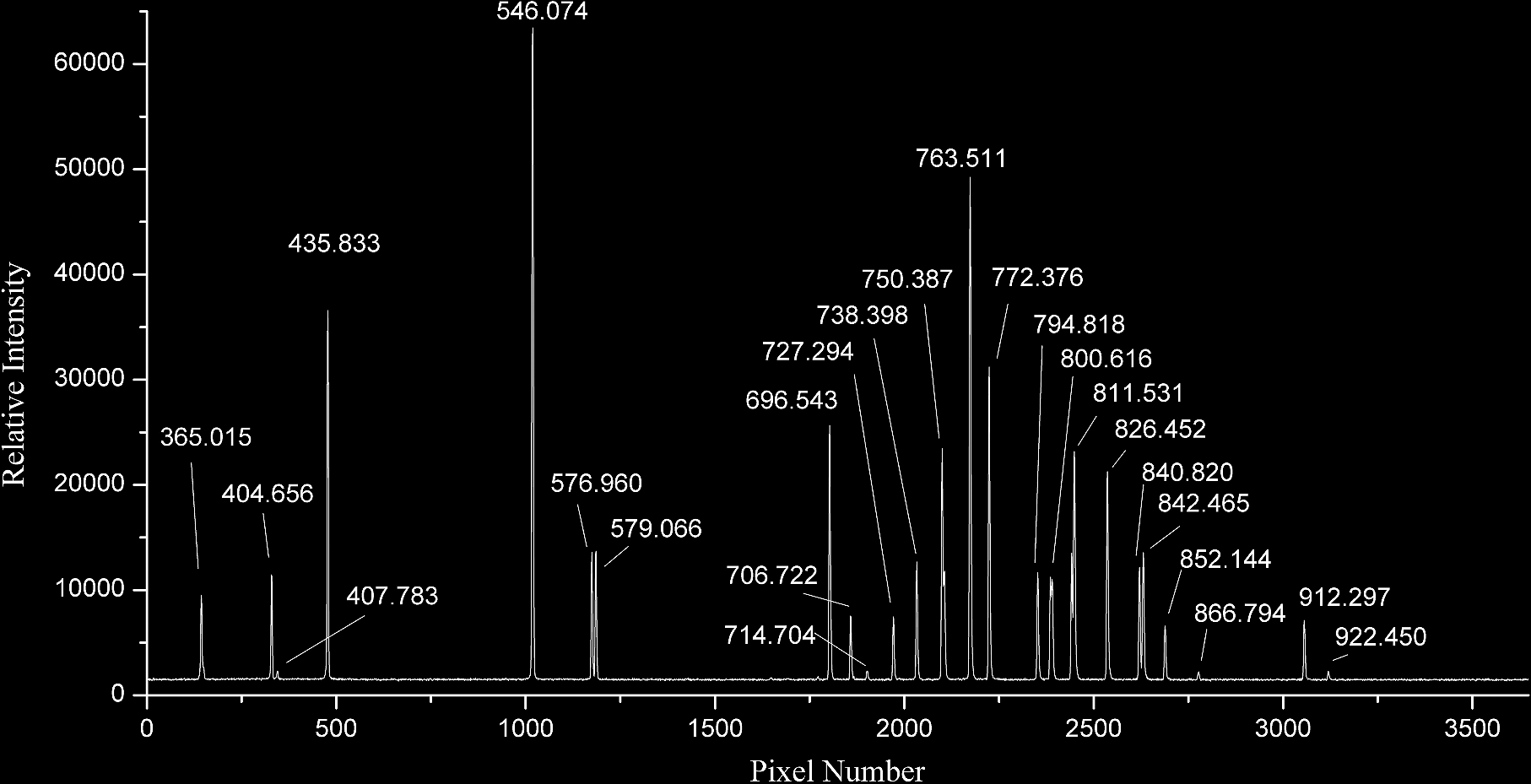
As for a detector... I have done some more research.... It seems the Sony ILX511 and the Toshiba TCD1304AP are both popular.. Ocean Optics uses them.. And you can get them both on eBay for $15.. I've been throwing the idea back and forth about designing my own driver, etc or integrating the dev board from the company and interfacing to that, or at least the middle ground of that and using their design on a custom board.. Time will tell there, when I get that far.. Ultimately, I'll be shooting for a configuration that results in an output like this mercury-argon calibration spectra...
![]()
-
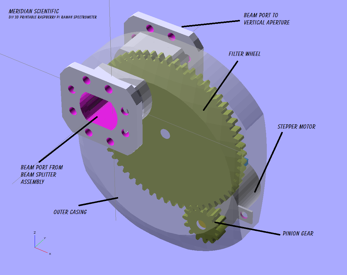
Filter Wheel
06/25/2014 at 04:22 • 0 commentsI'm starting work on the filter wheel assembly... I'm going with a semi-flat wheel with the filters mounted to its face.. It's a throwback to my first idea, and it turns out it's pretty common.. I only have two filters to mount in it for now, but it leaves room for expansion. The circumference is geared and driven by a stepper motor..I might add index points or maybe a rotary encoder to track position.. we'll see.. Here's a preview, I still need to split it in half, add screw holes, a center shaft and bearing, and the filter mounts of course...
![]()
Here it is in its place just off the beam splitter next to the laser emitter...
![]()
-
moreDetails
06/24/2014 at 20:28 • 0 commentsAdding more detail and filling in some gaps in the cuvette tray assembly and objective lens mount....
I am currently in the process of printing the test objective lens mount.. I'll post those pics as soon as it finishes!
![]()
![]()
-
Details
06/23/2014 at 23:26 • 0 commentsAdding a lot of details to get the cuvette tray and objective lens mount along with the drive bay adapter ready to test print... Including splitting the objects into the top and bottoms halves, adding screw holes, a lot of the mechanical aspects for the slider and so on.. Here's a small shot of what is going on...
![]()
I also have some progress on the circuit board prototypes... I'll be posting those soon as more parts came in today..!
-
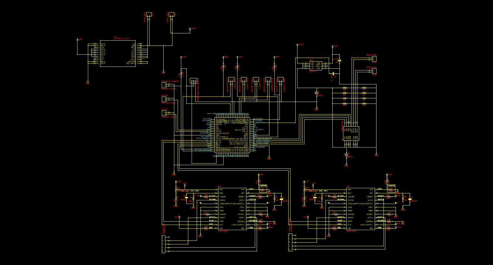
Schematics
06/19/2014 at 12:51 • 0 commentsOk, so.. I'm admittedly probably not the best with Eagle... And I ran into the limitation with the free version PCB size...so I am looking at switching to kicad....after I created the schematic in eagle of course...I tried converting it but the scale was waay off... So, anyway..until I get that sorted out..here's a sneak peak at the control board schematic.. I am handling the pcb's in probably a different way than most open source projects... I've run into several in the past where I'd like to build the device..but didn't want to go all in and either buy a board, or have one made, etc... so, what I'm doing for this is providing a few alternatives for the folks who want to build one but don't have all the options.. So, 1st option is buy the pre-made breakout boards that I will list from places like adafruit and sparkfun...and slap those on a breadboard and wire it up yourself using the schematics I'm providing...will work just fine.. 2nd option is to take the eagle(or kicad, etc.) files and either mill it, etch it, or have it made...then populate it with the breakout boards from the same as the previous option... or 3rd you can download the alternative board layout which has all the parts integrated on the board in one place.. This would be the more standard option and provides a nice clean setup...
At any rate, here's the first half of the controlBoard... It has the nucleo and two easydriver stepper drivers, a lm2825 switching power supply and a couple connectors.. The second half will have the HBridges, etc...
![]()
-
CuvetteTray, Display/Keypad, and ObjectiveLens Assembly...wip..
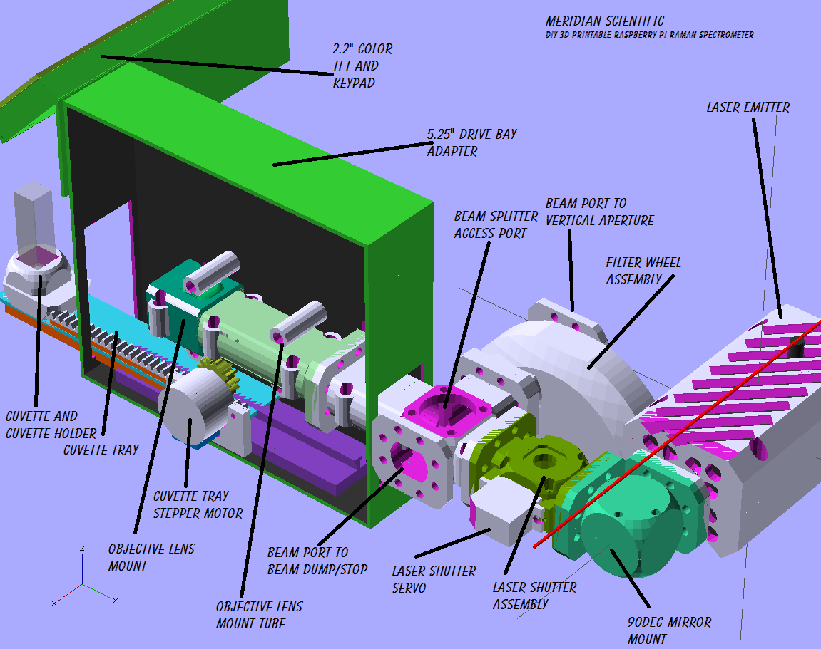
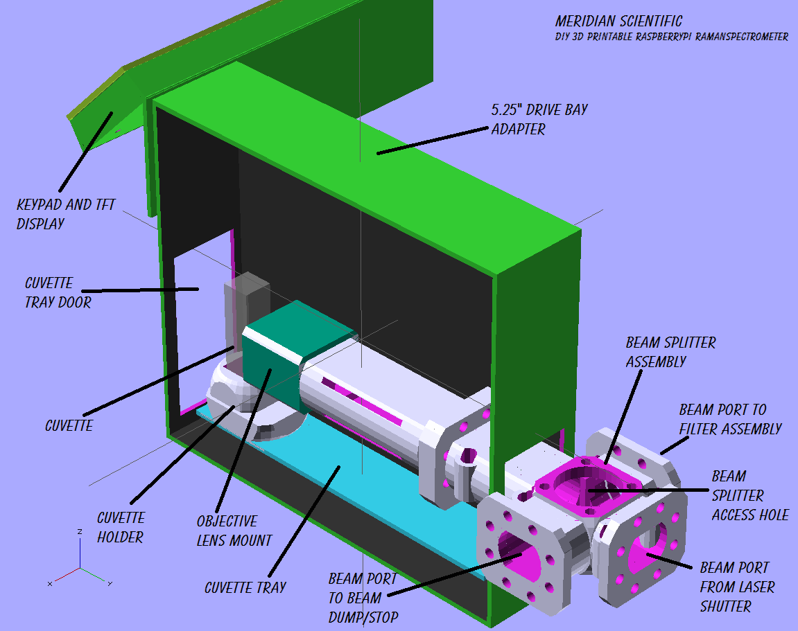
06/17/2014 at 15:16 • 0 commentsSo, just a quick update... I've started work on the cuvette tray assembly which is kinda the center of business right now....it holds the objective lens and mount...the beam splitter mount attaches inside...the display and keypad attach to it as well..
To arrange everything into the confined space...I've had to do a little reorganizing... The Laser is now attached to the mirror directly, then the laser shutter is after that at a 90deg angle...then the beam splitter comes off of that into the drive bay where it attaches to the objective lens and faces the cuvette...I'll post updated renderings showing that asap...
Meanwhile here's a couple renderings of what I've got going on it so far...lots to do...I have to work out the stepper motor rack and pinion for the tray, the tray slides... the cuvette holder itself (I don't like the one in the pics)... Also need to work out the attach points for the beam splitter and objective mounts... the display face needs some finishing, and so on...
Side view...with cuvette tray retracted...
![]()
![]()
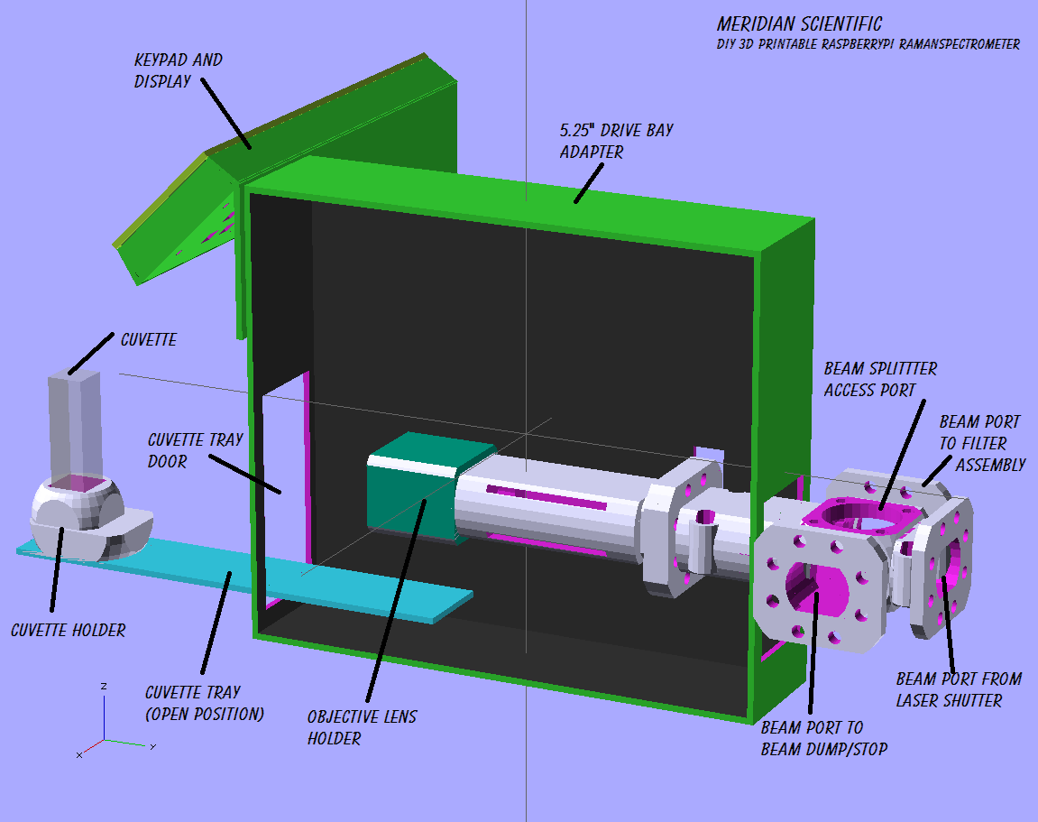
A view with the cuvette tray open...
![]()
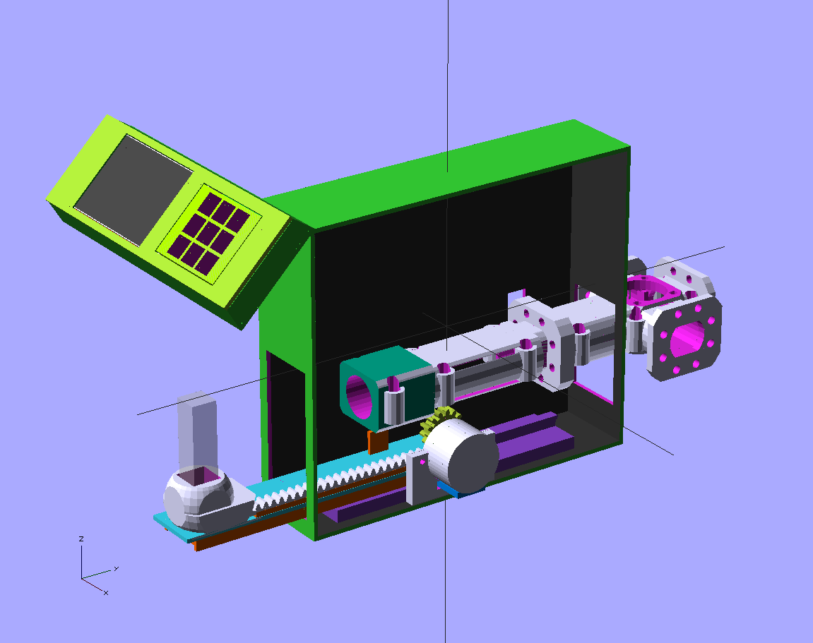
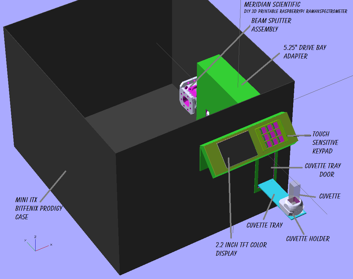
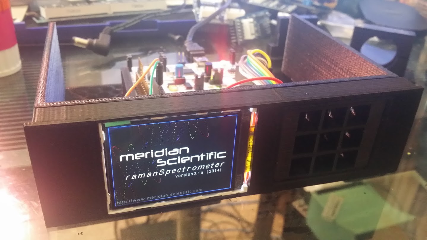
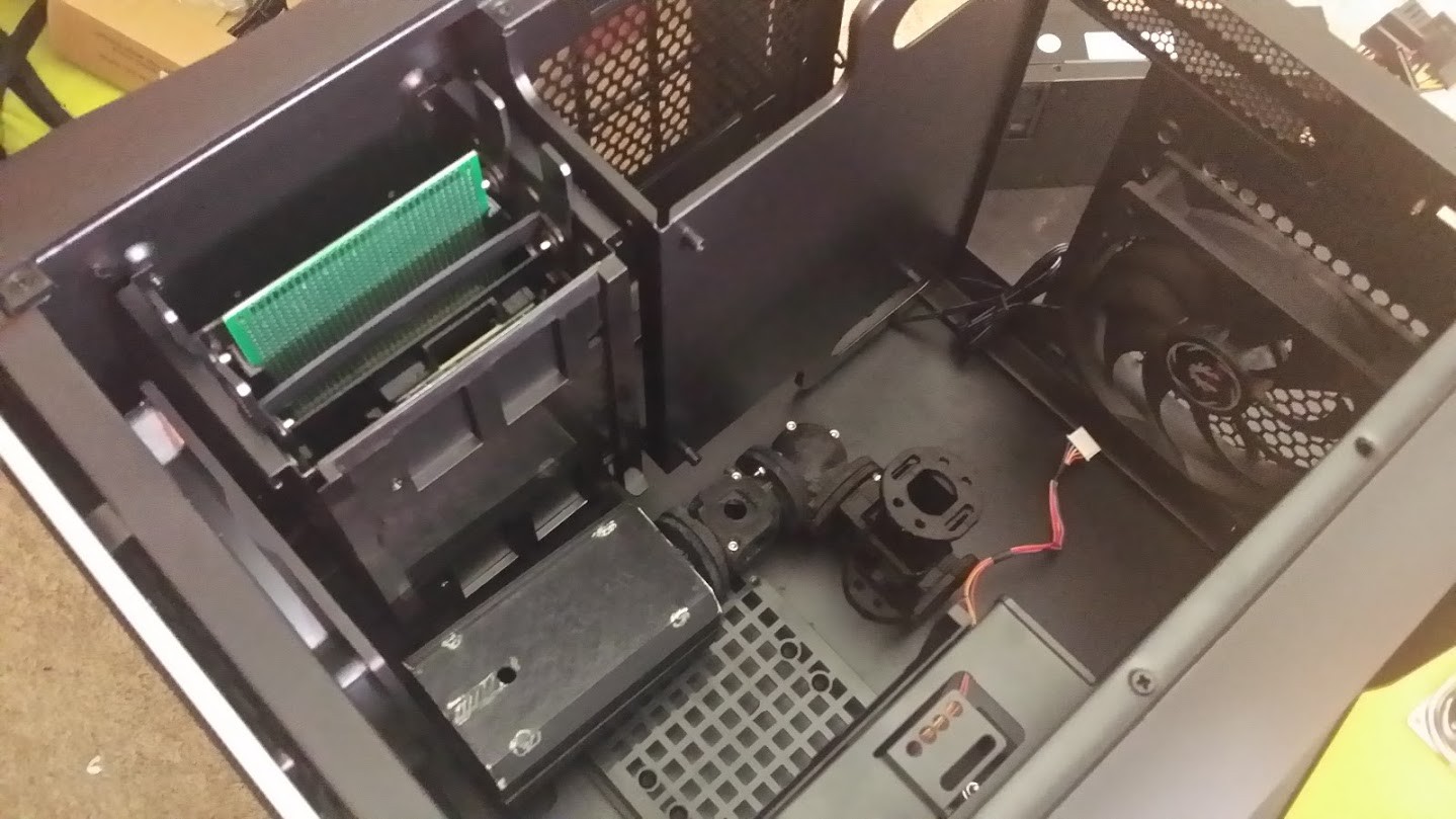
And a sneak preview of how it is sort of going to look in the ITX case....doesn't do it justice really...but it gets the point across for now...
![]()
That's all for the moment..but I am getting ready to get some schematics and stuff up for the controller board and display board... More to come soon! -
Successful Test
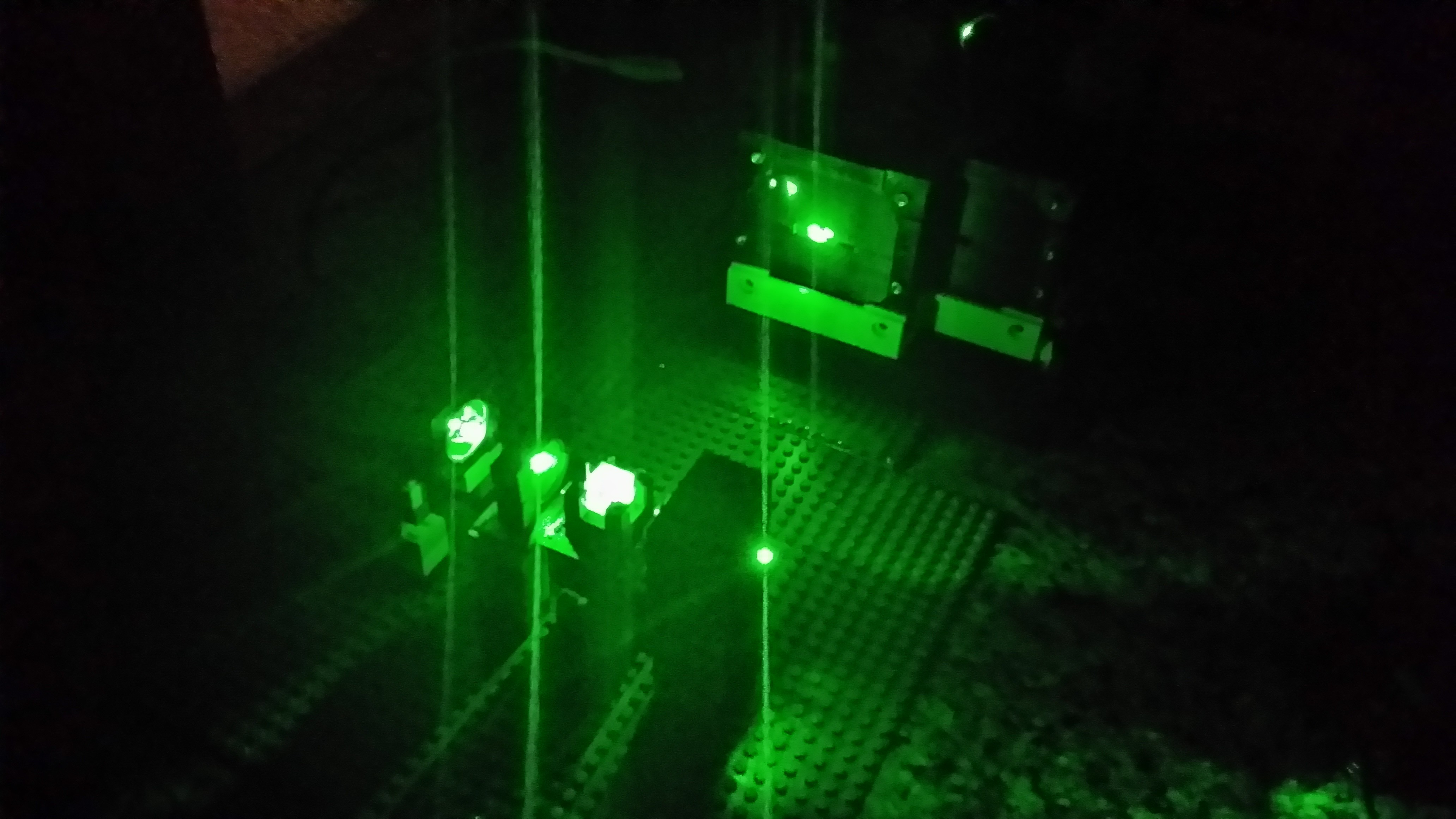
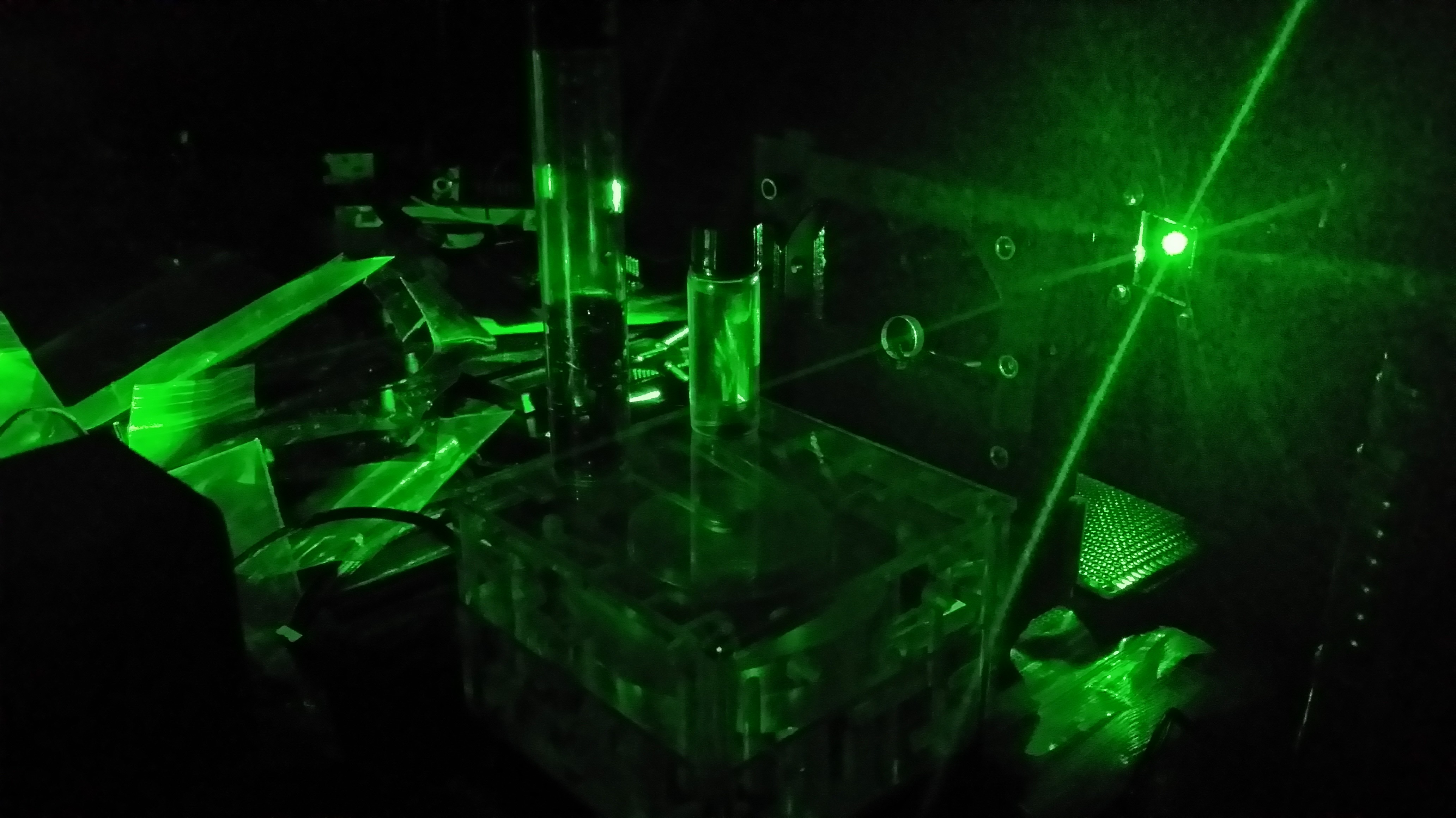
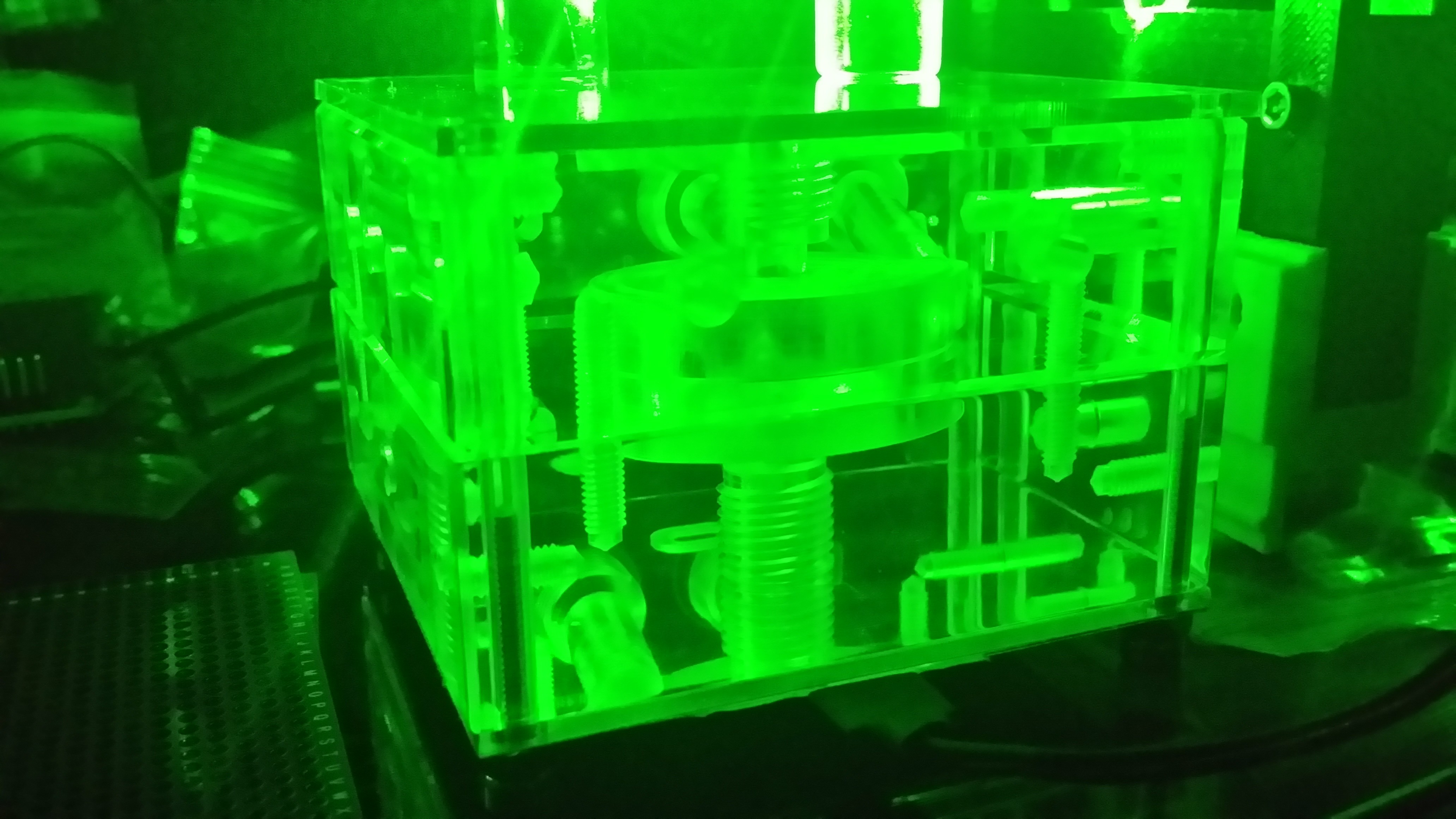
06/14/2014 at 14:24 • 2 commentsSo, I have been testing and experimenting with the filters, etc.. trying to get a spectra from a sample of tap water using a makeshift setup... It works, I was able to get a faint sign of progress.. Enough for me to go on anyway.. Here's some shots of my tests..
Here's the first run...Yes...those are legos providing the height for some of the optics.. :) (Images of the spectra are down further... )
![]()
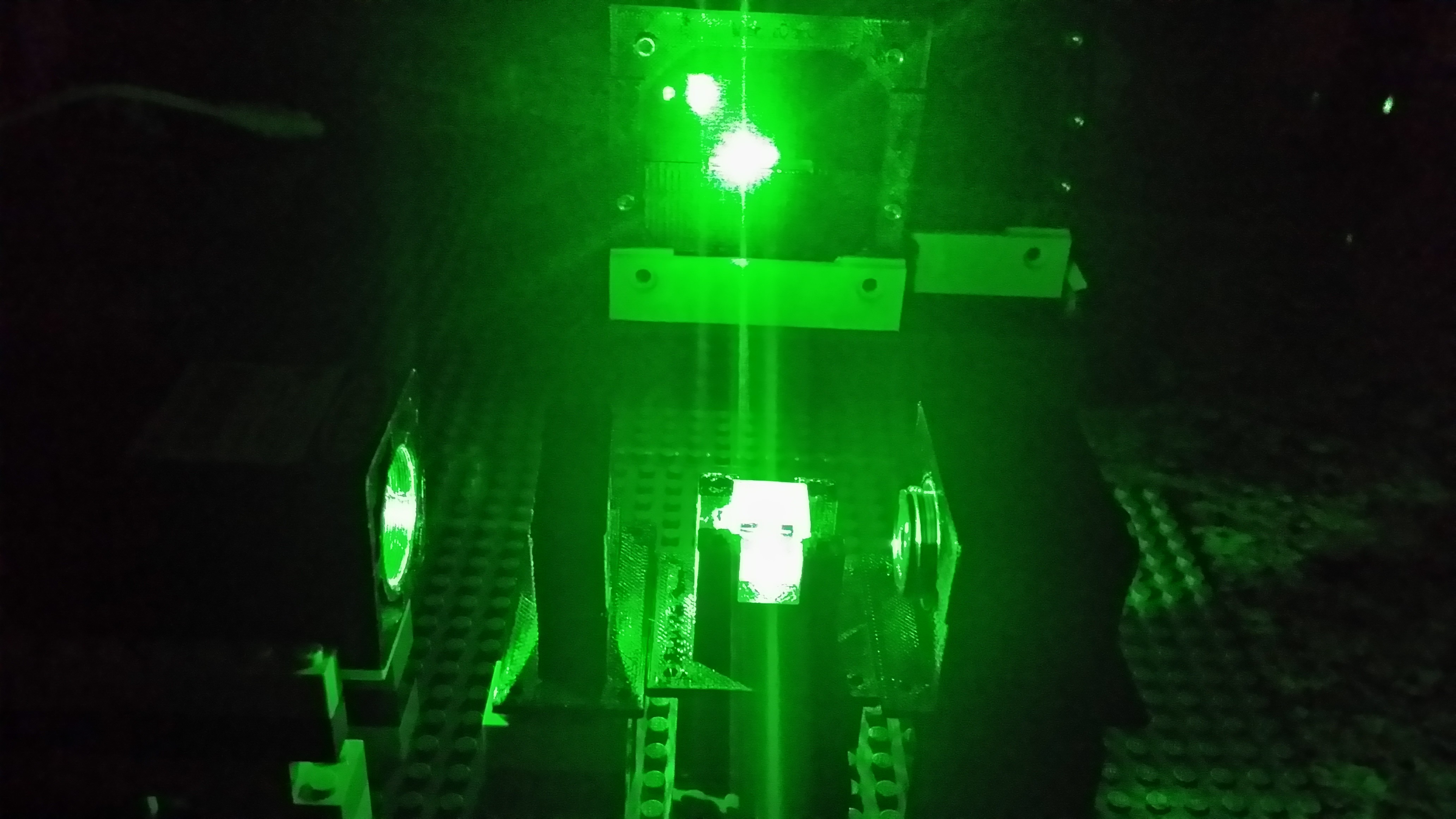
Another angle..
![]()
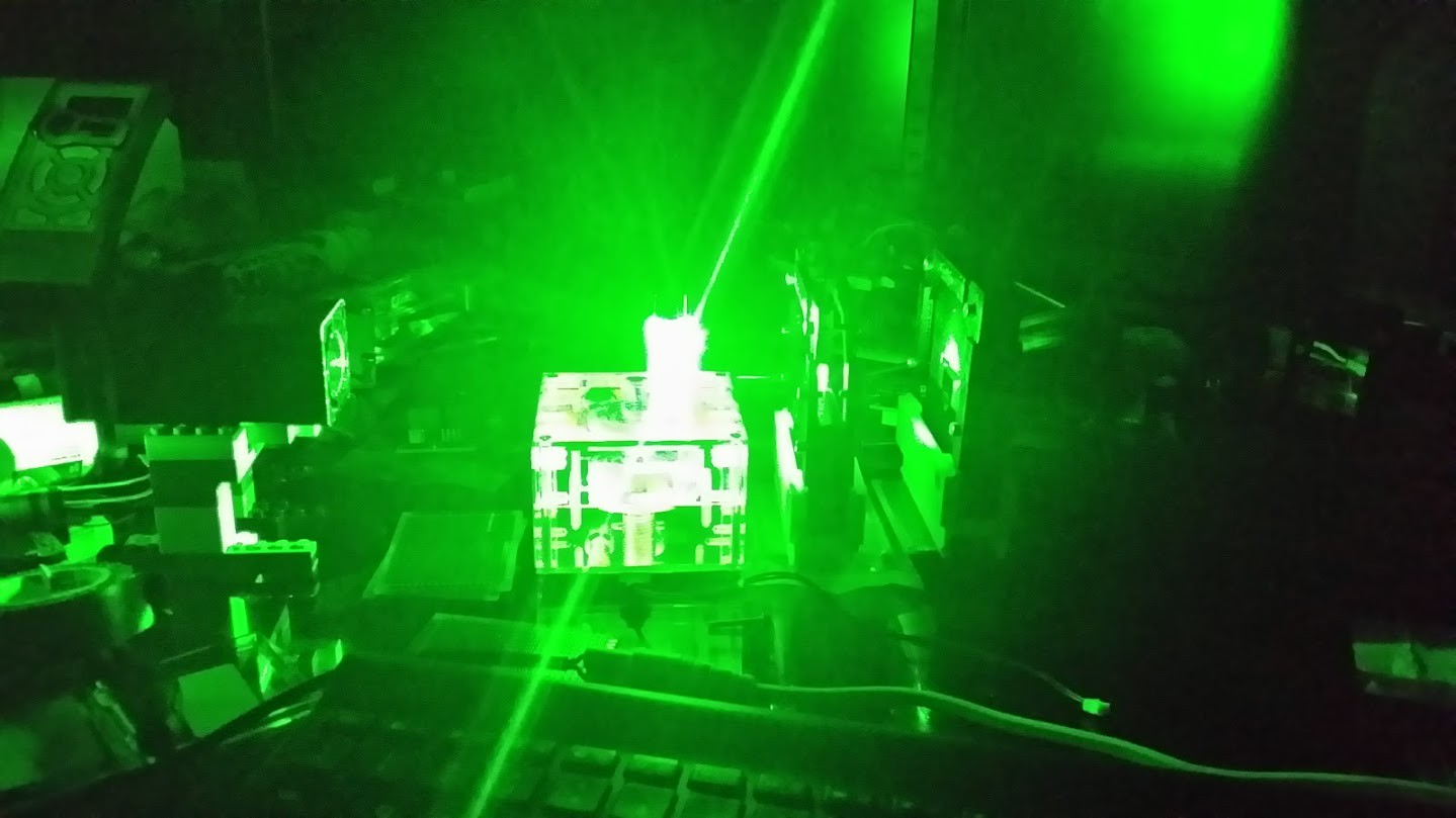
Here's a shot of the second round... That's the sample in the middle that's so bright..
![]()
![]()
![]()
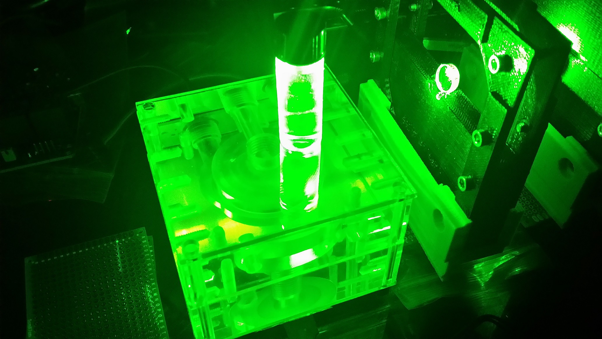
Everything looks so cool under laser light...
![]()
Not much, I know... but this was taken with my cellphone camera by hand...the color didn't come out well and the full lines aren't showing in these for some reason..but you could clearly see the red when the sample was in front...
![]()
![]()
I've been researching more imaging devices...and I'm probably going with a linear ccd or a MEMS micro spectrometer like the hamamatsu C12666MA....
And some other things that have been going on...
Motors for the lens assembly...
![]()
![]()
![]()
The display and interface micro...
![]()
![]()
A test print of the newer design...
![]()
-
Quick update
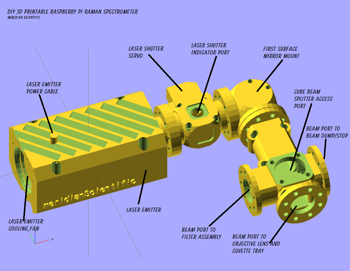
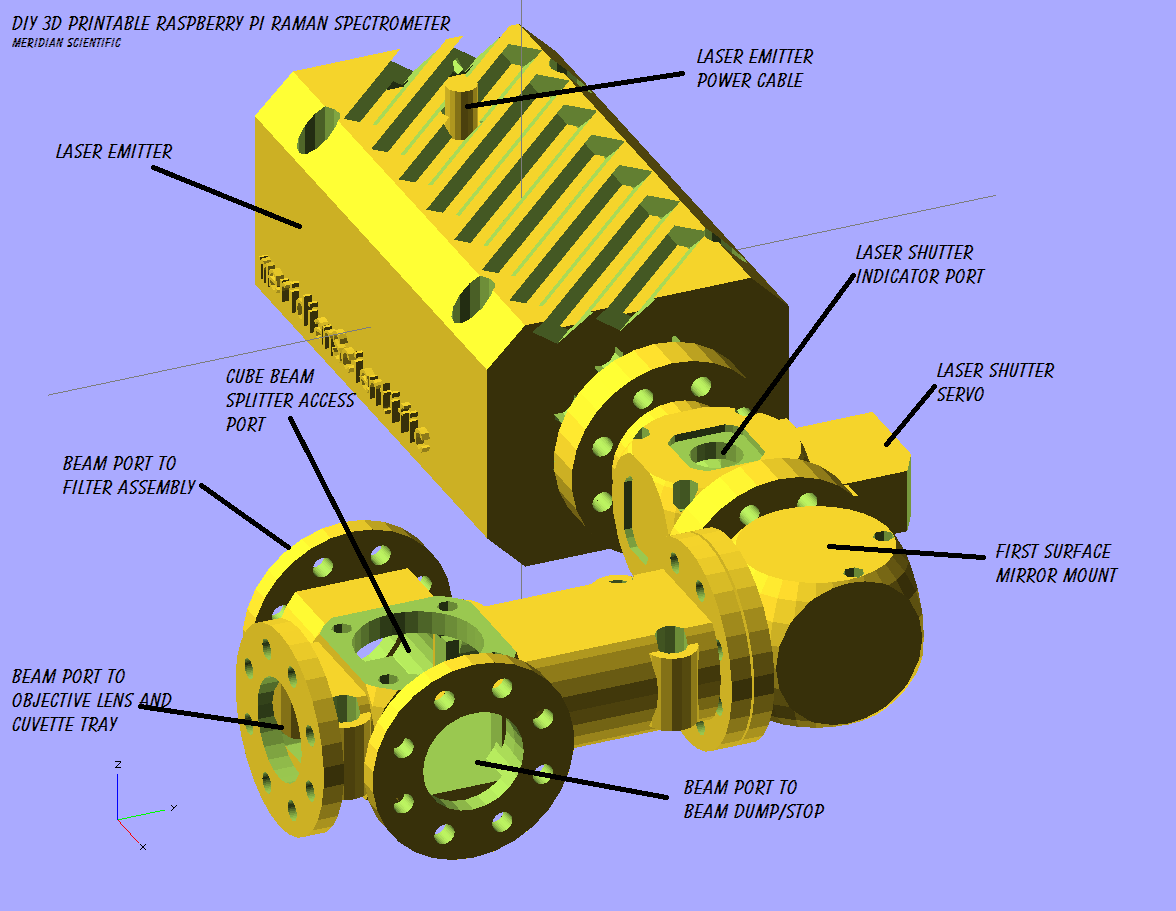
06/11/2014 at 08:11 • 0 commentsSo the redesign is coming along nicely in my opinion.. Here's some shots of the assembly as it stands so far.. I'm in the process of printing these out as I type this so I will have some photographs of those soon... It was also suggested to me that I label things in the pictures...so here goes!
Here's the optics system up to the point of the beam splitter... I am starting work on the objective lens and cuvette tray assembly tonight..
A sort of top down view....
![]()
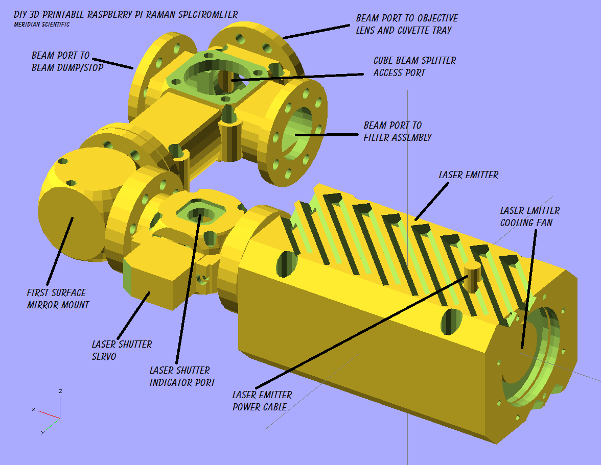
A view from the right...
![]()
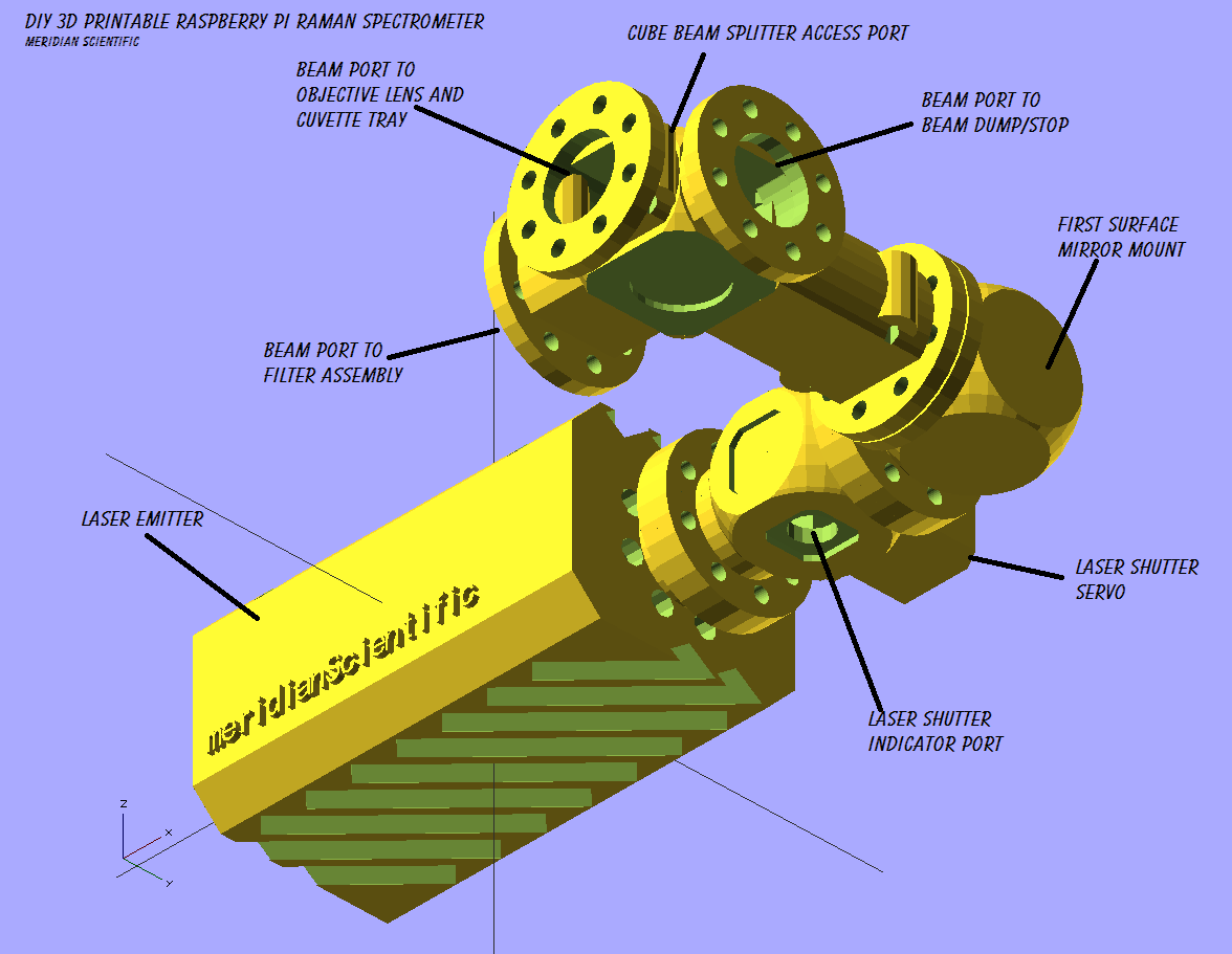
A sort of view from the top down..
![]()
From underneath..
![]()
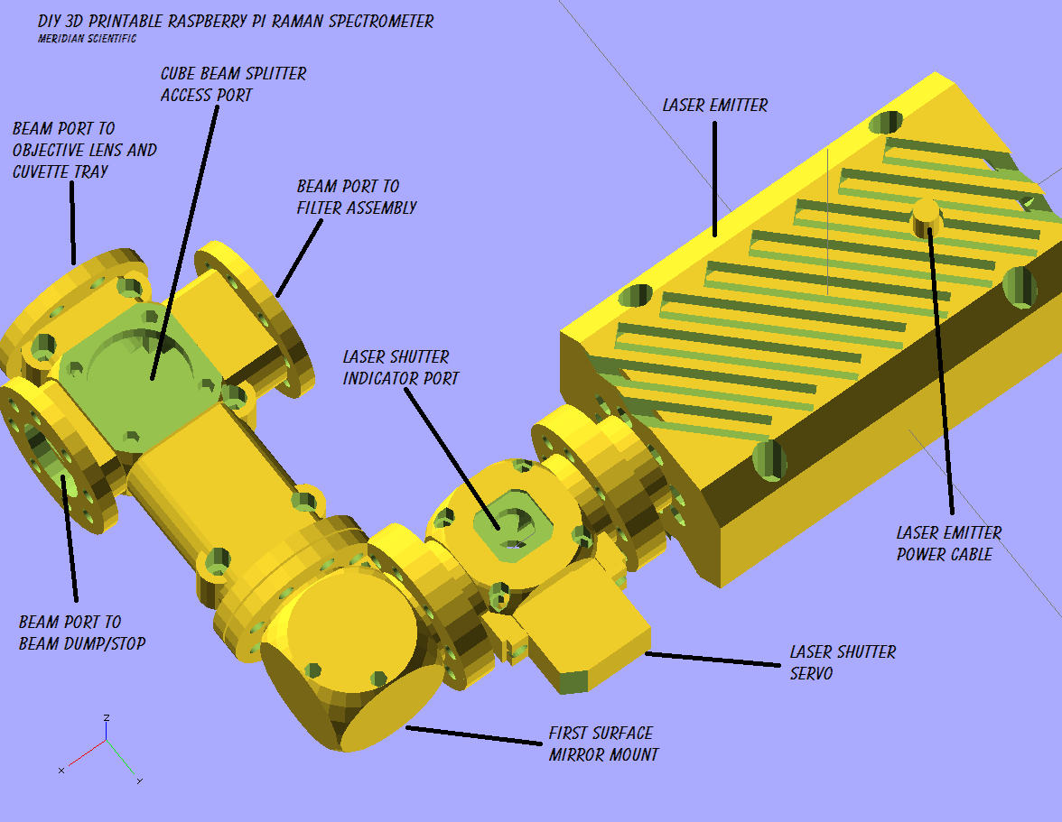
And from the top and above...
![]()
These modules are based on the optics I have purchased from eBay... It is my intention to make them parametric, and also provide direct links to specific optics you can purchase from places like Edmund and I will provide the parameters for each one.. This way it will allow for a very customizable option as well as a standard to base everything from...
Here is a sample list (NOT FINALIZED) for optics that I will be providing the parameters for... This is all from Edmund Optics.. http://www.edmundoptics.com/ Mind you......this list is all brand new components.....not from eBay, so the prices are higher... It may/will change and I may include other manufacturers, I want to find the best choices for the best prices....!!
- $15.00 Stock No. #69-245 4-6 Wave Mirror 25.4mm Diameter
- $85.00 Stock No. #69-867 550nm Dichroic Longpass Filter, 12.5mm Diameter
- $90.00 Stock No. #64-594 525nm OD 2 Shortpass Filter 12.5mm Diameter
- $140.00 Stock No. #45-111 12.5mm 50R/50T Standard Cube Beamsplitter
- $29.50 Stock No. #32-489 Double-Convex Lens, 25mm Dia. x 25mm FL Uncoated
- $175.00 Stock No. #68-843 532nm Hard Coated Laser Clean-Up Filter, 12.5mm Diameter
- $105.00 Stock No. #43-218 1800 Grooves/mm, VIS Holographic Grating, 12.5mm x 25mm
More updates soon!!!
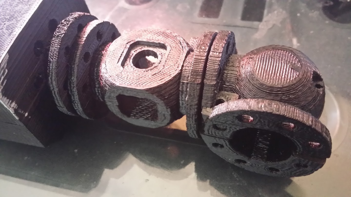
Update! Here's some real photos of the above!
The beamSplitter mount just finished off the 3D printer....still has the supports under it..
![]()
A partially assembled test of the laser emitter case, the shutter, surface mirror and beam splitter...
![]()
I'll try to get better pics up soon!
ramanPi - Raman Spectrometer
The open source 3D Printable Raman Spectrometer using a RaspberryPi and easy to find off the shelf components..