What is this?
The goal is to make easy to plug together sensors to make something new and interesting quickly. Typically one uses a breadboard, but this is not very field-able and wires easily pull out. Also having something small is much nicer to use than something bulky. Also making PCB's is getting easier these days. So when you make a new sensor why not add a simple edge mount PCB pattern that enables your to connect to an ecosystem of other sensors.
Common Hardware Interconnect
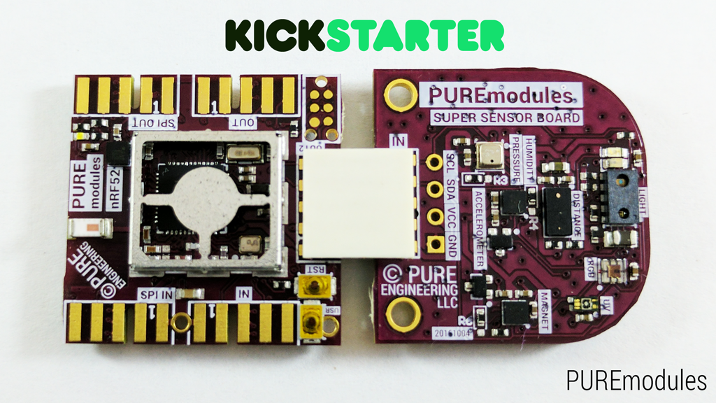
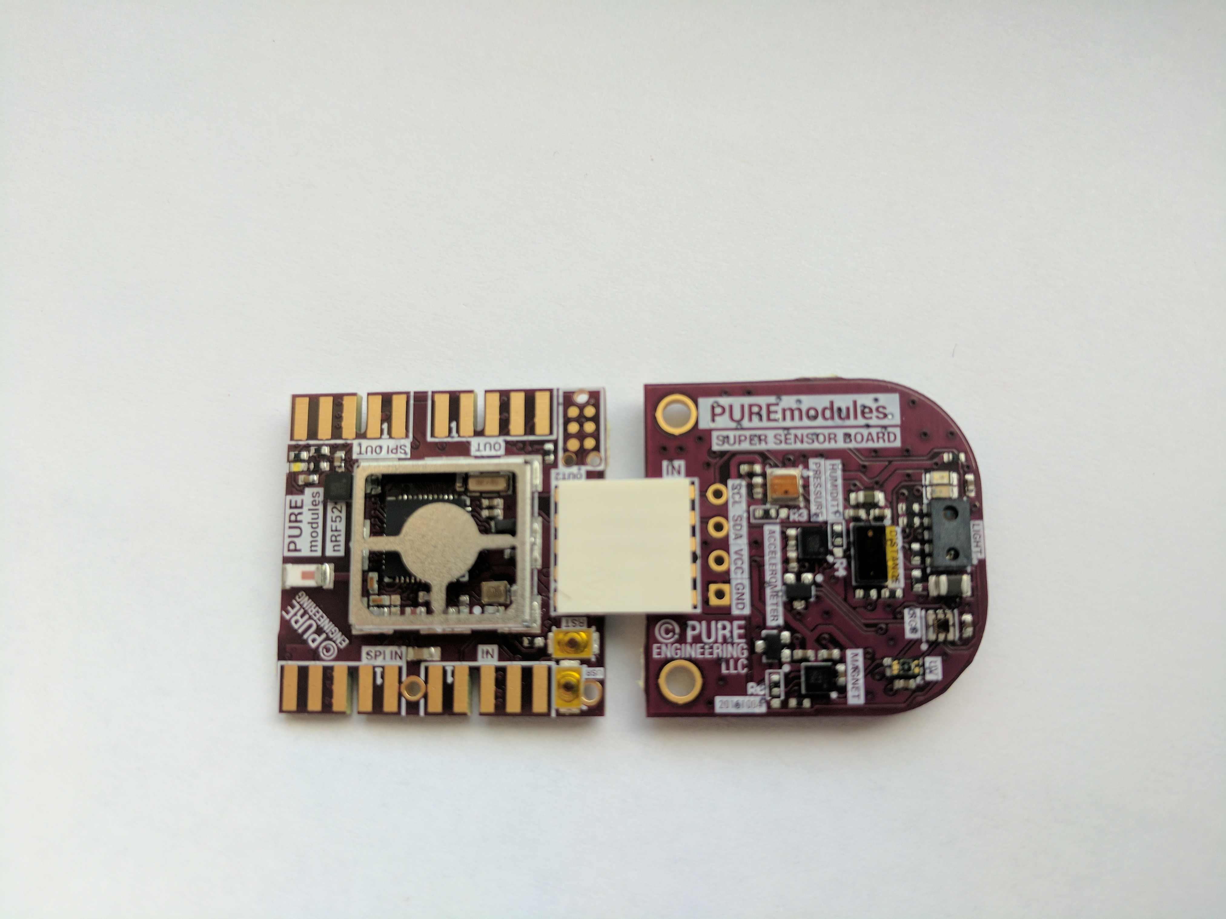
To allow for prototypes to be small and low cost we have chosen a 62mil PCB edge connector as the hardware interface. This interface has 0 components to be added to a PCB to allow it to connect to the system by a low cost connector. By using a PCB edge the costs remain low for the sensor and can be added to nearly any development board with no additional cost.
The 009159010061916 AVX Open Ended Card Edge: BTB was chosen as the default interface to connect two PCB's together. The connection is very robust and allows for many insertions and can carry higher currents if needed. The density is high and doesn't use very much PCB real estate.
We have chosen I2C to be the primary interface to adding new sensors to the system. I2C was chosen for its simple two wire interface and multi drop architecture. The protocol is typically used for low power hardware sensors, so for most common sensors there is no interconnect logic.
The common pin-out is as follows
- VCC system, 2-3.3V range. typically could be directly tied to a lithium coin cell or two AA's in series
- RAW battery, 3.3V-15V range. cound be a li-ion battery, wall wart, solar cells, etc. this raw battery is typically regulated down to 3V-3.3V
- GND, Common ground reference point
- SDA.
- SCK
- GPIO (typically would be the uart TX from the micro-controller)
- GPIO (typically would be the uart RX to the micro-controller)
- GPIO
- GPIO
- GPIO (typically this connects to an interrupt open collector bus to the micro-controller
Common Firmware platform
We have chosen contiki as the the foundation for the system. Contiki has been used for many years now and is very stable and well supported. It was designed around low power, low resource, wireless systems. This is an ideal fit for a Modular Sensor Architecture.
Common Sensor Communication
MQTT was chosen as the data transport layer due to its extremely lightweight overhead. It easily allows scaling from one sensor to millions. It is well used and supported. Both MQTT and MQTT-sn are utilized depending on the RF communication interface. MQTT-sn is typically used over MQTT due to its lower overhead.
Common Data protocol
To describe data moving from A->B Protocol Buffers and more specifically nanoPb is used. By using a compact and common protocol data can be digested by almost anything simply by publishing your .proto file.
Common Micro Controllers
We have chosen two micro controllers to be the primary supported micro-controllers under this sensor architecture.
nrf52 : Nordic's latest SoC had handle almost anything thrown at it and still remain a low power.
cc2650: TI novel three core architecture allows for extremely low power systems.
Analog Sensors
For adding Analog sensors to the system, the preferred route is using an I2C ADC converter chip. we highly recommend the ADS7924 due to its low power standby current and the ability to control the power of the analog sensors to reduce power usage. The Mics 6814 sensor module uses this chip.
Extra GPIO
We highly recommend the Semtech SX1508B GPIO chip. This chip is very versatile and low power. it most likely can do what you need. We recommend using this I2C GPIO over the micro-controller pins mainly to keep your pin count low and flexible. Also this IC provides level shifting if needed and when going to low power sleep states, you won't have to mess with the GPIO states of the micro-controller. Lastly by using I2C instead of pin on the controller we can expand to a complex system very easily.
UART expansion...
Read more » Pure Engineering

 Danie Conradie
 Atheros
 Maker-fabs-J