-
i have an idea!
09/04/2016 at 16:38 • 1 commentIt has passed some time since i upload a log for this project, a lot has happened in my personal life and in this project too.
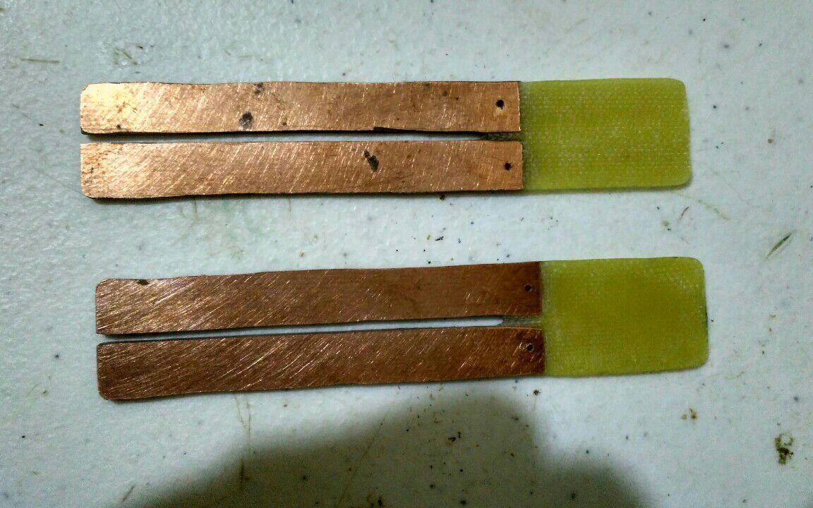
First, i finished the prototype of the sensor and i made two of them to compare their performance. I used some servo cables with the white wire cutted, and soldered them . I isolated them with hot glue and i finished the surface of the glue with my hand torch. I still think that an hydrophobic coating is the best option but is to expensive for me to buy it right know. This is the result:
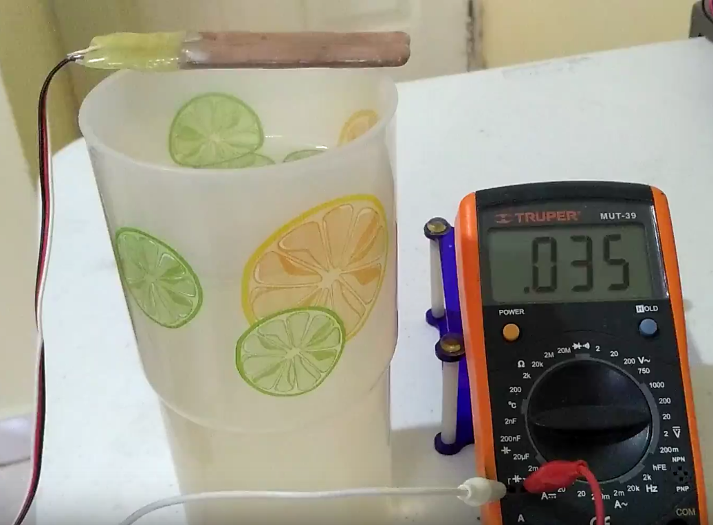
So i tried to test it with my multimeter to see how big the capacitance was, and i got:
That means 35pF, that's really low. Then i tried to see the change on the value of the capacitance when it was out the water vs when it was in the water... no luck!So then i thought, why not both? I put both of my capacitive sensors together with an elastic band with the plates facing each other with opposite polarities. This allowed more water between the cooper plates, the result is in the next boring video :P
So i got around 14pF of range, which is an small variation. Then i tried to measure the capacitance with an arduino using the simplest "charge and discharge measurement of time" method using this code:
https://www.arduino.cc/en/Tutorial/CapacitanceMeter
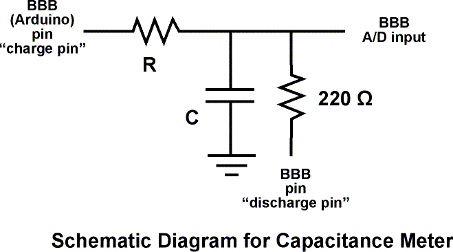
and this circuit with R = 50Mohms :
and i got this super noisy readings:
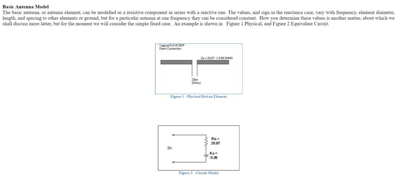
I tried some digital filtering but still, the noise were far bigger than the range i needed to measure. So after some internet surfing and chatting with a friend i realized something.... this circuit is a freaking antenna:
So, i turned off all my RF sources around me, by bluetooth speakers, my laptop wifi, i set my phone on plane mode and this happened:
The values became really stable (after the red line). And i notice that some other people that built capacitive soil moisture sensors had problems like this, for example, miceuz from wemakethings.net maker of the "CHIRP" the soil moisture sensor sold on adafruit.
http://wemakethings.net/2013/06/07/chirp-plant-watering-alarm/
On his words:
So i realize that if i would want many sensors working together communicating wirelessly and not crashing with other RF signals, i would have to try a different approach. Miceuz wrote this about the issue:
So after surfing and reading a lot, i found the blog "Zero characters left" where "drxzcl" talks about the attempt to make a similar sensor. In fact, after reading the 76 comments, i found out that it was that post that inspired miceuz to build his own, at least i think so.
http://zerocharactersleft.blogspot.mx/2011/11/pcb-as-capacitive-soil-moisture-sensor.html
In those comments also there's a lot of people affirming that commercial capacitive soil moisture sensors works above 80Mhz... why? because on those frequencies the effect of soil minerals is way less than in low frequencies. So this means that a sensor working on high frequencies have better chances to sense just the amount of water on its surroundings and no other elements or materials.
And maybe this was luck, but on hackaday main page i saw this:
http://hackaday.com/2016/03/01/color-tv-broadcasts-are-esp8266s-newest-trick/
It seems that the ESP8266 is capable of producing those frequencies using his Integrated Interchip Sound serial port.
Wouldn't it be great if the low cost most famous wifi module/microcontroller could be used to make this project a reality?
Does anybody know how to use that thing? :)
-
A quick prototipe
07/29/2016 at 05:47 • 0 commentsWhile reading about how to measure capacitance i found what it seems to be the simplest method when using a micro controller: https://www.arduino.cc/en/Tutorial/CapacitanceMeter
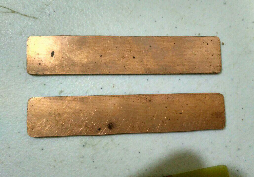
So i improvised a little to build some capacitive probes based on a FR4 double sided cooper board. Everything was made using a rotary tool, so it isn't perfect, that's why i made two, to compare the performance between both.
The next step is soldering some cables, connect to an arduino, and isolate the board completely. In the previous log i talked about the challenge of finding the right kind of isolating coating or cover. Right know i think that the Neverwet alternative mentioned on the comments of the previous log is a good idea, but i'll have to save some money to buy this coating kit.
https://www.amazon.com/Oleum-274232-Never-Multi-Purpose/dp/B00DNQBFAW
Once i have my probe ready, i'll test it on a glass of water and see what happens.
-
Shaping the sensor, shaping the world
07/26/2016 at 04:47 • 4 commentsAll of the capacitive methods listed on my previous log have something in common, they need a capacitive probe where the soil acts as the dielectric core.
I found that coplanar electrodes is the best way to emulate a capacitor using cooper pads on a printed circuit. In the case of a double sided pcb, we need to use the same polarities on both sides of the pcb, in order to ignore the material that the pcb is made of (FR4, paper fiber, etc).More info here: http://zerocharactersleft.blogspot.mx/2011/11/pcb-as-capacitive-soil-moisture-sensor.html
Is important that the geometry of the board allows it to be placed easily on the ground. Also, all the probe body needs to be water isolated because the material the pcb is made of can store moisture on the long run (FR4).
Doing this can result in other problems, the same material isolating water from the board, can begin to store water, causing drifting problems measuring capacitance.More info about this, here: http://www.deepdarc.com/2011/09/08/square-one/
-
Searching the best and cheapest way to sense moisture
07/23/2016 at 07:26 • 0 commentsThe core of the project is to achieve the ability to sense the moisture of the soil on a crop field. The reason for choosing the capacitive way over the resistance method is to avoid the rust on the electrodes, dielectric terminals doesn't need electrical conductivity, therefore, they can be isolated and protected from water, air and dust.
The capacitance or the dielectric permittivity of the ground changes with the level of water content in it. There's 5 main ways to sense those changes:
1. Using a 555-like timer, and use the changes of capacitance on the ground to change the frequency of the output signal.
2. Using a dual opamp in an astable oscillator mode and measuring the frecuency of the output signal.
3. Using an opamp in integrator mode, where the cut off frecuency is based on the capacitance of the ground.
4. Using a microcontroller to generate a signal above 1Mhz and using a low pass filter to alter the output voltage, based on the capacitance of the ground.
5. Using a capacitance meter IC.
I haven't decided which method i'm gonna test first.
Info about the methods:
http://electronicdesign.com/analog/use-analog-techniques-measure-capacitance-capacitive-sensors
http://wemakethings.net/2012/09/26/capacitance_measurement/
A cheap capacitive soil moisture sensor
In order to achieve the first stage of precision farming, i want to create a cheap soil moisture sensor with wireless communication.
 Valentin Ortega