 willbaden
-
Controller Box
08/05/2016 at 01:42 • 0 commentsThe controller box started out as a headless control with the USB to the UNO being fed out of the bottom.
![]()
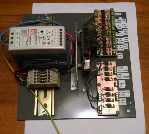
It did not have an estop, start, hold or reset button. The guts were a lot simple too. The back plane just had a 24V power supply, UNO, and a input/output opto coupled boards.
![]()
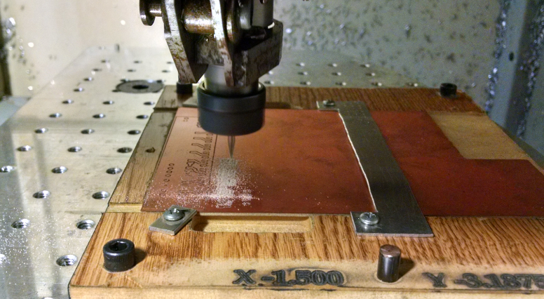
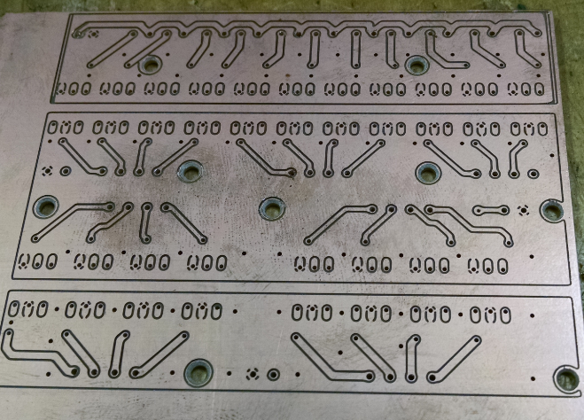
The UNO is running GRBL with few modifications to the settings. The input/output boards were designed with Eagle. Then milled out on the CNC:
![]()
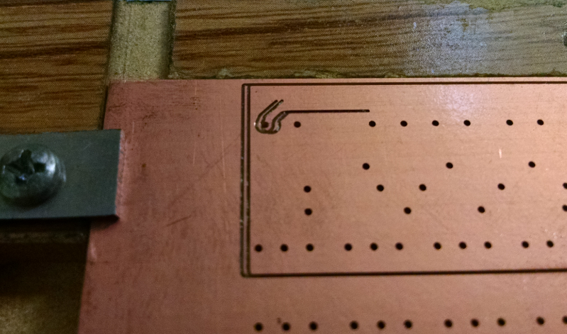
Flipping between the sides, I ran into an offset issue though and had to adjust.
![]()
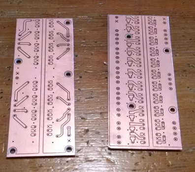
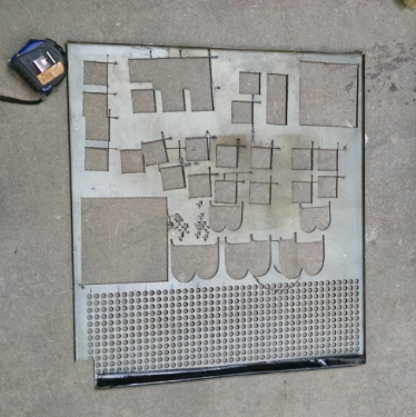
Both boards were milled on a single double sided pcb:
![]()
These were cut apart and ready for components to be populated.
![]()
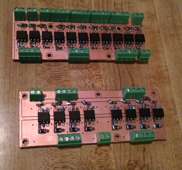
Soldering the surface mount resistors was a task. Seeing reflow ovens soldering, makes me want to build one myself.
![]()
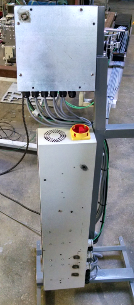
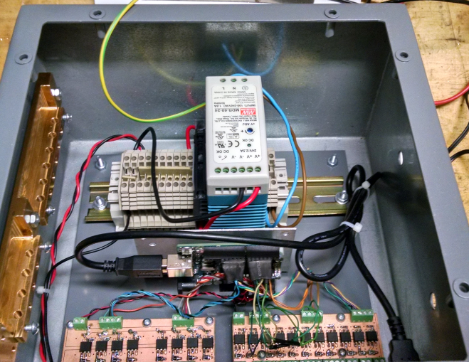
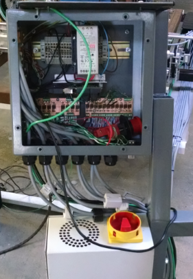
The backplane fit nicely in the enclosure:
![]()
To the left is a ground bar that distributes the ground connections and also an attempt to ground out the shielded cables. Below is a complete view of the ground.
![]()
The stepper driver cables were then wired on the bottom of the pcbs.
![]()
There was a temporary estop attached while some testing was done to verify cable routing. Along the way, there was issues with poor solder joints and miswiring between the UNO and output board. When that was sorted out, testing could begin. The lower right of the controller box had a bulkhead USB passthrough that allowed a laptop be connected and power up the UNO. The laptop ran Universal GCode Sender and was painless in operation. A little effort was required in installing, but came down to reading docs to figure it out. The first few cuts by the plasma table were nerve racking, but worked fine for the most part.
![]()
![]()
And more testing was done:
![]()
Cambam was used to make the letter B, but the majority of testing was hand written code that cut out a square. The circles along the bottom was not cut by the plasma table. They were already present.
Then the realization that noise in an HF start is a challenge.
The first symptom that appeared was GRBL restarting. Randomly when the plasma torch would fire, GRBL would restart. This stopped the program being fed via File Mode of Universal GCode Sender. From what I remember (I know it has only been a few months) at that time, the table and controller/driver boxes were not connected electrically. Tieing them together helped with the GRBL restart.
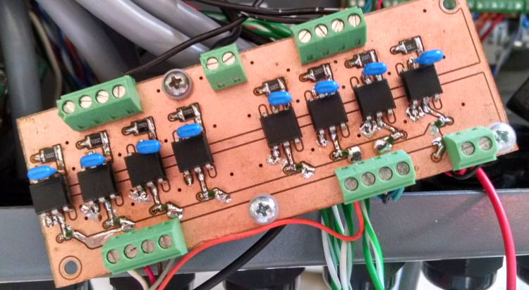
Then when the hard limits were wired in, they started to trip randomly during torch fire. Thinking it was some noise feeding in from the input and output cards, capacitors were added liberally across 24V inputs (.1 uF)
![]()
5V signal to UNO (.33 uF):
![]()
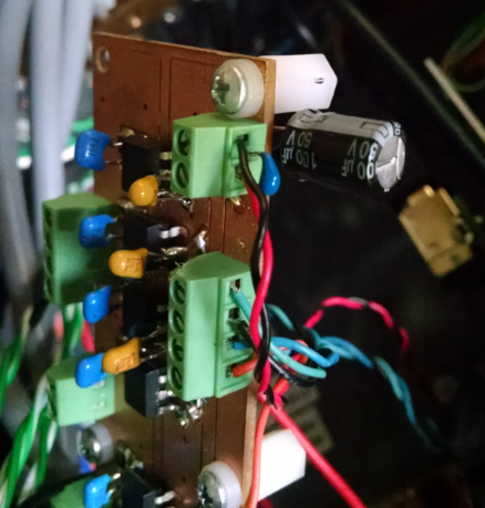
I don't have pictures for the next individual steps of capacitors, but this photo shows multiple capacitors added: 1 uF to the 5V side in parallel, the 5V power input, 100uF and .1 uF caps were installed.
![]() Still had the issue with the hard limit. Along with the hard limit issue creeping in, the relay that turned the plasma torch on and off was not firing all the time or was firing and then immediately shutting off. So a 100 uF cap was added to the 24V power in on the output card and a .1 uF cap across the plasma gun on output.
Still had the issue with the hard limit. Along with the hard limit issue creeping in, the relay that turned the plasma torch on and off was not firing all the time or was firing and then immediately shutting off. So a 100 uF cap was added to the 24V power in on the output card and a .1 uF cap across the plasma gun on output. ![]()
![]()
Didn't seem to help out the problem. Looking into cabling to the relay, there was a loose wire. . .
All of this may have helped in minute ways, but the problem still persisted. Hard limits were randomly being triggered. In testing it was noticed that position of the laptop and cable "appeared" to help the problem. So the USB cable was stripped back to show the bare shielded cable. This was pushed against the controller box ground and it seemed to have cleared up the problem quite a bit.
This left me to believe the computer should also be contained inside of the controller box.
-
Plasma Cutter Modifications
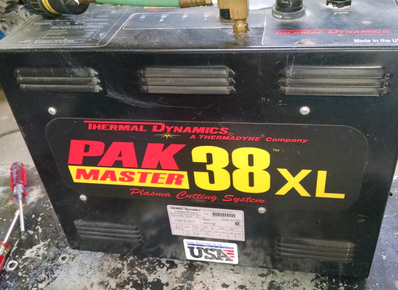
08/04/2016 at 03:09 • 0 commentsThe plasma cutter that is being used for this table is Thermal Dynamics Pak Master 38XL. From what is found online it is a high frequency start (read electrically noisy) cutter.
![]()
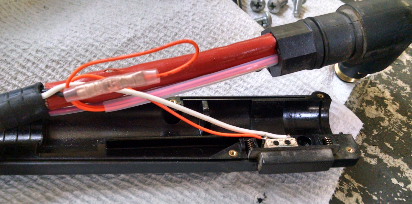
The handheld torch has a NO trigger that simply closes a circuit back at the main unit. In the picture below the black and white wire coming out from under the sheath is the fire command. The black wire connects to an orange wire that feeds out to the torch head's PIP (part in place) connection. A second orange wire feeds back to the NO trigger.
![]()
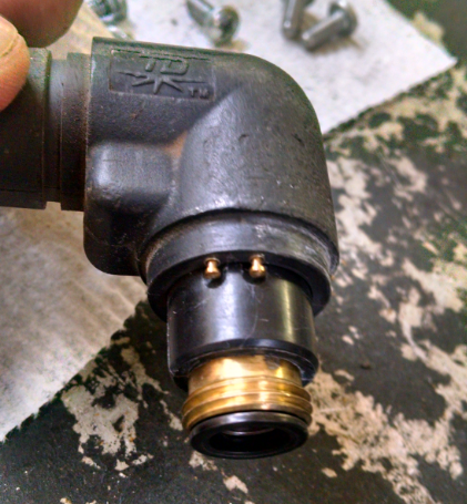
Below is the PIP contacts that detects that the tip cover is attached.
![]()
The CNC will bypass the PIP circuit and act only as a basic fire. A relay was placed back in the main unit that connects the black and white wire together.
![]()
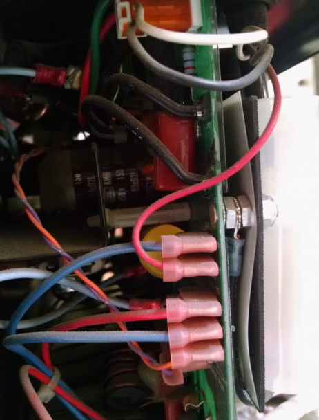
In the picture below, the upper white and black wires are the torch fire circuit and the red wire is the main cutting circuit to the plasma torch.
![]()
The firing circuit was spliced and the wires fed to the NO contacts of the relay.
![]()
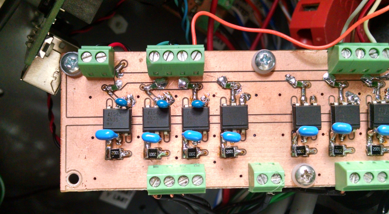
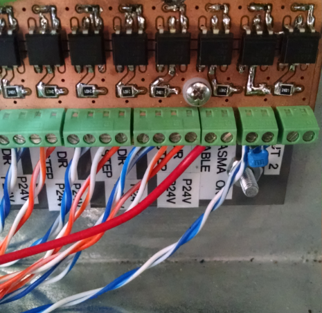
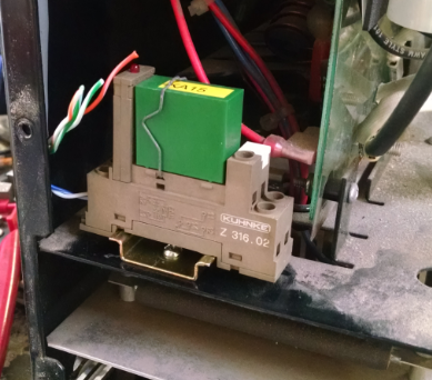
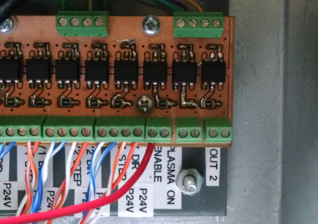
A 24V relay was chosen since the opto coupler output card in the controller box uses 24V. The card was modified as a direct short to 24V with the relays coil as the load. The second from the right opto has the output resistor removed and the pads were solder bridged together.
![]()
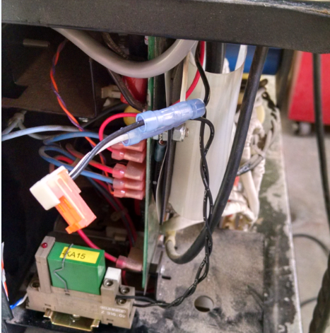
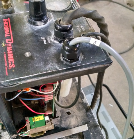
A strain relief was added to the top of the plasma unit for cable routing.
![]()
-
Stepper Drive Enclosure
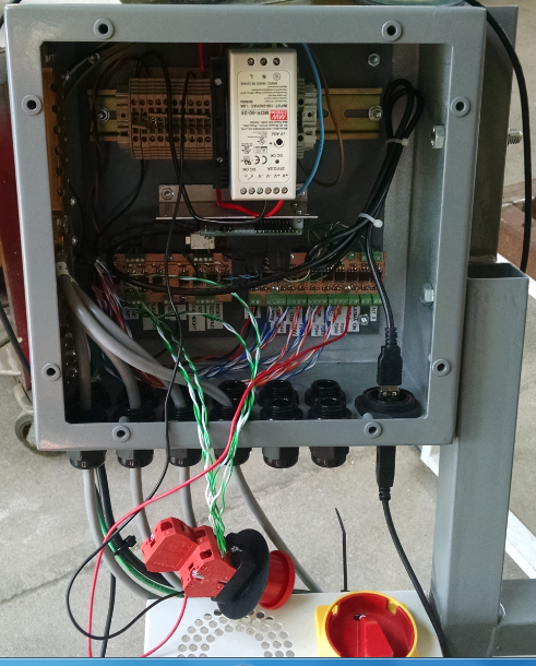
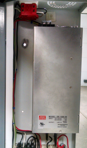
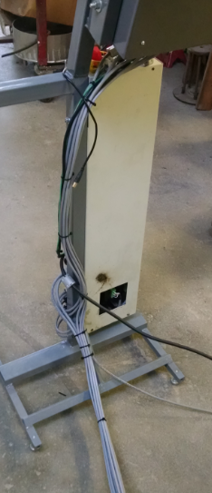
08/03/2016 at 02:57 • 0 commentsThe Stepper Drive enclosure is separate from the controller enclosure. It started life as a heater controller that had something to do with commercial printing. It was sourced from the same place as the printer used as the Y axis gantry. The stepper power supply is a 48V MeanWell. 220V is fed in on the top side from the power switch. (fuses are in series between the switch and the power supply)
![]()
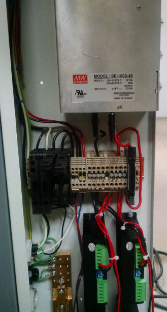
This feeds a terminal strip that breaks out to the four stepper drivers. (a fuse is in series between the power supply output and stepper drivers)
![]()
The photo above is early pictures that does not include an estop circuit that disables the stepper drivers. I am a bit concerned that the enable input on the stepper drivers is active high to disable. I would rather it be active high/low to enable the drives. So if power is lost to the input, they would shut down. Lesson learned on using M452's. The terminal blocks were sourced from another industrial controller box that was going to be thrown away.
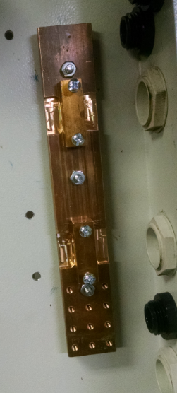
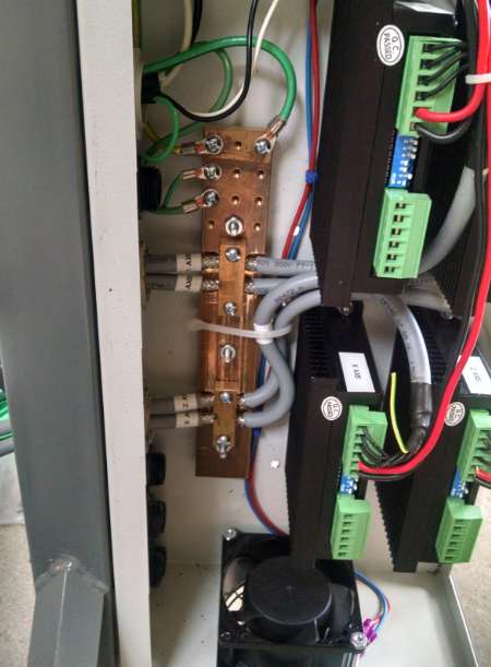
The ground bar to the left acts as the main safety ground and as a sink for noise as the shielded cable is fed into the box.
![]()
![]()
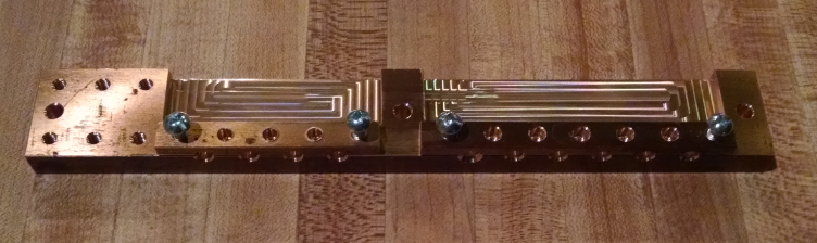
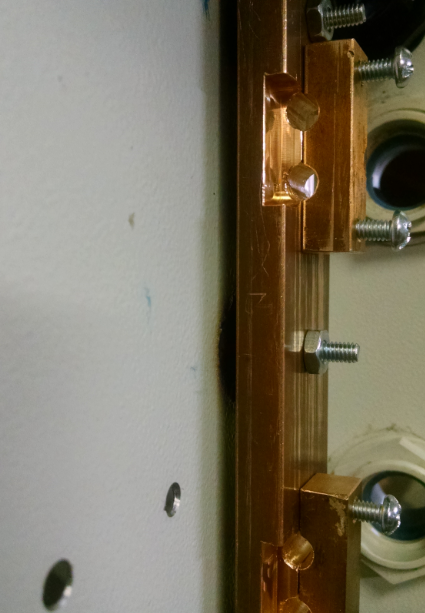
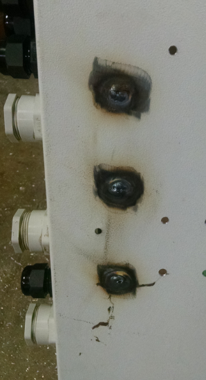
The shielded cable is fed through the clamps with the shield exposed. The screws clamp around it to drain any noise that could be coming from the outside. The brass bar stock for these were used as door handles prior to being machined and repurposed as the grounding bars. The three studs that stick out to clamp the ground bar to the enclosure are welded on from the backside.
![]()
Below is a pic of the stepper cables being fed through the ground bar.
![]()
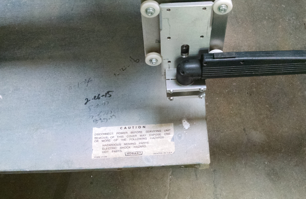
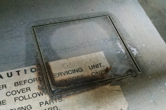
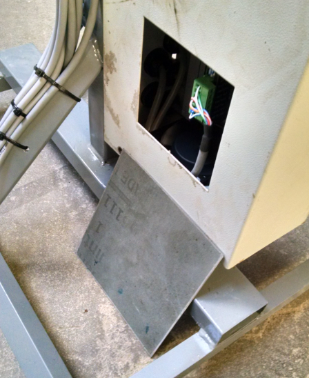
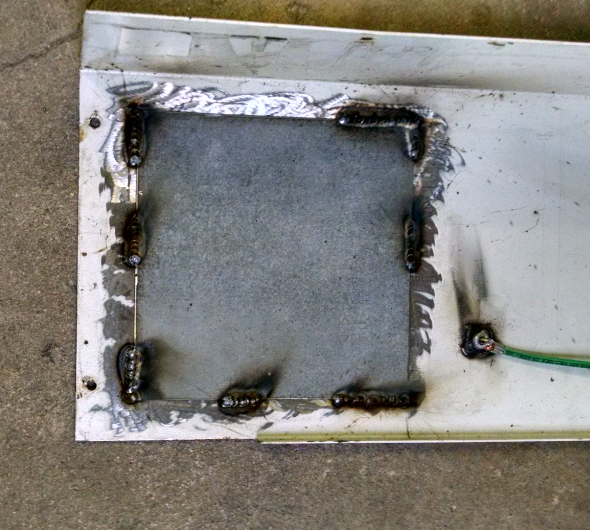
The cover to the enclosure originally had a window for the controller interface. This was closed up with some scrap steel that was cut with the plasma table.
![]()
![]()
Also seen in the above photo is a ground stud that ties the ground bar to the enclosure cover.
-
Cable Routing
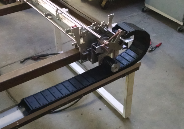
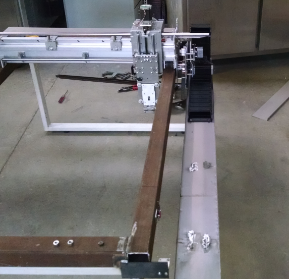
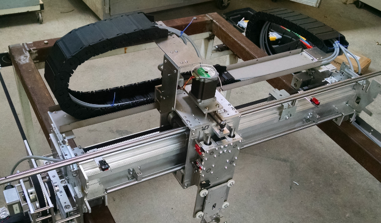
08/02/2016 at 02:43 • 0 commentsCables were routed between the controller box and driver box to the steppers and limit switches using enclosed IGUS cable carriers. The Y axis carrier carries the bulk of the cables while the X axis carrier is considerably less.
Mocking up the cable carriers was roughly done with kant twist clamps.
![]()
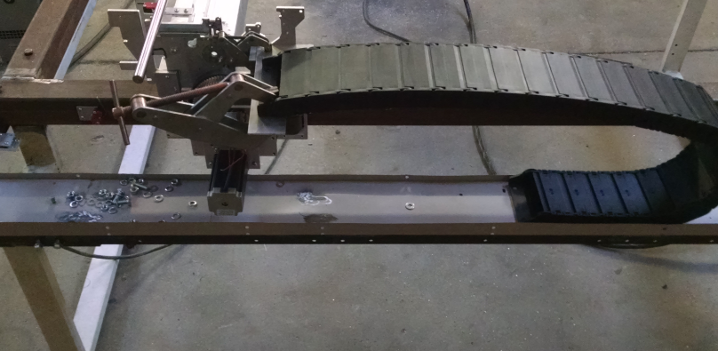
The tray that the carrier sits in for both X and Y axis was sheet metal taken from some high school lockers that were being thrown away. They were cut using the handheld plasma cutter that is now used on the CNC. To bend the 90 degree angle lip, some long angle iron was used.
![]()
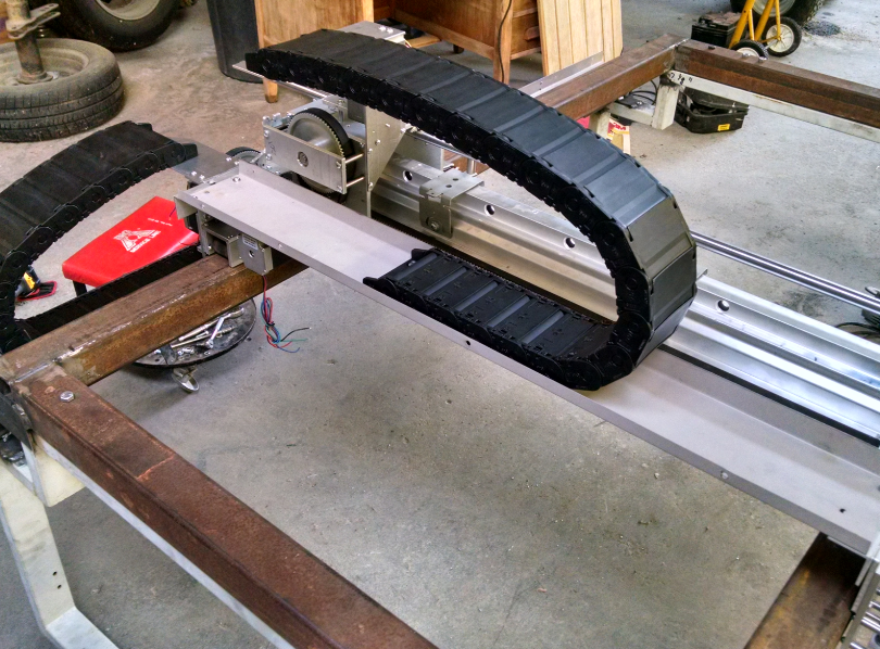
The tray was held up using some angle iron that was pulled from a bed frame. Once satisfied with the location, the carrier was fastened to the tray and carriage.
![]()
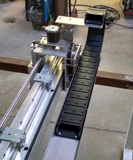
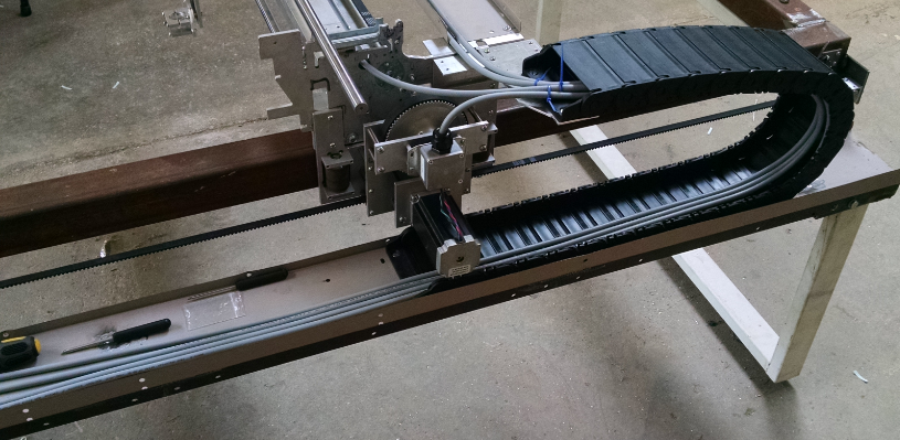
Below are a few pics of the installed x axis carrier.
![]()
![]()
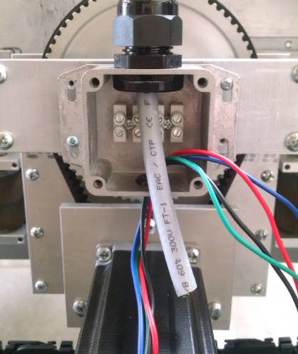
The Stepper motor wiring was then wired through. Some 5 conductor flex shielded cable was used. The fifth wire was abandoned since 4 wire bipolar steppers were used.
![]()
![]()
The stepper wiring was terminated in small diecast cases that had a terminal strip.
![]()
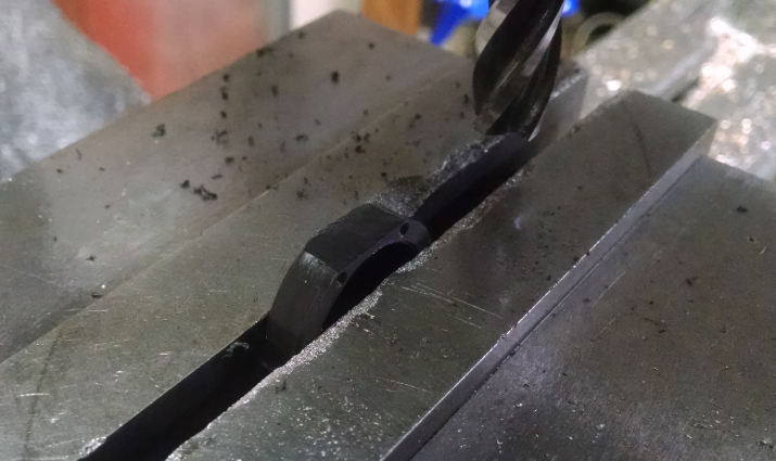
The strain reliefs barely fit into the side of the enclosure and required the nuts to be modified. Flats were machined for clearance for the bottom and lid of the enclosure.
![]()
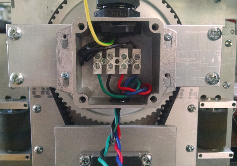
The stepper wires then were terminated on the terminal strip.
![]()
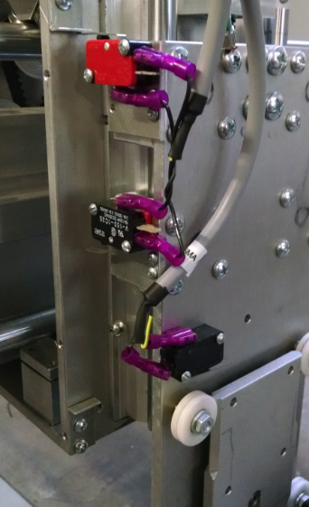
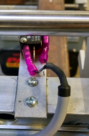
The limit switches were installed for both sides of travel on each axis. The Z axis had a third limit switch installed to act as the floating head detect.
The axis limit switches were wired in series and utilized the NC connections. One of the X axis limits shown below.![]()
![]()
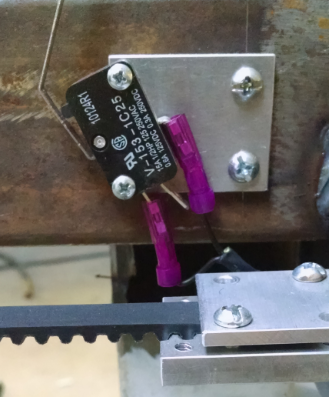
And the Y axis.
The cables were then routed into the controller and driver box.![]()
![]()
![]()
-
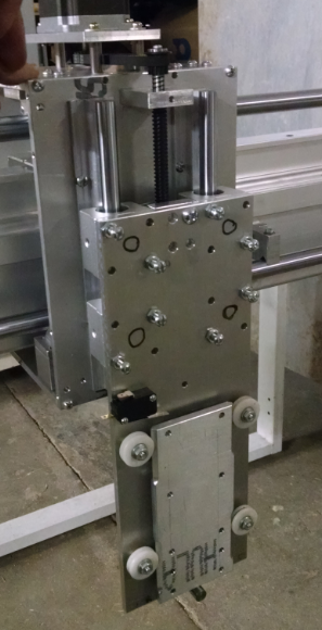
Z Axis
07/28/2016 at 11:35 • 0 commentsThe Z axis deviated from using the motors used on the X and Y axis. Instead a motor that was pulled from some random copy machine was used. The linear guides are some that were bought off of ebay coming from China. Not sure if I will go this route for the next generation of cnc anything, but for a cheap route, they work.
![]()
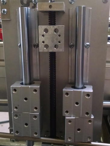
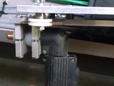
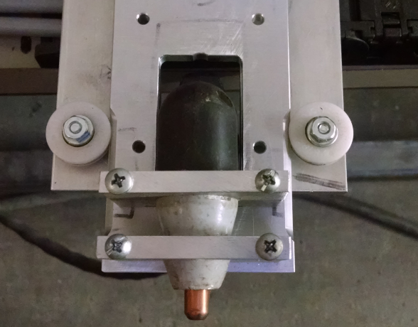
The lead screw is two start 10 tpi. Which means the lead is 5 tpi. The plasma gun attaches to a floating head the rides on some plastic bearings that was pulled from (I think) a typewriter. The edges of the plate were chamfered to create a peak that would right in the v notches of the plastic bearings. Located at the center of the floating head, stroke was limited by a hard stop captured inside of a slot.
The switch on top is used as the touch probe for initial torch height touch off. This design works great for small designs when the machine does not require 4x2 ft travel. But when a 4 ft sheet needs to have an exhausted piece of material removed that has been cut 2 ft wide, there won't be enough travel. The initial intentions were to design for a straight machine torch instead of a 90 degree hand torch. Seeing that is probably not in the near future, the handle will be moved to point under the x/y carriage.![]()
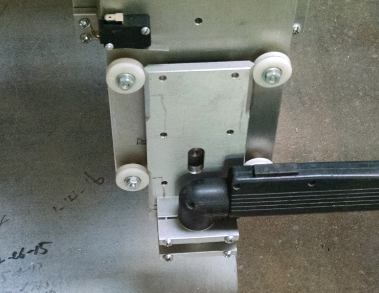
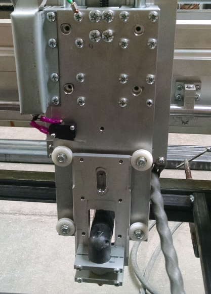
The Z axis plate was removed exposing the linear guides.
![]()
The plasma mounting was looked over.
![]()
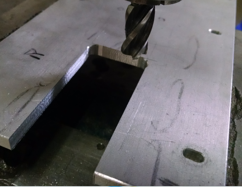
The hard physical limit (not switch) will have to be moved up 2 inches and the plates will need to be slotted to allow for the handle to stick underneath the carriage. Starting with the main plate, the corners were drilled and a band saw rough cut the material out. An end mill in the mill/drill brought the slot to size.
![]()
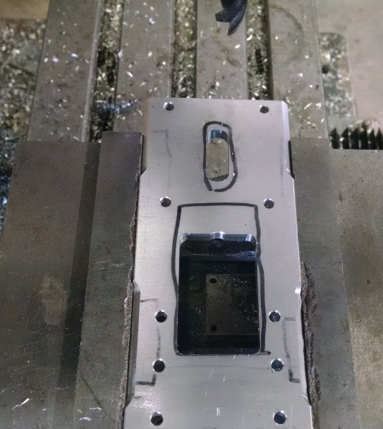
The floating head plate then needed similar treatment. The hard stop slot was shifted up 2" and a 2"x1.25" slot was added.
![]()
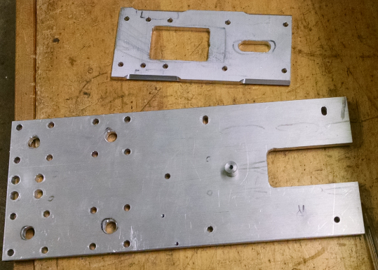
And the finished parts ready for assembly:
![]()
The parts were assembled to try fit the plasma torch floating head travel. The mechanical limit hits before the torch itself hits the slots edges.
![]()
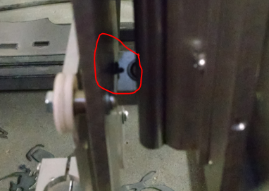
So far so good. This assembly was then placed onto the linear guides and travel was tested. The screw head on the back ended up hitting the lower lead screw bearing. So the screw hole was counterbored until the travel was unlimited.
![]() The cable for the torch was the next concern. It had to stay out of the x axis travel from being pinched. Some aluminum cable clips were modified to fit. The picture below shows them on the left and right.
The cable for the torch was the next concern. It had to stay out of the x axis travel from being pinched. Some aluminum cable clips were modified to fit. The picture below shows them on the left and right.
![]()
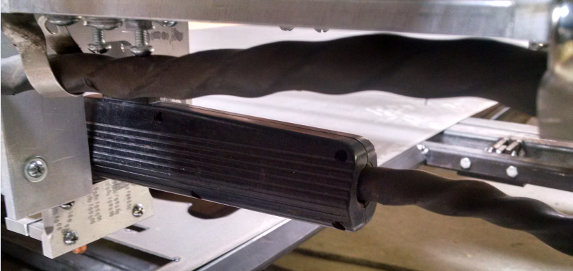
And the completed modification:
![]()
10/2/16
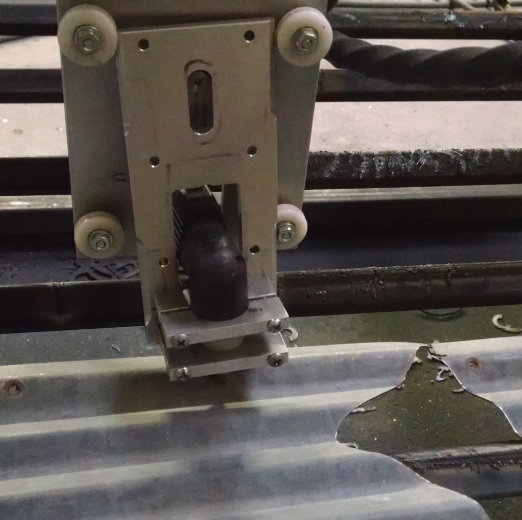
Floating Head Crash. After successfully cutting a part out of corrugated tin, I wanted to cut the exhausted material from the larger sheet to continue cutting other parts. The Torch was sent in rapid over to the cut location and caught the corrugated tin that was clamped to the table. This popped the floating assembly out of the tracks. cracking the upper left v groove.
![]()
The screws were loosened and the assembly remounted. Even there is a cracked v groove, it still functions. There is definitely a need to standardize what coordinate system does what. Possibly:
- G54 - use for material cut. This will locate the x y cut locations.
- G59 - use as table home location for x and y.
Can then raise the torch to z -1 height (top of the stroke is 0) when traveling between cuts.
So something like this:
- G59 home machine on startup and as needed if there is assumed missed steps
- Move to xy zero of cut using G91 incremental mode
- G54 zero out x y location to new location using G10P0L20X0Y0
- Make cut (Start up part program)
G59G92.1 (to cancel coordinate offset) raise to z 0G54move to next location within part program- At end of program, G92.1 to cancel last coordinate offset.
- Stop Part Program
Will have to look into CamBam - MOP to setup routine in the post processor.
-
X Axis
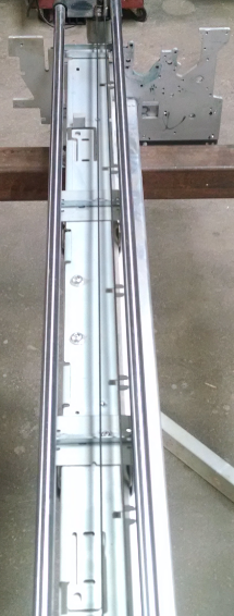
07/28/2016 at 11:21 • 0 commentsThe X Axis linear guides started life as an industrial printer. The rails sat on what is now the top of the printer chassis.
![]()
The picture shows the original belt drive. It used a DC motor like many other printers and moved the plastic print head mounted to plastic bearings. This allowed some movement in directions that were more than my liking. So at the very least, the carriage bearings were needing an upgrade.
![]()
The rail design was changed by moving the back linear guide down in front of the chassis. The guide had to be cut down. The material was not hardened (which means wear will play into bearing contact at some point) so a horizontal band saw cut off the excess.
![]()
To hold the rail in its new place, some mounts were made from aluminum. The rail already had some holes drilled and tapped from the original configuration, so they were utilized.
![]()
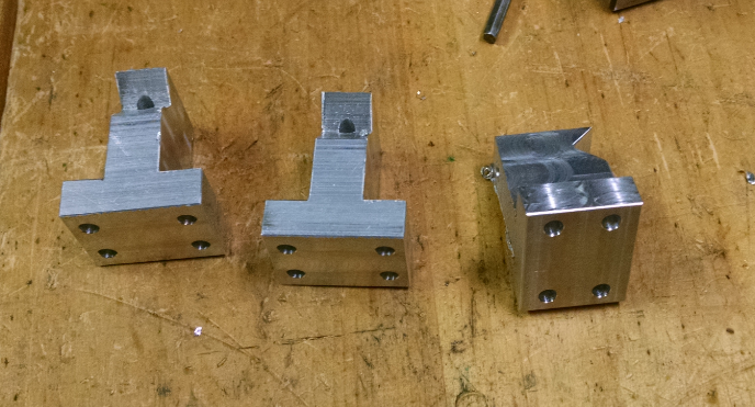
Before the rail could be mounted, the X axis carriage needed to be built. Along with this the new bearings. Using more bearings from copy machines, they were attached to some peaked blocks that would allow the bearings to form a v. Many linear guide configurations have used similar v designs.
![]()
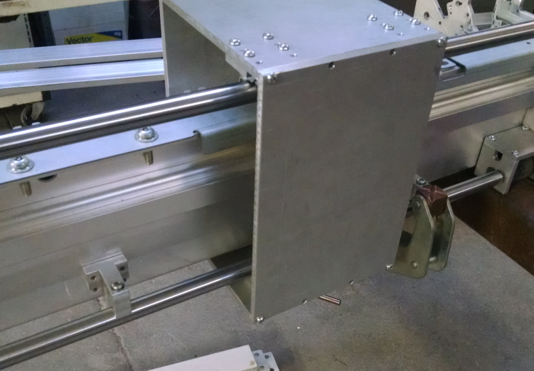
The X carriage forms a box that surrounds the printer chassis. It is made from 4 aluminum plates and will allow for the x and z motor assembly mounting.
![]()
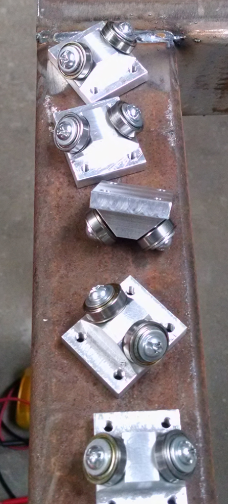
There are four bearing blocks that are used in this axis. 2 are fixed at the top as can be seen by the screw heads. 2 are floating along the bottom. IE, they are adjustable front to back and top to bottom. This allows fine tuning of the bearing to rail clearance.
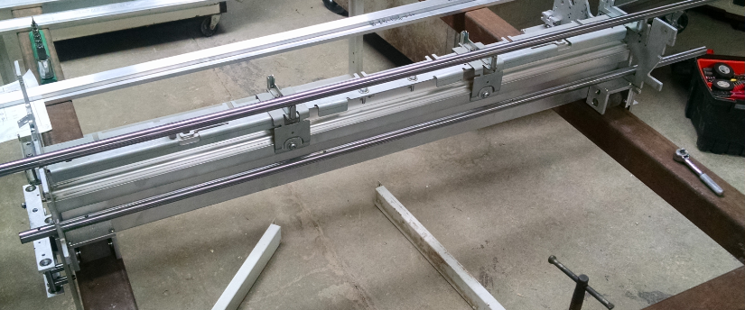
The rail was then ready to be mounted. Installing all four bearing blocks (the bottom two in the middle of adjustment travel) the rail was clamped to the chassis. A 6" micrometer was used to measure the distance between the rails.
![]()
The final assembly included some spacers between the x carriage and bearing blocks that the above picture does not show. The spacers were added due to maximum micrometer size for measurement between the rails. But the idea is there on how the rails were clamped for installation. Below is the picture of the mounted rail.
![]()
This configuration did not allow for a consistent distance between the rails that was satisfactory. So the linear mounts had the holes slotted to allow for adjustment. Jack screw blocks were also made that attached below the linear mounts. I couldn't find pictures, if there is interest, I will try to get them posted.
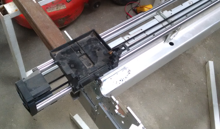
The X axis motor assembly using the same motor/pulley configuration as the Y axis.
![]()
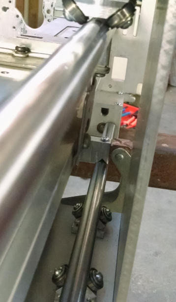
The big difference is placing another bearing surface to ride on the printer chassis. Since there is a lot of weight on the side of the motor and the x axis box carriage is springy, some method needed to contain the movement.
![]()
The fourth wheel that is opposite the drive pulley is the bearing. this rides on the printer chassis. It is aluminum on aluminum, so at some point, galling will show up. Using a plastic bearing might come into play in the future.
The belt clamps were mounted to either side of travel. The adjustable belt clamp did not see as much tilt as the Y axis. Attributed to moving the screw holes closer to the belt.
![]()
![]()
-
Y Axis
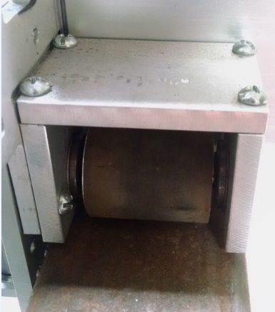
07/27/2016 at 02:53 • 0 commentsThe Y axis linear guides do not use the plastic wheels of the original design. They now use rubber coated wheels. The wheels were made from a couple of rollers that were cut down. The ends were faced off to length in the lathe with a center hole opened up by boring out to allow for an interference fit on short segments of shafts (again from copy machines). These then ride in bearings that were also pulled from copy machines.
![]()
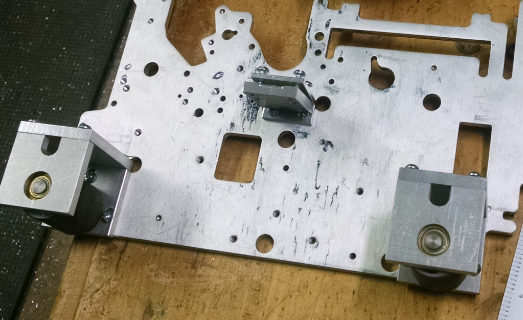
1/4" aluminum plate was used throughout this build and were also used in making the roller wheel carriages shown above. To contain the carriage, multiple rollers were used. Fixed top and side rollers were used on one side of the carriage.
![]()
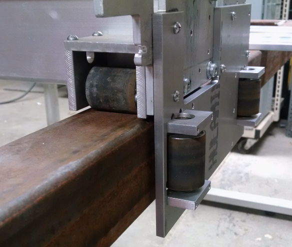
While the other side had a single spring loaded roller to maintain the carriage shifting left and right. In the picture below, the spring is on the left side and the fixed rotating axis of the lever is on the right. This is not a solid method to keep the X axis square with the Y axis travel. It gets by for now.
![]()
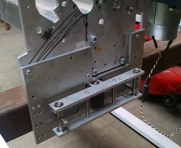
The carriage does not have rollers on the bottom to capture up and down movement. For the cuts that have been taken, the carriage weighs enough to hold it down on the steel tubing. At some point this should be updated to prevent creeping up of the carriage.
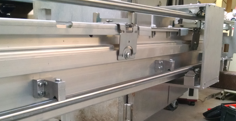
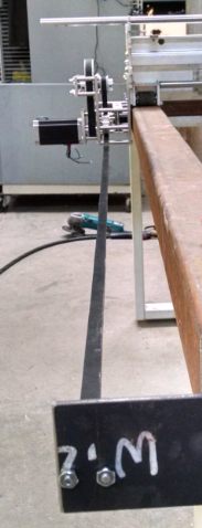
Now to the drive mechanism. Looking around the net shows that rack and pinion is the choice to use for CNC table anything, router, plasma, name your cut. Being concerned with price/mounting of the rack on the bottom, I opted for drive belts.
![]()
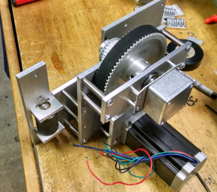
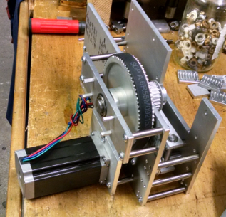
The carriage is driven on both sides to prevent large amounts of skewing of the X axis. Both sides use the same pulley ratio (3:1) prior to driving the linear belt. The way that the drive assembly mounts varies from side to side. Focusing on the right (left?) side.
![]()
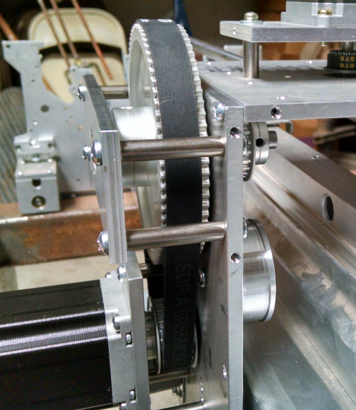
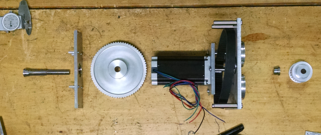
The stepper uses a 24 tooth pulley that drives the 72 teeth pulley above. The 72 teeth pulley is tied to a shaft that drives another 24 tooth pulley. The upper shaft can be seen above.
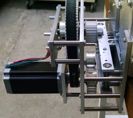
![]()
The picture above shows the upper shaft assembly spread out. Starting on the left is the shaft that feeds through the first bearing feeding through the 72 tooth pulley. Then feeds through the second bearing. A spacer is used on the second bearing to make up the gap between the shaft and bearing. Finally the drive 24 tooth pulley slips over the shaft. The pulleys are both fixed to the shaft with set screws. The shaft has flats milled where the set screws push against.
The picture above shows two idlers barely peaking out to the right of the motor. These slip over small shafts for the bearings to mate against.
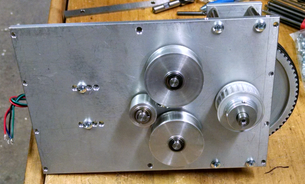
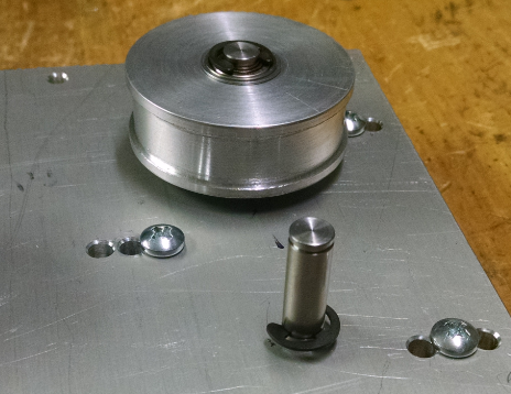
![]()
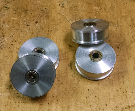
The idler pulleys were made from aluminum round. They were turned and faced to size. The center was opened up for an interference fit for two bearings on either side of the pulley.
![]()
Here are a couple more pics of the assembly.
![]()
![]()
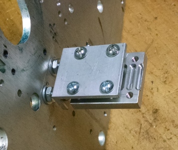
The belt tension adjustment between the motor and pulley is allowed by slots in the motor plate.
![]()
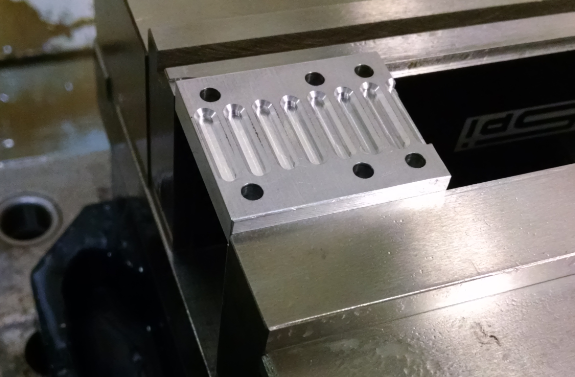
Mounting the cut belt on either side of the table was done by milling slots into a piece of aluminum at the pitch of the belt. This plate was mounted to a piece of angle with the belt sandwiched between.
![]()
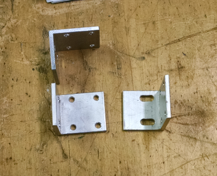
![]()
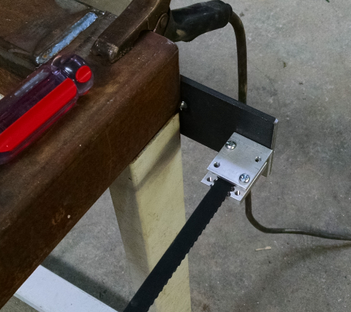
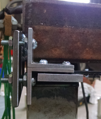
One belt clamp side is adjustable and the other is fixed. The fixed side worked good since it positively contacted the frame.
![]()
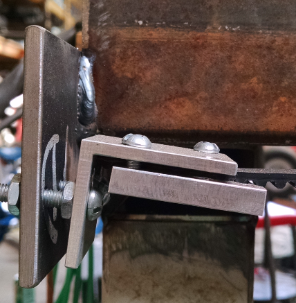
The adjustable side had issues with sitting at an angle.
![]()
An upper angle piece was made to help pull the angle to 90 degrees with the frame plate.
![]()
-
First Frame Design
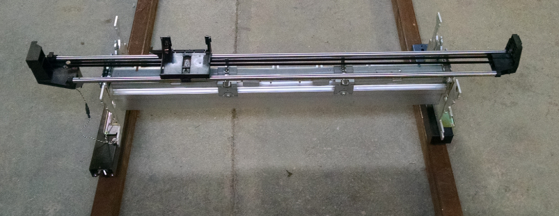
07/27/2016 at 01:28 • 0 commentsWhen I first started this project I wanted to keep the build as cheap as possible. So I started to reach for anything that was already at my disposal. This meant using steel square tubing on hand and printer parts. The x axis was an industrial printer that was being tossed due to the company going out of business.
![]()
This has been in storage for a few years waiting for a project to be used on. It is not as much travel as I would really want (5 ft) but will work for now. The original design was going to utilize wheels that were off of a side paper attachment of a copy machine. Similar to the one that is being used on the 3D printer build (put aside for this project, but not forgotten).
![]()
![]() The old design was also going to use some wire cables. They might have been from a volleyball net, but do not remember for certain.
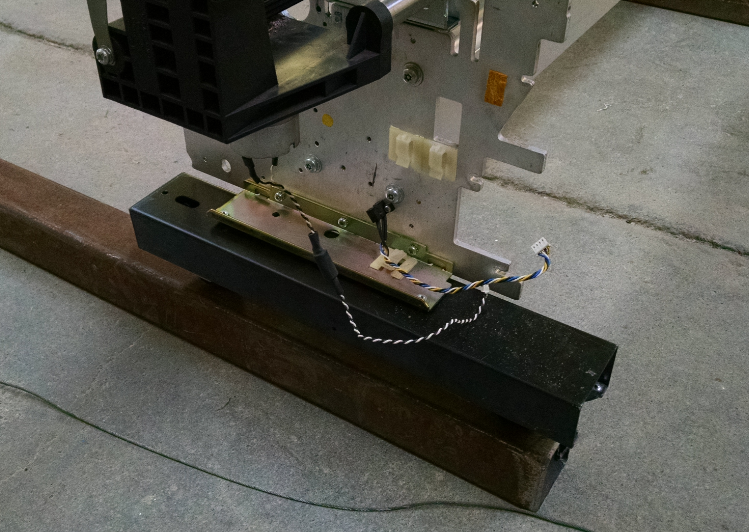
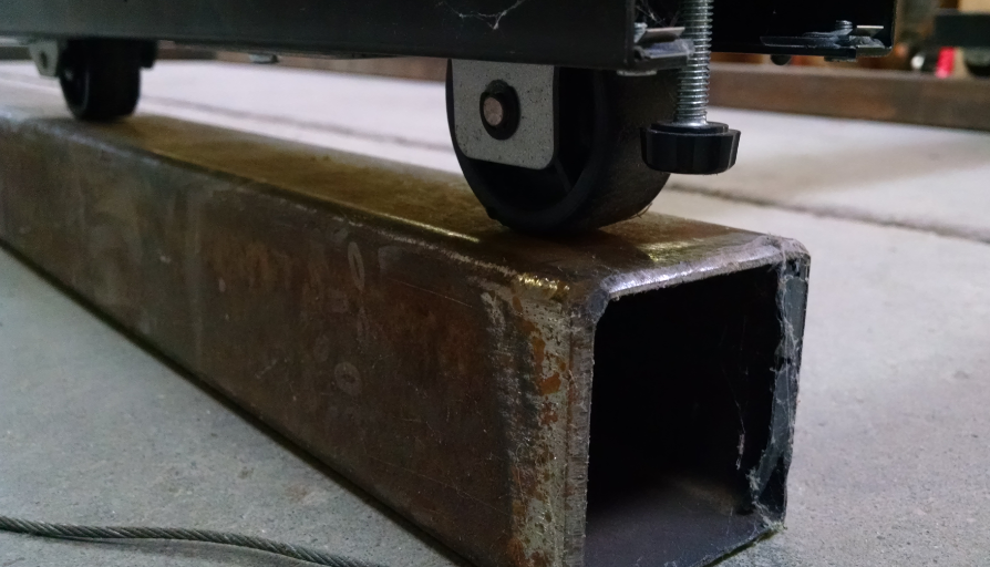
The old design was also going to use some wire cables. They might have been from a volleyball net, but do not remember for certain. ![]() The Printer was going to sit on top of the wheels that would ride along the top of the steel tubing.
The Printer was going to sit on top of the wheels that would ride along the top of the steel tubing.![]() The white stands in the picture also came from the printing business. This held up another machine that I don't remember what it was for. Sitting in storage just as long as the printer. These are to hold up the frame of the motion of the plasma table. The shafts on either side of the frame were also from the same printer. They were going to be used to pull the cable back and forth.
The white stands in the picture also came from the printing business. This held up another machine that I don't remember what it was for. Sitting in storage just as long as the printer. These are to hold up the frame of the motion of the plasma table. The shafts on either side of the frame were also from the same printer. They were going to be used to pull the cable back and forth. The design then changed.
CNC Plasma Table
Plasma Cutter + CNC Table + Auto Load/Unload = Tool to build other projects faster
 Still had the issue with the hard limit. Along with the hard limit issue creeping in, the relay that turned the plasma torch on and off was not firing all the time or was firing and then immediately shutting off. So a 100 uF cap was added to the 24V power in on the output card and a .1 uF cap across the plasma gun on output.
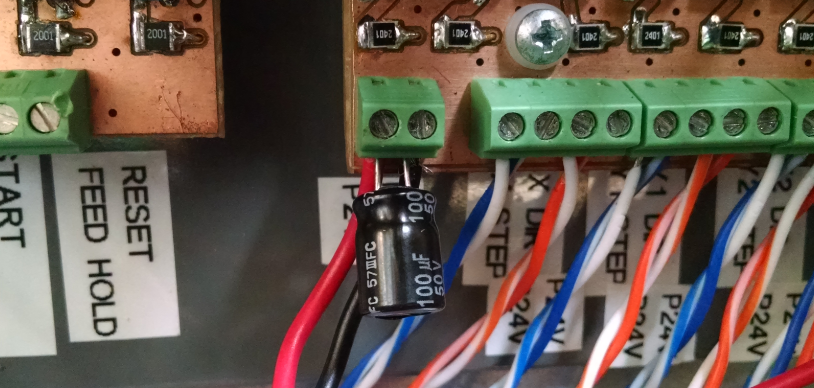
 The cable for the torch was the next concern. It had to stay out of the x axis travel from being pinched. Some aluminum cable clips were modified to fit. The picture below shows them on the left and right.
 The old design was also going to use some wire cables. They might have been from a volleyball net, but do not remember for certain.
 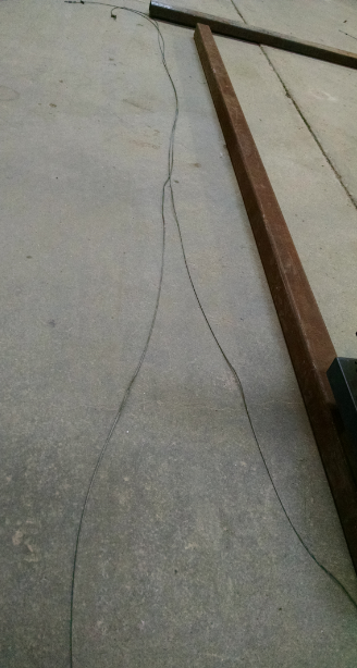 The Printer was going to sit on top of the wheels that would ride along the top of the steel tubing.
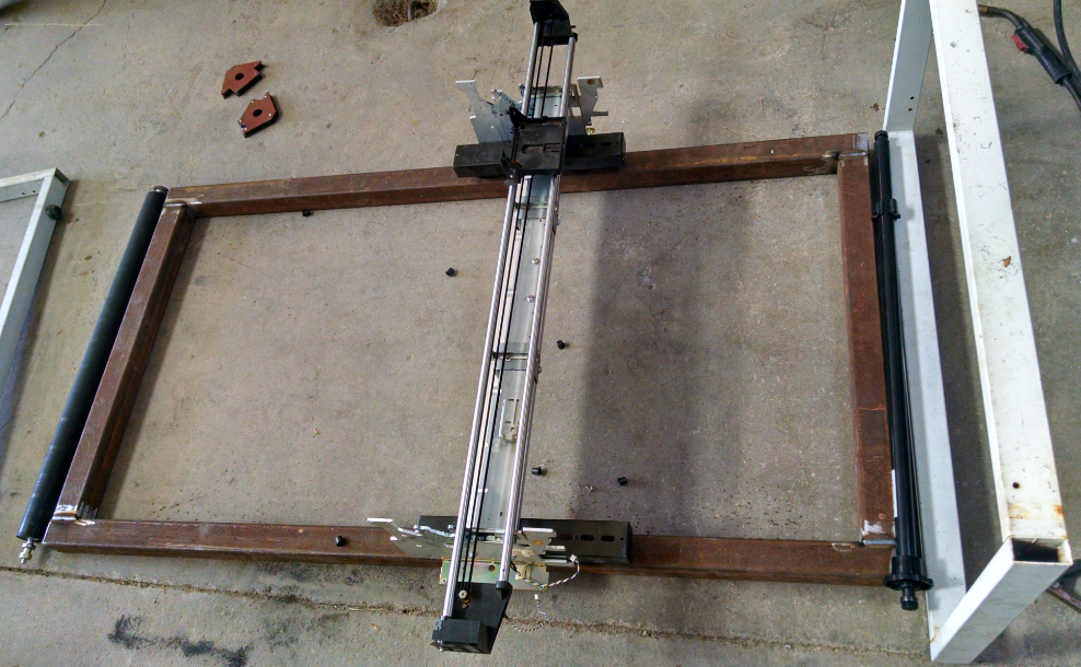 The white stands in the picture also came from the printing business. This held up another machine that I don't remember what it was for. Sitting in storage just as long as the printer. These are to hold up the frame of the motion of the plasma table. The shafts on either side of the frame were also from the same printer. They were going to be used to pull the cable back and forth.