forthnutter
-
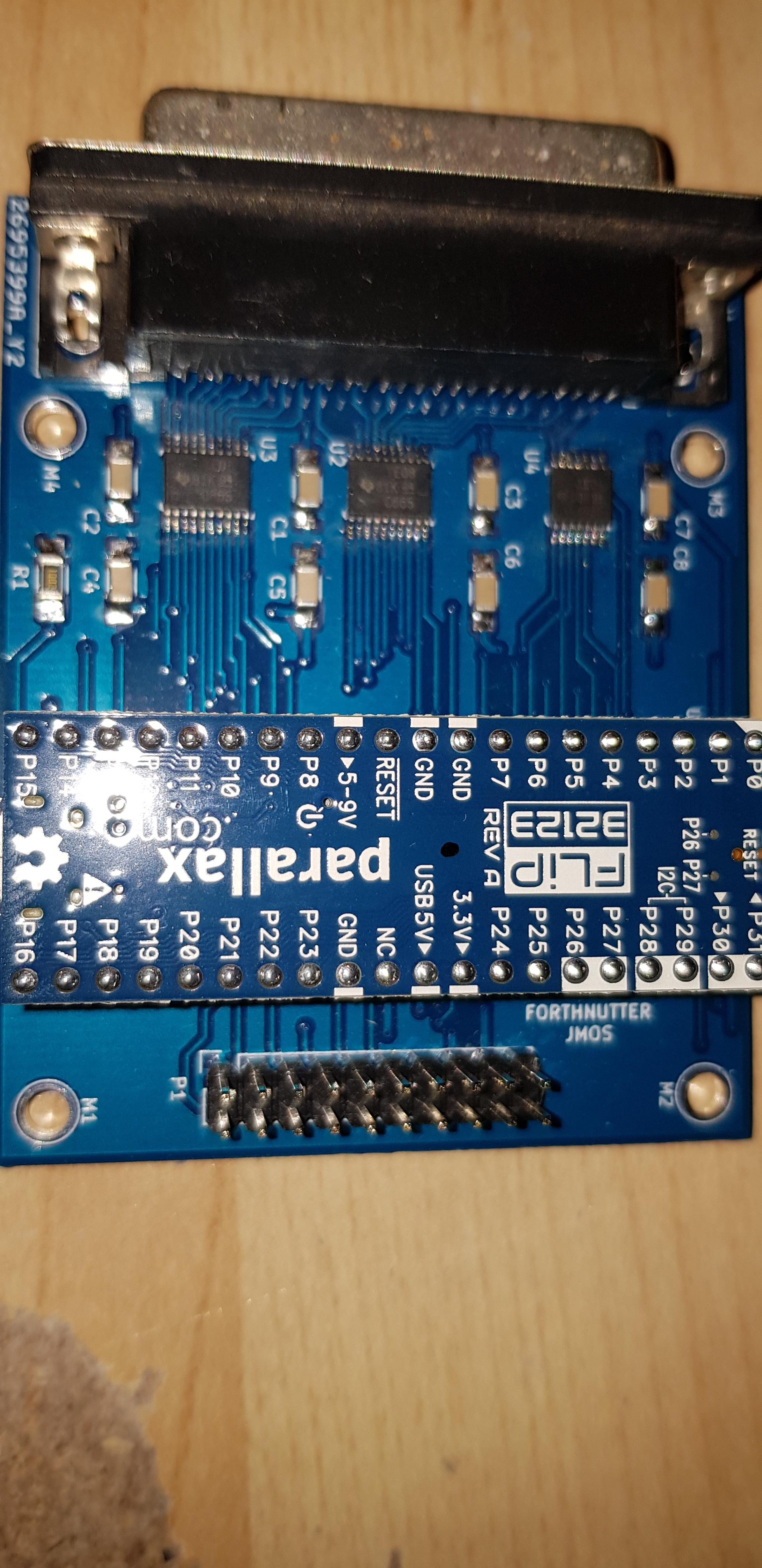
First Prototype PCB
09/16/2019 at 15:09 • 0 commentsI did quick PCB in KiCAD, Using Parallax Flip PCB. With some level shifters going to DB 25 Printer connector.
I am really like these Flip board for making prototypes easy. Depending on the circuit you can utilise the power coming from the USB. Also have access to 3.3V.
The design for this PCB can be found on my bitbucket on this project page.
![]()
-
After all that, looks very simple
08/06/2019 at 12:49 • 1 commentOnly spent a couple hours this part and look like very simple glue logic. Only difficult section was the compare logic done earlier.
I think I am going to need to test this, by designing some logic equations and put it into a PAL Assembler. Now I wonder where I can get a PAL Assembler now days.
Going through my stock of old part in garage. I found a tube PALCE22V10, now how do we program the little chippies.
Need to dig out that old Universal Programmer I packed away in a box.
![]()
-
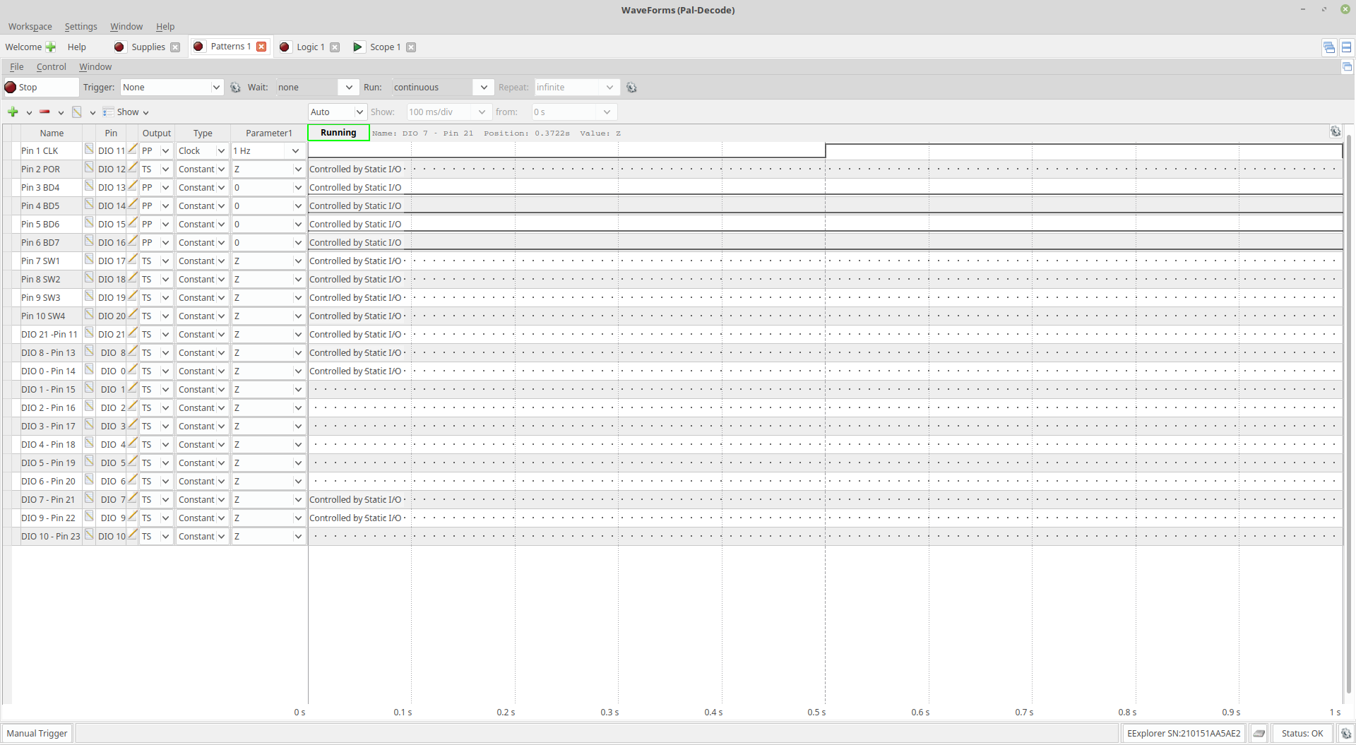
Setup a clock signal
08/06/2019 at 12:18 • 0 commentsI have setup a 1Hz clock signal to pin 1 to see what output pin are latched.
![]()
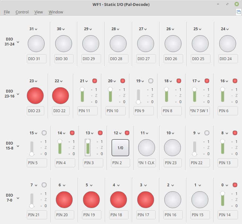
Then toggled the input on the Static I/O screen to see what changes and signals that changed on the clock edge.
![]()
-
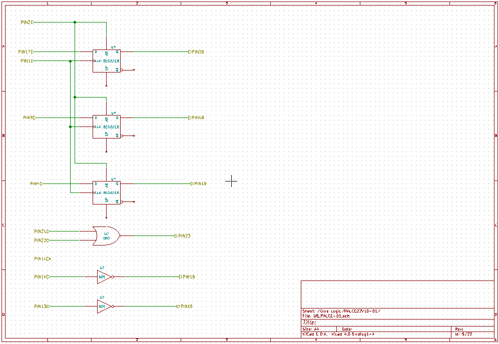
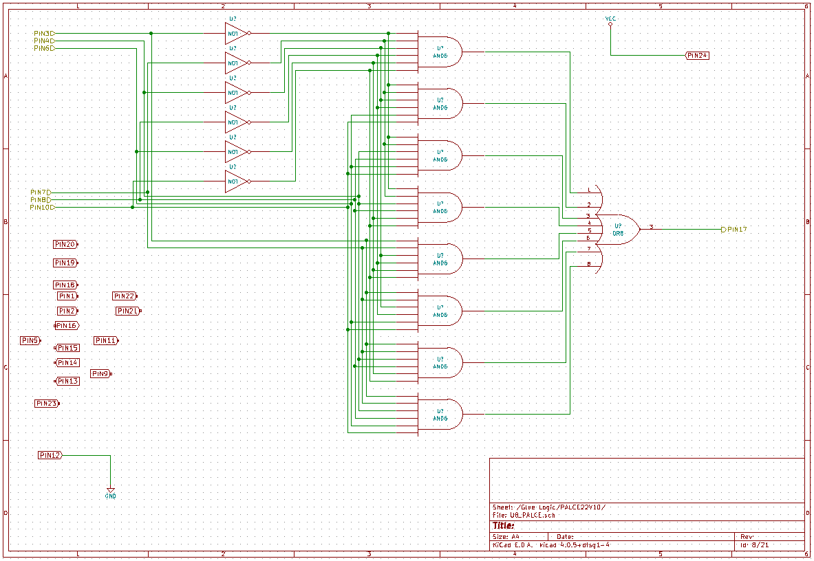
Focus on output Pin 17
08/02/2019 at 23:44 • 0 commentsI have been focusing on Pin 17 it looks like a select pin that is latched externally and seems to only change by pins 3,4 and 6. Also by the links on pin 7,8 and 10. I am thinking its compares the links with 3,4 and 6. Odd thing pin 5 and pin 9 do not have any effect, but is included in circuit. Picture below is quick circuit of Pin 17 output.
![]()
-
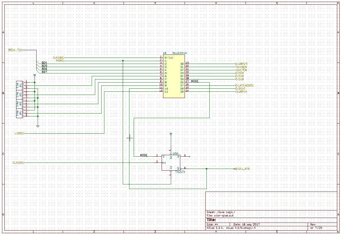
Setting up the Pins
07/28/2019 at 09:11 • 0 commentsThe re-engineered circuit shows the PAL has 15 physical inputs and 7 outputs. It looks like some of the outputs of the device are configured as inputs.
![]()
-
Setting up Power
07/12/2019 at 14:36 • 0 commentsSetup Power for the PAL and the Level shifters.
![]()
-
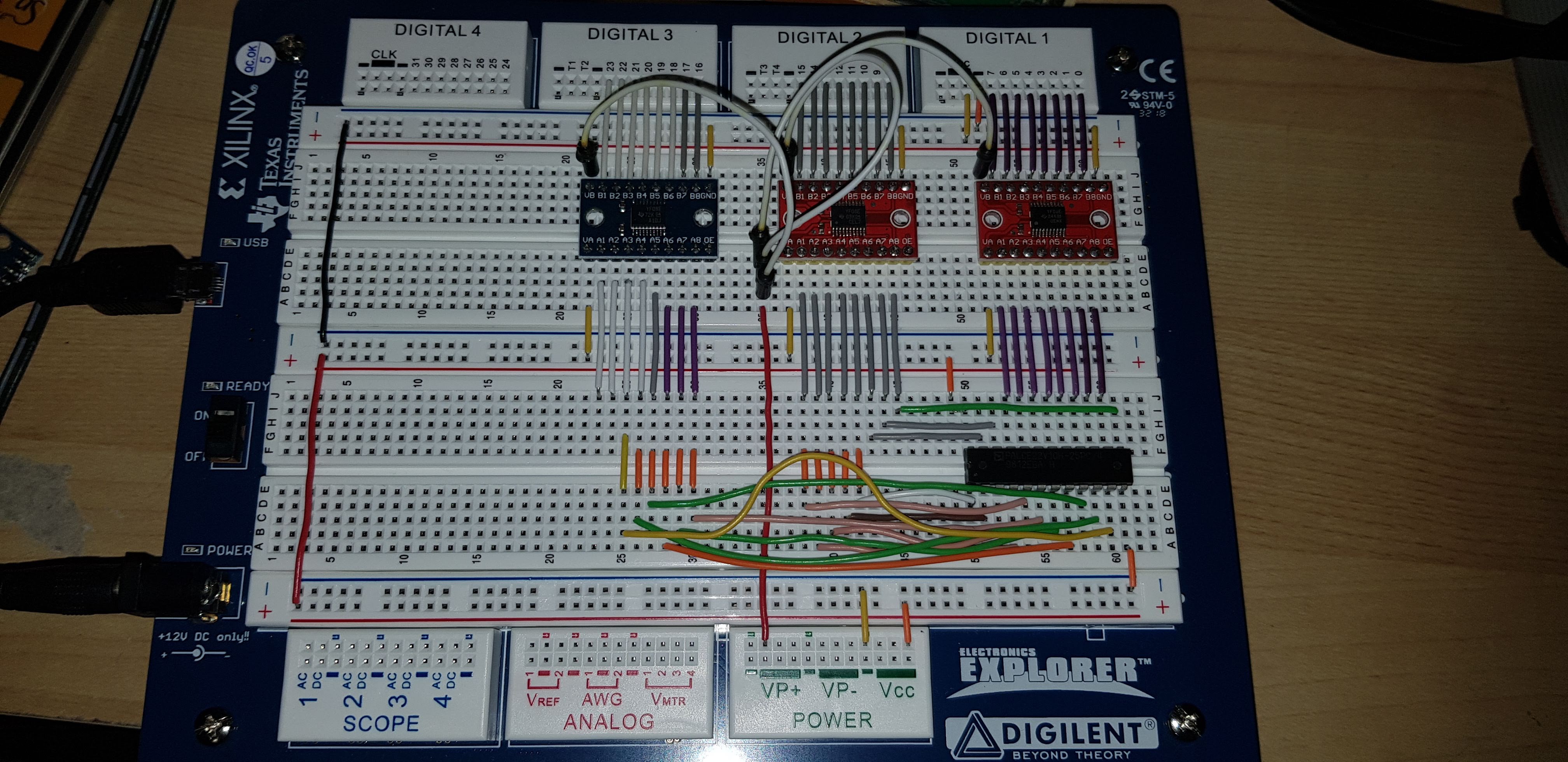
Reverse Engineer a PALCE22V10
05/20/2019 at 13:08 • 1 commentNumber of ways to Reverse Engineer a PALCE22V10.
Decided to remove the PAL from PCB and put on my "Electronics Explorer" from Digilent.
Wired in some level shifters so I can run and drive the PAL inputs at 5V.
The 10 output pins wired to lower 10 bits of EE Digital ports and 12 bit of the rest of EE Digital ports go to the inputs of PAL.
So now I can toggle each input and read the output to see what does what.
![]()
-
PALCE22V10
04/18/2019 at 11:02 • 0 commentsThe WICE-4M has a PALCE22V10 on PCB some kind of "Glue Logic".
Attempted to read the device on a "Hi-Lo All-3A" Programmer, yep the security fuse is blown.
Looks like I will have to do this the hard way.
-
Need more steam
03/20/2018 at 13:09 • 0 commentsThis project has slowed down, mainly concentrating on get the firmware working, no hardware design yet.
Need to boil up some more steam to get things moving.
-
Stack Based Firmware
12/17/2017 at 06:33 • 0 commentsBuilding the firmware in MPLABX
Everything is in 18F Assembly.
First started building MACRO's to make a data stack words.
So we have a kind of forth style words.