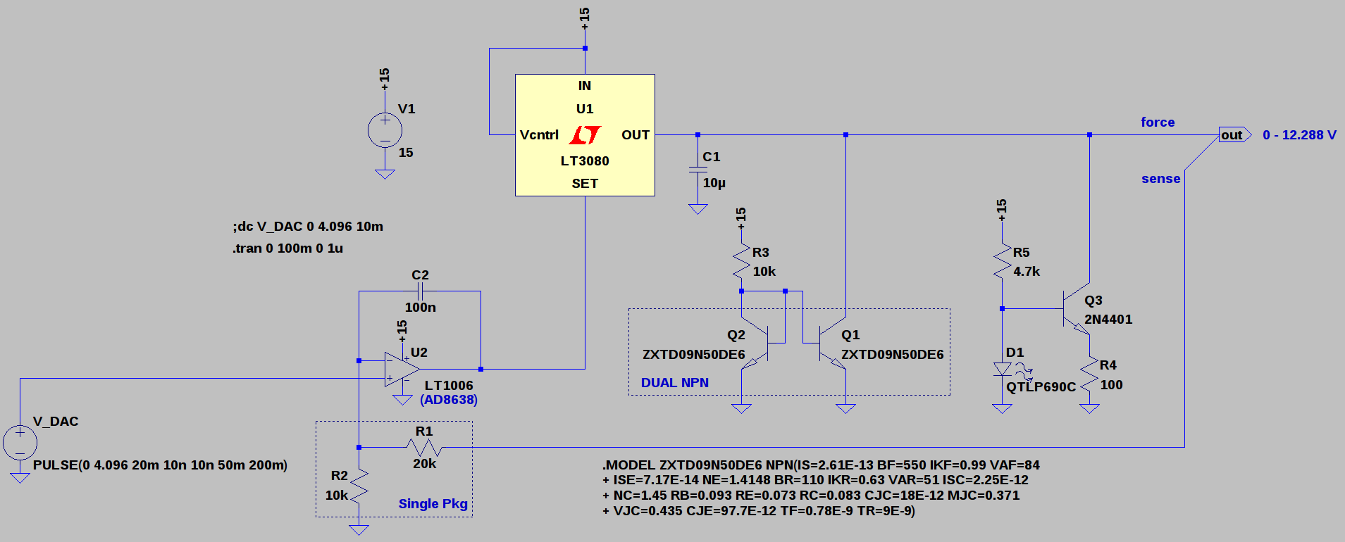
I re-designed the programmable voltage source used in the analyzer; the new version could easily find use as a general-purpose computer-controlled lab supply. Here's a simulation of the back-end, ignoring the DAC and voltage reference for the moment:

The first prototype used a 10-bit DAC driving an LM317 to produce a 1.25 - 13.54V supply with a 12mV/LSB steps. There were a handful of things I didn't like about it:
- Some measurements would benefit from finer steps than 12mV/LSB
- The whole system ran open-loop, so that the voltage accuracy was at the mercy of the LM317 reference drift as opposed to the 4.096V reference voltage
- The LM317 imposed a minimum output voltage of around 1.25V, too high for easy testing of some non-optical diodes (e.g. switching diodes, Ge diodes, and Schottky's)
- The LM358 added its 3mV (x3) offset error to the output
The new version uses an LT3080 regulator as the output driver. Like the LM317, the LT3080 provides convenient thermal and current limiting. Additionally, the LT3080 is adjustable down to zero volts output, and can be paralleled for more output current. Of course, this all comes at a price, but for my purposes, it's still a better deal than a similar circuit built from discretes. The regulator supplies a current reference and is designed to be adjusted with a resistor, but driving with a reference voltage also works.
The schematic shown above starts with the 0-4.096V output of the DAC. I'm currently considering a MAX5216 16-bit DAC and a MAX6162 4.096V reference; they're "gold-plated" parts in this application, and they successfully push the accuracy problems elsewhere. The output of the DAC is amplified 3x by U2 to a 0-12.288 level, yielding 187.5uV LSB steps. the INL of the MAX5216 is +/- 4LSB max (1.2 typ.) for a worst-case 750uV linearity error (225uV typ). The worst-case offset error is comparatively lousy at +/- 1.25mV, but this could be calibrated out should we care to do so, because the offset drift is only +/- 1.6uV/K (typ). Likewise, the initial 0.02% tolerance of the MAX6162 reference is redeemed by the maximum 3ppm/K drift.
I simulated the circuit with an LT1006 op-amp, but I'm planning an OPA191 in this position - the schematic also shows an AD8638 auto-zero amp as a possibility, but this is probably overkill. The LT3080 requires a minimum 0.5mA load to maintain regulation, so the Q1/Q2 pair operates as a current mirror to draw about 1.5mA from the supply over the entire output range. To avoid any chance of thermal runaway, I've selected a dual transistor package for close thermal couping between the two devices; it also will save space on the board. The transistor match isn't guaranteed, but a precise current isn't required here.
R1 and R2 control the output voltage ratio, nominally set to 3x for a 12.288 V maximum output. I've initially selected an inexpensive resistor array for these elements to reduce the relative temperature coefficient. The initial relative tolerance isn't great at 0.05% (equal to 8.2 mV full-scale error after the ratio is considered), but this could be calibrated out. The ratio drift would be more difficult to calibrate: the ratio has a 15ppm/K temperature coefficient, for about 250uV/K full-scale drift. It certainly seems like the ratiometric tempco of these resistors is currently the limiting factor in the accuracy of the design; unfortunately, lower tempco resistors get expensive fast.
Adding to the resistor tempco problem is that R1 dissipates twice as much power as R2, causing a differential temperature increase. This is somewhat mitigated by the thermal coupling afforded by the common package, but could be reduced even further by using three 10k resistors in an array. Two 10k resistors in series could be used for R1, with each dissipating the same power as R2. I'm going to have to look for some high-precision, low-tempco 10k resistor arrays for the final version. It doesn't feel right to spend more on resistors than precision op-amps, but if that's the limiting component, then there's little choice.
Of course, the absolute accuracy of the voltage source is not terribly important for the LED analyzer, as the forward voltage of the device-under-test is measured by a separate ADC. As a general-purpose programmable bench supply, though, you might want this kind of accuracy. My suspicion is that such a supply would be more widely used than the LED analyzer, so it makes sense to consider this part of the analyzer design as a separate module. After some bench testing of the prototype for a sanity check, I'll work up a proper theoretical error budget and analysis. As a preliminary goal, I'd like to achieve 0-12.288V with 1mV accuracy after calibration over a modest temperature range (say 25 +/- 10C).
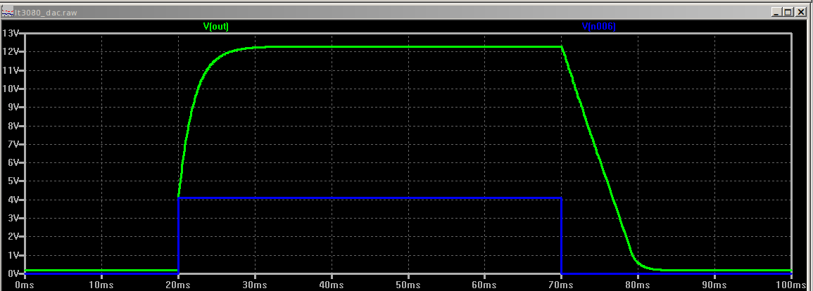
Then, there's stability. There's an interplay between C1 and C2. The LT3080 is stable with a minimum 2.2uF capacitor on the output; I've chosen 10uF here, although I may want to increase it after taking some noise measurements on the bench. Of course, driving a hefty capacitance like that with an op-amp is a recipe for instability unless the loop is properly compensated. With the AC feedback through 100nF at C2, the loop is safely over-compensated, as shown in this simulation of a full-swing 0-12.288V pulse:

For a power supply, this response is more than fast enough. With a larger output capacitor at C1 (or one in a circuit driven by the supply), C2 will need to be increased, slowing the response. The negative-edge slew rate of the output is limited by the sink current and C1, so an additional current sink (Q3) is added to speed the negative edge. Q1/Q2 are best used for low currents to avoid thermal issues between the mirror sides, while Q3 lacks the compliance range to provide the minimum load at low outputs. Together, these current sinks yield a well-behaved output over the full-voltage range. D1 supplies the reference voltage for the Q3 sink and functions as a power-on indicator (the specific LED at D1 was chosen from those available in the LTspice library; any green LED should work).
The output consists of separate force and sense lines for compensating voltage drop in the supply wires. In a lab supply, both lines would be brought out to the front panel so that they could be connected at the load point. R1 may provide enough ESD/overload protection for the op-amp, but a pair of diodes probably wouldn't hurt, assuming the leakage current was low enough.
 Ted Yapo
Discussions
Become a Hackaday.io Member
Create an account to leave a comment. Already have an account? Log In.
Yeah, I know exactly what your talking about when it comes to getting some of these LEDs, even the one's with good documentation I have found is still a question mark if you are not careful, like the ones I purchased (Prolight and Cree 1W and 3W LEDs,) although both preform pretty well within specs, the power supply is critical and needs to be regulated, because of temp and current can make them fluctuate outside of specs.
Are you sure? yes | no
What are the specs for the LEDs that you are using?
Are you sure? yes | no
In the general case, there aren't any specs - which is why I'm building the analyzer in the first place. Some LEDs come from ebay or aliexpress with minimal documentation, some are scavenged from old equipment or bought from surplus houses, and other just come with lousy documentation.
Are you sure? yes | no
But, here's an example of a decently documented LED.
http://www.lumileds.com/uploads/415/DS105-pdf
Even with this well-documented one, I had to measure it to get the relative efficiency curve.
Are you sure? yes | no
Hey Ted Yapo, well now, this is very interesting project you have here! Easy enough to test the diodes with a spectrometer, using a beam splitter and collimator. I am working on the project I have on hold right now, the one using the ELP cmos camera (machine vision,60/120fps) this spectrometer is going to be set up using fiber optics this time, with collimation entering the slit via fiber optic cabling.
Are you sure? yes | no
Yep, spectrometer measurements would be very interesting to add at some point. InGaN LEDs have a wavelength shift (aka "blue shift") with increasing current which isn't always well documented even when you can get a datasheet.
Are you sure? yes | no