Ted Yapo
-
Cheap Laser Diode Module Teardown
08/08/2016 at 17:35 • 0 commentsI found some red laser diode modules on ebay for the prototype. They were $0.285 each (qty. 100), which sounded really cheap - let's find out why. EDIT - I bought these in 2013; you can currently find them for $0.19 each on ebay with free shipping.
Here's the lot of them and an individual unit (6mm barrel diameter):
![]()
After destructively testing one of them electrically (details to come in the next log), I pulled it open:
![]()
The brass barrel contains a lens press-fit or secured with adhesive (I didn't take it out). Stuffed into a slot in the barrel is a sandwich of two fiberglass PCBs around a brass sheet with the diode die bonded to the top. When the diode was still intact, you could see the tiny gold bond wire attached to the top of the die. It remained with the positive PCB after disassembly:
![]()
I was actually quite surprised to find there was no encapsulation whatsoever; you could reach in (with a toothpick) and touch the die and bond wire. The board connected to the negative lead contains a series resistor measuring 33.2 ohms; this is intended to let you run the laser from a 3V DC supply - another surprise: no photodiode feedback, and no constant current driver. When I first played with laser diodes (780nm IR) in the late 1980s, they were finicky things, requiring special optical-feedback driver circuits for protection from over-current. Either they've improved substantially since then, or these diodes are destined for an early grave.
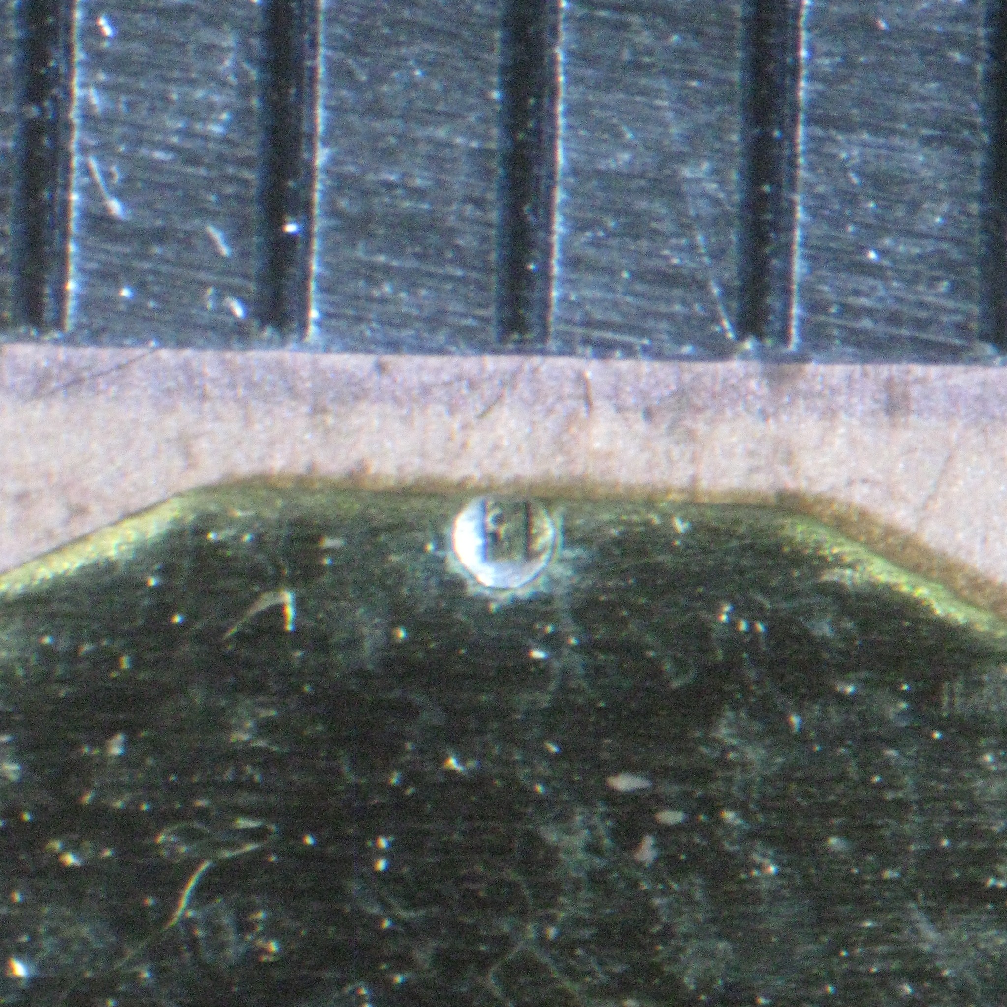
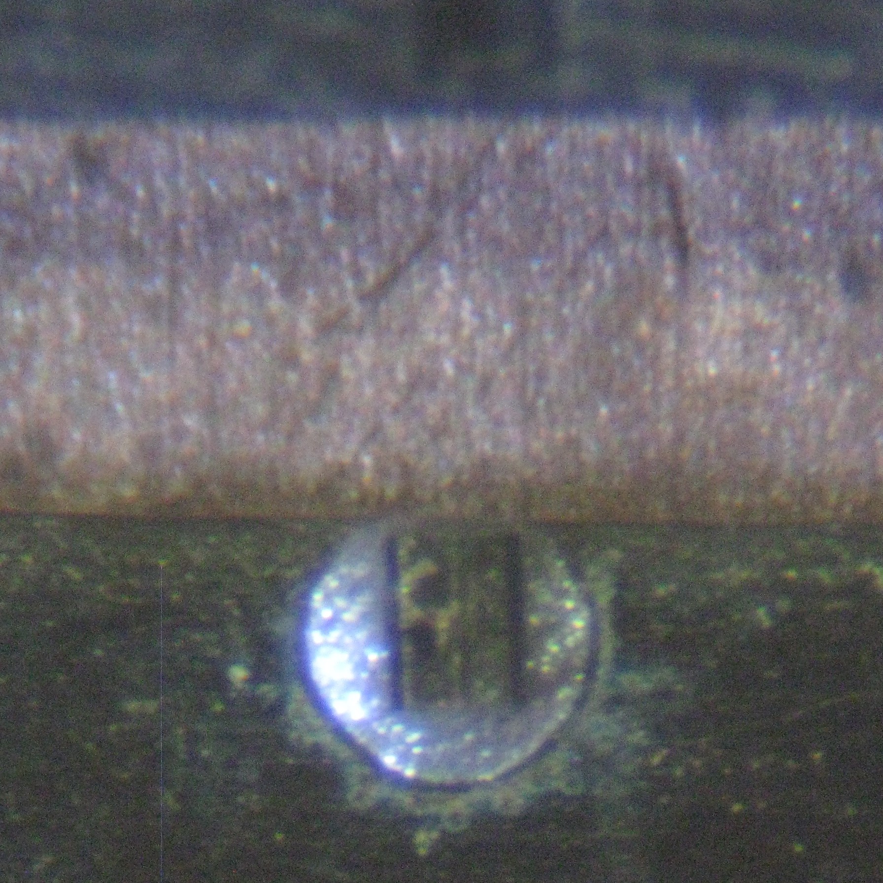
Here are some zooms of the die on the brass shim. It's probably bonded with conductive adhesive similar to that used to bond LEDs (see the Sparkfun Tutorial about how LEDs are made).
![]()
![]()
![]()
I've measured the I/V curve and optical output for one of these modules, and am working on a simple, fast, driver design. I'll present both next time.
-
Slow-Scan Prototype
08/04/2016 at 02:37 • 0 comments![]()
I think one of the reasons this project originally stalled was the daunting prospect of the mechanical design. Synchronizing code with precisely aligned mirrors spinning at high speeds doesn't sound easy. Of course, the way to attack such a problem is to break it into pieces, which is what I've been doing recently. I've decided for the first prototype to slow everything way down - below the flicker fusion rate - into the seconds-per-refresh region. Of course, the eye will no longer perceive the rendered image, but it can be captured in a long camera exposure. I've routinely done exposures of tens of minutes with a DLSR for astrophotography (too much stray light around here for much more), so a few seconds will be easy. The system won't be usable for a display, but I'll learn a lot about what it will take to make a real one, and prove (beyond simulation) that image formation is possible in this way.
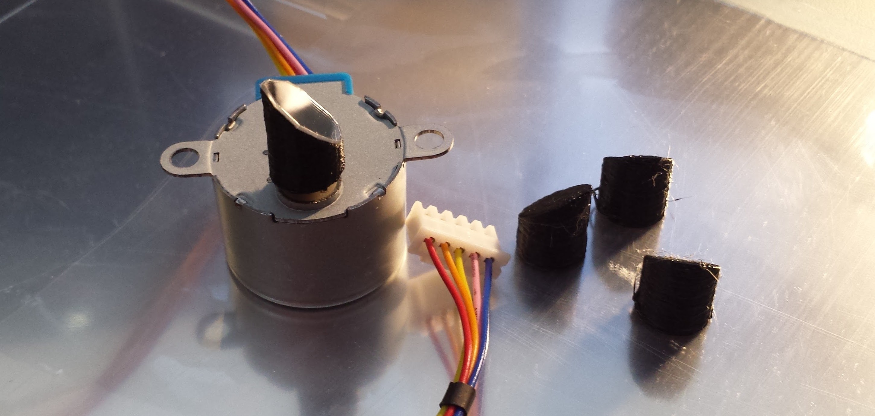
While high-speed motors would be required for a "live" system, a slow-scan approach allows the use of cheap stepper motors to drive the mirrors. I made a low-ball offer on (40) 28BYJ-48 geared stepper motors on ebay, and it got accepted, so I'm going to go with those. I have a few of them from other projects, and I know they have their issues, especially backlash in the gear train. Of course, I'm only going to drive them in one direction at a constant speed, so I don't expect too much trouble.
I designed a simple mirror mount in OpenSCAD and printed a few that fit tightly on the motor shaft (pictured above). I was lucky enough to find some thin polycarbonate mirrored sheets on Amazon. They're self-adhesive, but it doesn't stick particularly well, and probably won't work for the real system, but it seems good enough for a slow-scan prototype. The quality of the reflection is surprisingly good - once attached, the mirror isn't exactly flat, so it distorts a laser pointer beam a little, but it's probably good enough. I cut the first rough elliptical mirror with scissors, but I may end up just making round ones with a chassis punch.
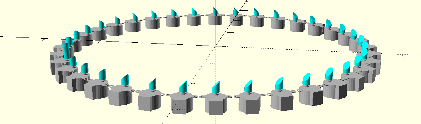
I decided to go with 36 lasers in the first prototype. Here's an early sketch of the possible layout - it's 500mm in diameter. The large size of the motors makes the ring larger than I really want, but I'm going to accept it. So far, I'm thinking of cutting a frame from medium-density fiberboard.
![]()
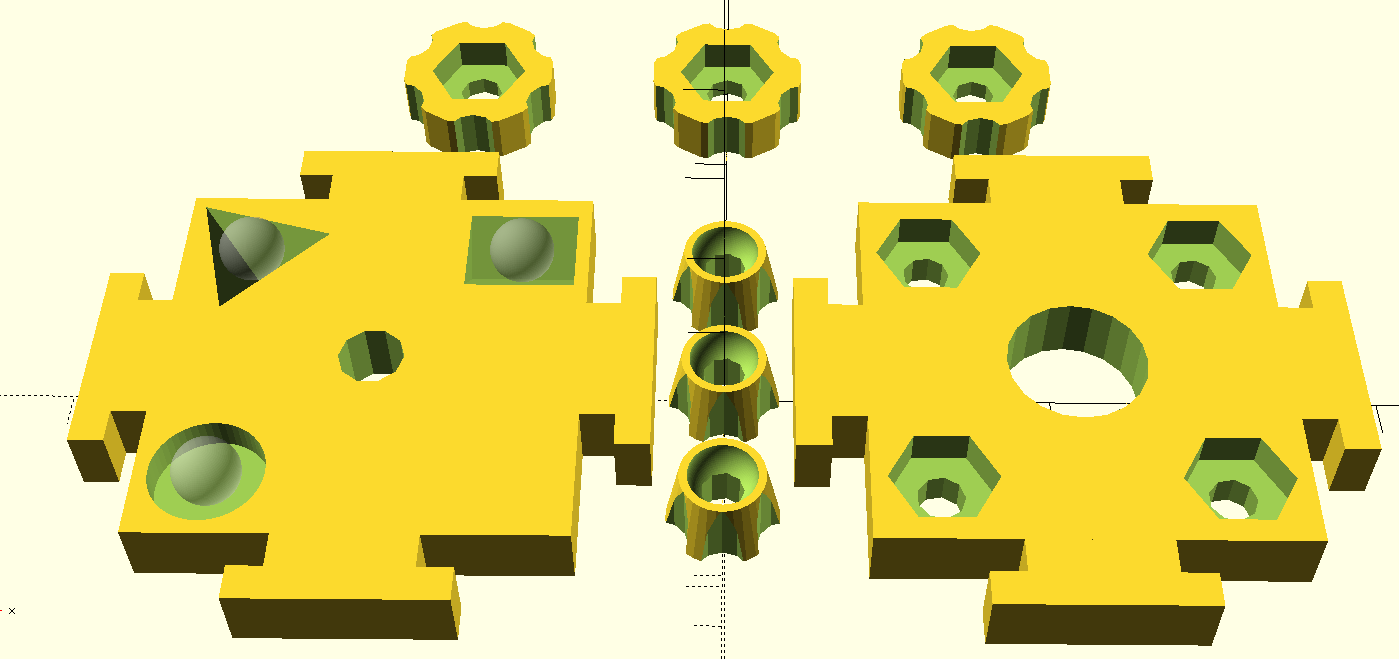
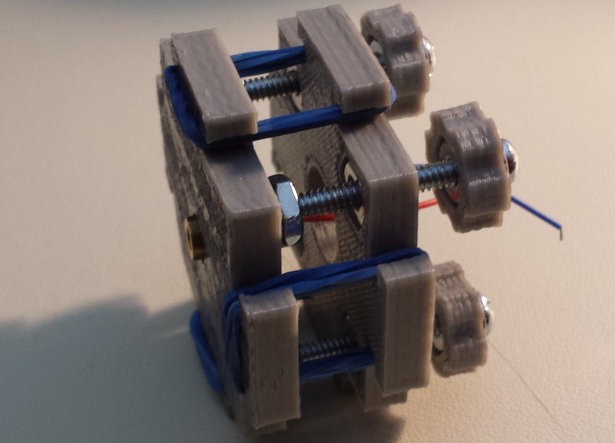
The last piece of the scanning mechanics is the laser mount. I'm still not sure if a simple 3D-printed interference-fit mount for the LD module will work, or if I will need to provide adjustments for aligning the laser. I have a design for a 3D-printed kinematic mount I made a while back that might be useful. It uses acorn (cap) nuts on 3D printed bearing surfaces.
![]()
In its current form, it's a bit large to incorporate into the display design, but I've printed a few of them, and they make decent precision alignment stages for laser diode modules:
![]()
I looked into using steel or glass inserts for the bearing surfaces, but I couldn't find anything suitable (and cheap). Acorn nuts on ABS or PLA seems to work OK, at least for light-duty use.
Mid-air Laser Image Display
A screen-free mid-air image display using a ring of lasers and rotating mirrors