Got back from holiday, so I have some time for this project again.
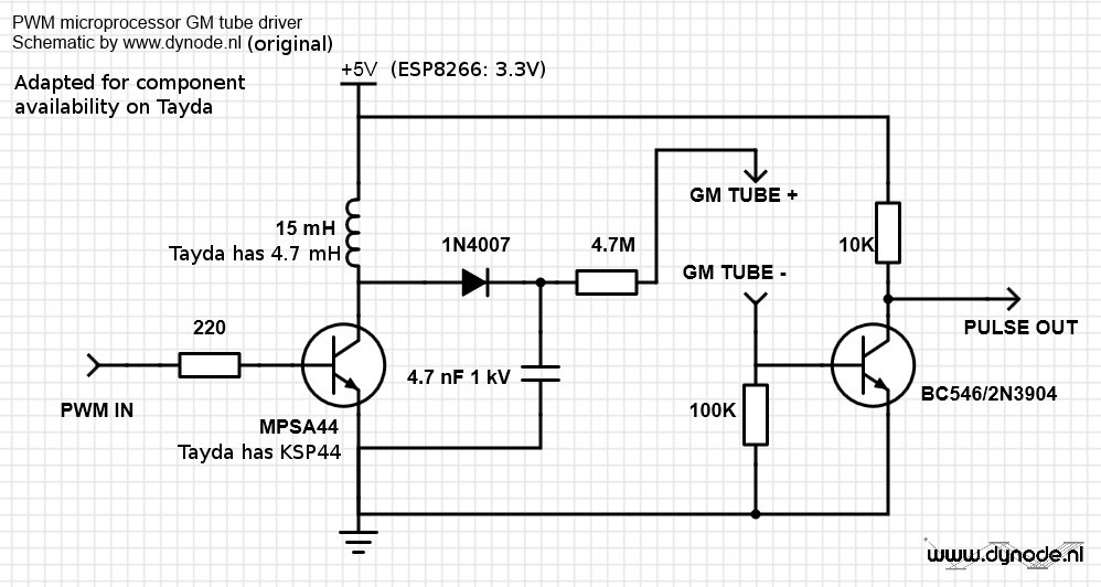
First is the schematic, which is taken almost unchanged from Johan at dynode.nl. He's using a trinket as brains for the whole thing, and thus has 5v input. The ESP8266 operates at 3.3V, so that's what I'll be feeding the circuit.
The inductor, diode and capacitor are forming a boost converter, that will be driven by the KSP44 which is turned on and off by a 10kHz PWM from the ESP8266. A full explanation of the circuit is given here.
I mentioned earlier that I want to keep the price as low as possible, and try to source all components from Tayda. The largest inductor they had was 4.7 mH, so that will have to do. And instead of the MPSA44 transistor they offer the KSP44.
Next log entry will be the simulation of the HV part in LTspice. I've already finished this, so expect this soon.
 biemster
Discussions
Become a Hackaday.io Member
Create an account to leave a comment. Already have an account? Log In.