Yaroslav Zhilin
-
Current Status, Future, and Revision 2
09/20/2016 at 14:44 • 0 commentsThis project was kind of on hold for the moment, but with all the sudden love from the community i think it deserves an update.
I have not yet figured out power. I might devise a way to sip power from the 120v Main, so I dont have to have an extra power supply. Thinking i'll just use a 5v power supply, since it will be pretty easy to make that work.
REVISION 2
Revision 2 of Arduino Watts is a thought now. Revision 2 will be a very similar concept and design, but with a more logical layout and design of circuitry. I wasn't extremely happy with the final layout, it became messy quickly once i had to keep adding wires into there. I was still figuring out the LCD and Arduino mini interconnects at the time of the design. I will be uploading the wiring diagram for that here shortly, keep an eye out for that.I got a new motherboard for my computer, a pretty snazzy one at that. It has a built-in bluetooth antenna, so i'm thinking i may try to include bluetooth in this revision, or the next one for sure. Obviously i'd get it working with USB first, as a proof of concept. Then i'll implement bluetooth so i dont have *more* wires running around my pc area.
More updates to come!
-
Powering the Arduino...
07/31/2016 at 18:01 • 3 commentsOne thing I have not decided on is powering the arduino. I have not gotten so far as to decide on or even figure out how to power it. A couple options would be to power it from the wall, by using a power 5v power supply and sticking it in a project box. Another option is some kind of battery, which woudlnt' make a whole lot of sense. The Third option is power it from USB and plug it into my computer. The only problem i have with that is it becomes dependant on having a USB power supply. I think I may opt for the power supply option, as i could fit one either in the project box or the outlet-in-a-box i have. Decisions, decisions!
-
Day 1-5
07/31/2016 at 17:56 • 0 commentsLate to the project logs, so this has to be a combine effort!
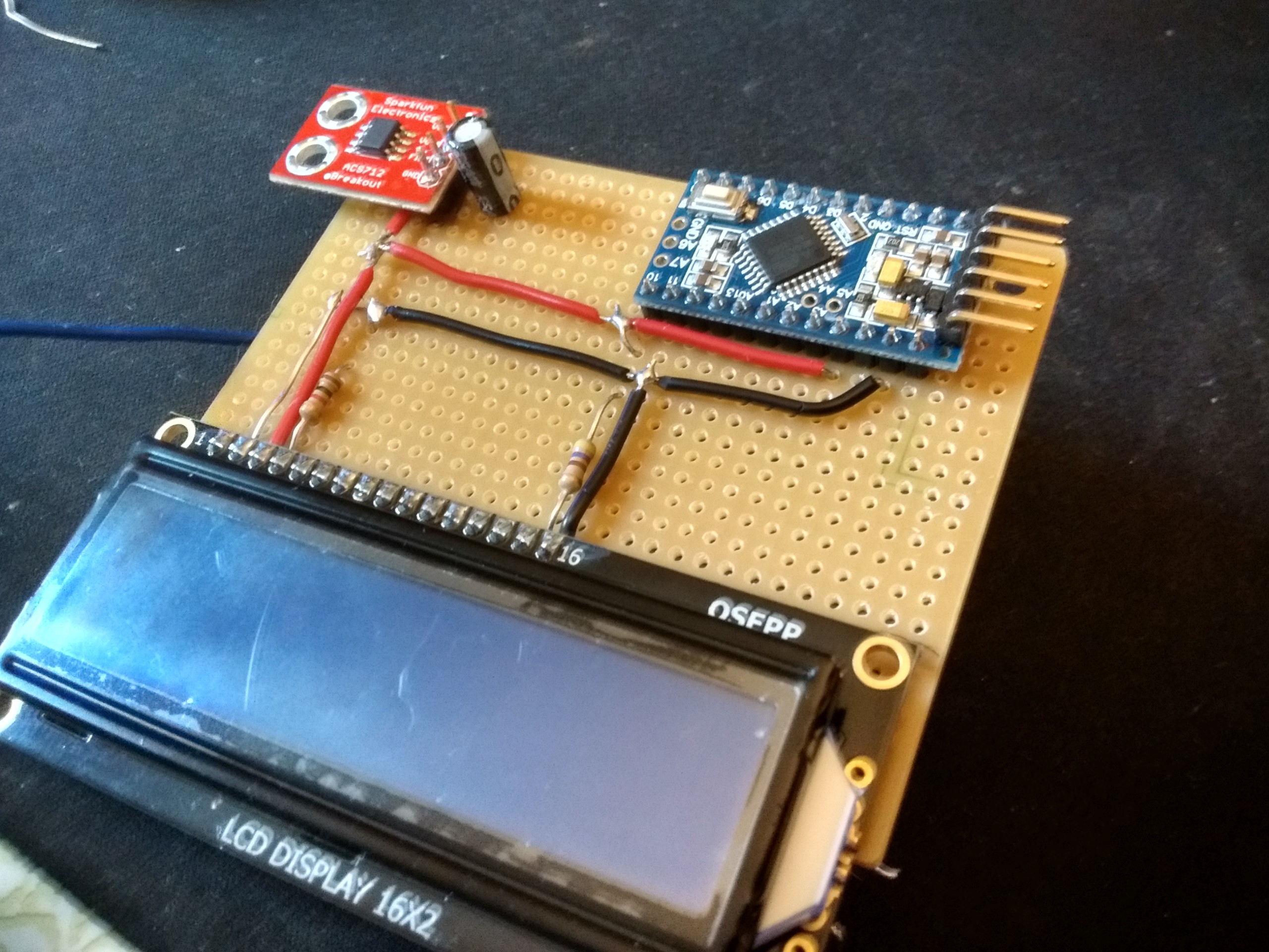
Starting placing and soldering components on the board.
![]()
The general concept is Power is run on the surface, and data is run on the underside. Why i chose this is simply looks. The clean power runs look a lot nicer than the spaghetti mess that will become the underside. The only exception to this is for the ACS712 sensor; I had to solder on header pins through the breadboard, so i decided to run the power under the board for that. The header pins also raise the breakout board slightly, allowing me to run the 5v right under it. This works out for me since the 5v pin is the top most header. The resistors are there for contrast and brightness of the LCD and are the combination i think looks the best. I believe that they are 1k and 470.
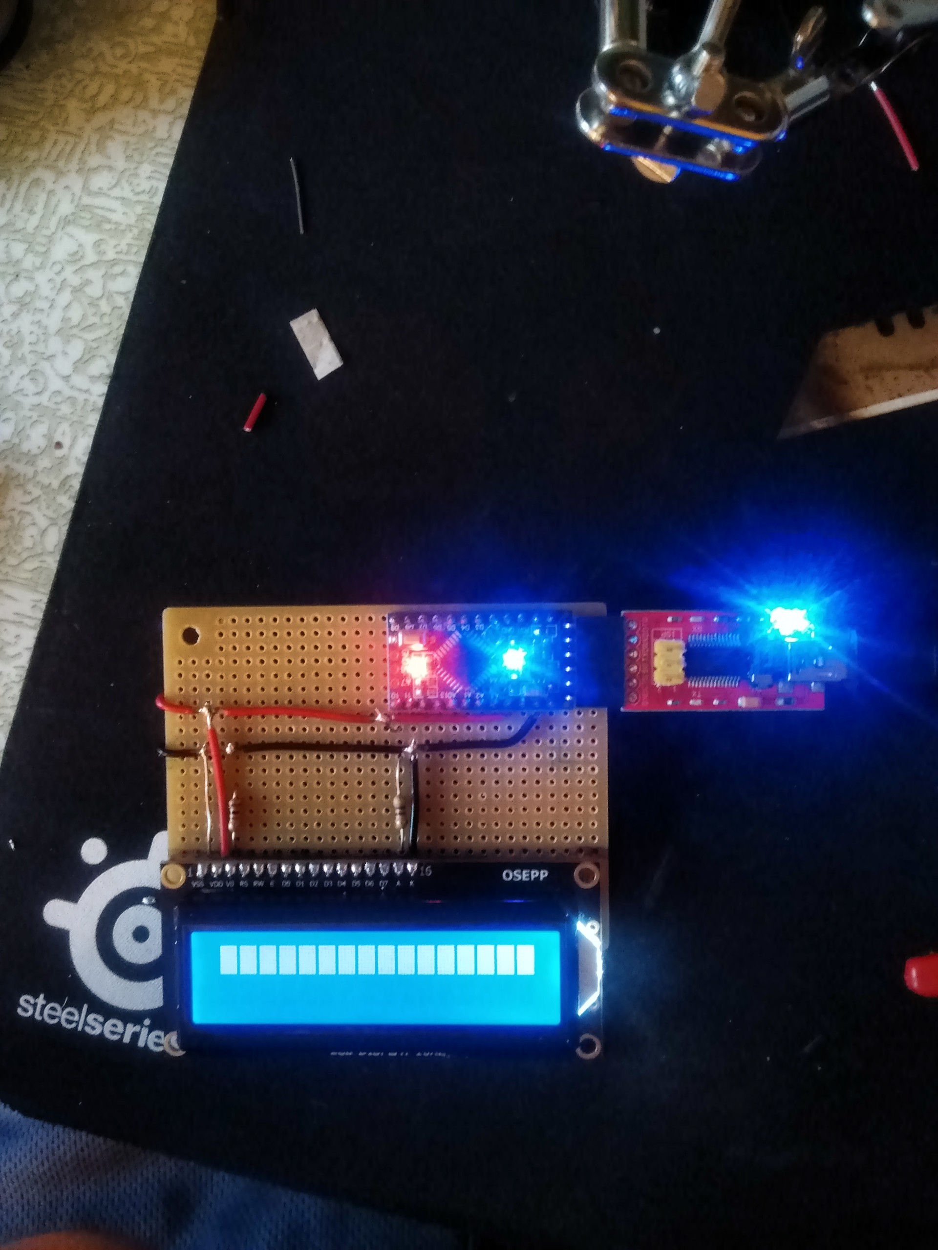
Initial testing after wiring in power only, before i put on(or even owned) the ACS712:
![]()
Nothing too exciting there. I havent' even trimmed off excess wire at this stage yet.